| (19) |
 |
|
(11) |
EP 0 394 426 B1 |
| (12) |
EUROPEAN PATENT SPECIFICATION |
| (45) |
Mention of the grant of the patent: |
|
17.01.1996 Bulletin 1996/03 |
| (22) |
Date of filing: 22.08.1989 |
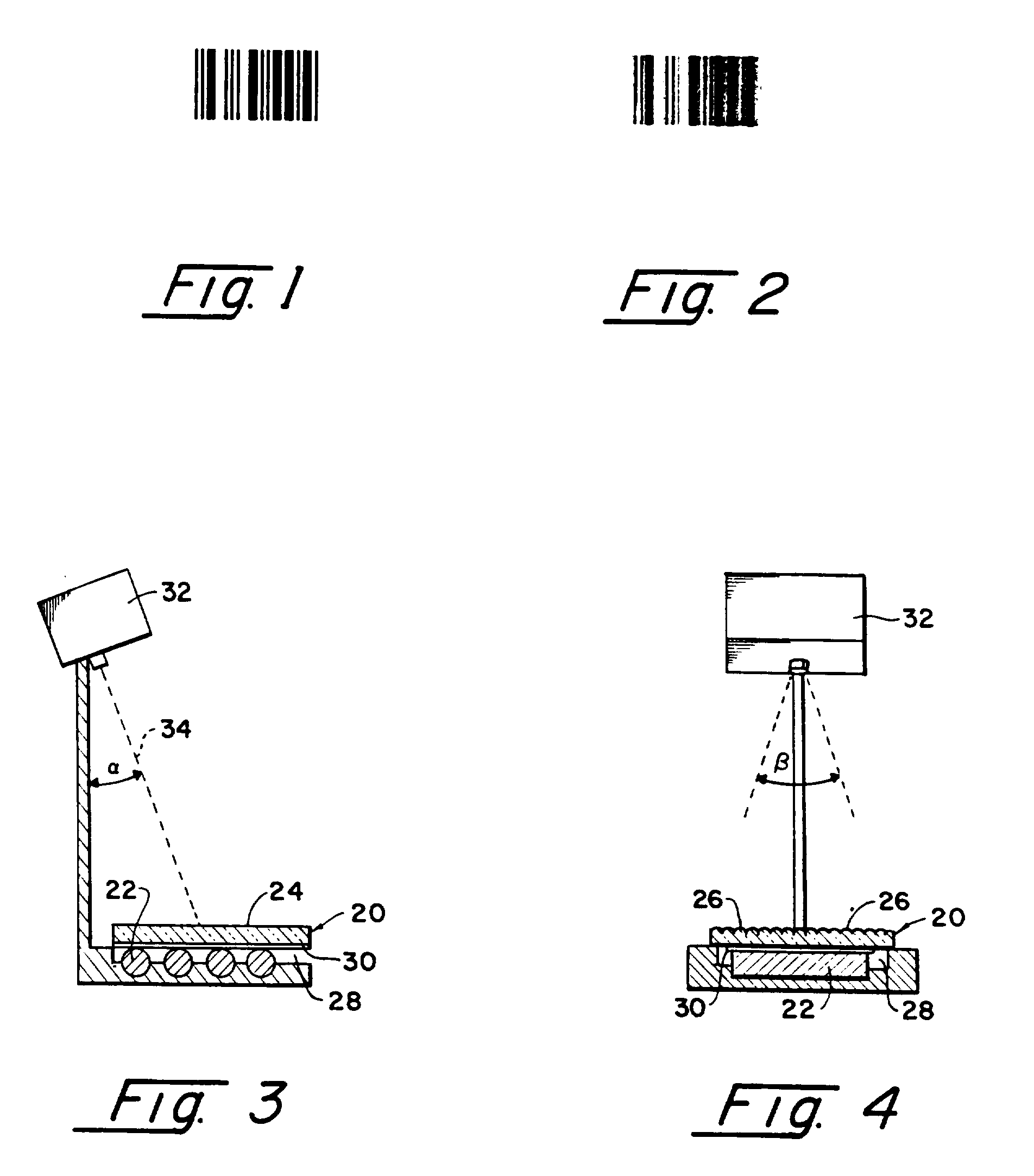
|
| (51) |
International Patent Classification (IPC)6: G09C 5/00 |
| (86) |
International application number: |
|
PCT/US8903/617 |
| (87) |
International publication number: |
|
WO 9004/245 (19.04.1990 Gazette 1990/09) |
|
| (54) |
METHOD AND APPARATUS FOR SCRAMBLING AND UNSCRAMBLING BAR CODE SYMBOLS
VERFAHREN UND VORRICHTUNG ZUM VERSCHLÜSSELN UND ENTSCHLÜSSELN VON BALKENCODE-SYMBOLEN
PROCEDE ET APPAREIL DE BROUILLAGE ET DE DEBROUILLAGE DE SYMBOLES DE CODES A BARRES
|
| (84) |
Designated Contracting States: |
|
DE FR GB IT NL |
| (30) |
Priority: |
06.10.1988 US 254388
|
| (43) |
Date of publication of application: |
|
31.10.1990 Bulletin 1990/44 |
| (73) |
Proprietor: ALASIA, Alfred V |
|
Whitestone, NY 11357 (US) |
|
| (72) |
Inventor: |
|
- ALASIA, Alfred V
Whitestone, NY 11357 (US)
|
| (74) |
Representative: Kerr, Simonne June et al |
|
European Patent Attorney
POTTS, KERR & CO.
P.O. Box 688
Ascot
Berkshire SL5 8YT
Ascot
Berkshire SL5 8YT (GB) |
| (56) |
References cited: :
EP-A- 0 194 115
US-A- 3 781 109
US-A- 4 198 147
US-A- 4 420 221
|
US-A- 3 225 457
US-A- 4 023 902
US-A- 4 202 626
|
|
| |
|
|
|
|
| |
|
| Note: Within nine months from the publication of the mention of the grant of the European
patent, any person may give notice to the European Patent Office of opposition to
the European patent
granted. Notice of opposition shall be filed in a written reasoned statement. It shall
not be deemed to
have been filed until the opposition fee has been paid. (Art. 99(1) European Patent
Convention).
|
[0001] The present invention relates to systems for scrambling and unscrambling bar codes,
and more particularly to apparatus for and method of minimizing the counterfeiting
of and for verifying the authenticity of a bar code.
[0002] When there is a need to track, identify and enter information about persons, places
and things into computer-based systems, bar coding currently provides one of the most
accurate, efficient and cost-effective systems compared with other data entry systems.
Bar coding is generally regarded as the industry standard for automated data collection;
other machine-reading techniques, such as optical character recognition, magnetic
stripes and punch cards have now fallen behind in general usage for a number of reasons.
For example, magnetic stripes are relatively expensively printed or applied by hot
stamping, but cannot be read at a distance, and often are subject to easy alteration
of the recorded data, hence are at a distinct disadvantage where data security is
important. Optical character recognition is not as accurate, flexible and reliable
as bar code symbol scanning because it usually contains no vertical redundancy or
internal checking. Punch card entry is too slow for current computer speeds and exhibits
an operator keyboard entry error ratio of about 1:300, whereas the much faster optical
character recognition provides an error ratio of about 1:10,000, and reading bar codes
symbols has an error ratio of about 1:3,000,000.
[0003] A bar code symbol, for purposes of the present exposition, can be defined as a graphically
reproduced array of elements formed as various width, parallel, rectangular bars,
and the spaces between such bars, representing one or more characters in a numerical
or alphanumerical set. The symbol is generally printed in a single color on an optically
color-contrasting background, and by convention, the bars in the set are considered
to be the darker of the contrasting elements. The number of elements in each character
can range widely, e.g. typically from 7 to 16 depending upon the particular bar code
selected. A bar code symbol generally contains a leading quiet zone, a start character,
one or more data characters including often a check character, a stop character and
a trailing quiet zone. The term "module", as applied to bar code symbols, is understood
to refer to the narrowest nominal bar or space in the code, wider bars and spaces
usually being specified as multiples of a module. The spatial frequency of the modules
is thus defined in terms of the number of modules per unit distance (e.g. an inch
or centimeter) in the printed symbol.
[0004] Bar codes are generally read by optically scanning a light beam transversely across
all of the elements of the symbol. The term "light" as used herein is to be interpreted
as including a wider band of radiation than the visible spectrum, and is deemed to
include ultra violet and infra-red radiation as well. The reflections of the scanning
light from the symbol or emissions excited by the scanning light are converted to
electrical signals. Because the information in the symbol is carried by the relative
widths of the bars and spaces in each character, the electrical signals are then usually
decoded by an electronic computer or decoder to recover that information, typically
in a form comprehensible usually to the computer.
[0005] A large number of such bar codes has been developed since their original introduction
sometime during the 1960s. Current examples of such developments are the well-known
and widely used Two of Five Code, UPC and Codabar, all of which have 12 or less principal
characters and are thus primarily numerical codes, Code 39 that is an alphanumeric
bar code including 44 characters, and many others.
[0006] Usually, the smallest average module in a bar code symbol ranges in width between
0.017 and 0.026 cms (0.0065 and 0.0104 inches). Bar codes symbols with modules of
these substantial dimensions can thus be successfully printed by almost any printing
process in general usage, hence have previously been readily duplicated even xerographically
or counterfeited by other printing processes. Because bar code symbols have now found
widespread usage to provide machine-readable indicia on tags and labels attached to
merchandise such as groceries, clothing and the like, and printed on machine-read
documents such as transit passes and the like, counterfeiting of the bar code symbol
has become a serious problem. Counterfeiting of documents costs the American public
billions of dollars annually, and is responsible for the loss of hundreds of thousands
of jobs. Worldwide trade suffers seriously from well-organized and extensive counterfeiting
piracy of products such as watches, luggage, clothing and the like, financial instruments
such as certificates of deposit, lottery tickets, tax stamps, bank checks, stock certificates
and the like, and other important documents such as identification cards, passports
and the like.
[0007] US-A. 3,937,565; 3,769,890; 4,092,654; and 4,198,147 disclose anticounterfeiting
systems that involve forming a parallax panoramagram image, typically photographically
through a lenticular line screen (i.e. a lineticular screen), usually having a spatial
line frequency of 27.16/cm (69/inch). The resulting image is a scrambled lineticular
dissection of a subject, which image is difficult or even impossible to read visually
and resists ready reproduction by photographic or xerographic techniques, the extent
of scrambling provided by this system being controlled by a large variety of parameters
peculiarly under the control of the originator of the scrambled image. The scrambled
image can be unscrambled to be examined as by visual reading, by a simple decoder
that in effect is a duplicate of the lenticular screen used to form the original image.
Such scrambled images have found widespread usage in security printing of bank notes,
stock certificates, bonds, travelers checks, lottery tickets, passports, airline tickets,
gift certificates, bank checks, postal money orders and similar instruments, all with
a remarkable record of substantially no losses or fraud due to counterfeiting.
[0008] The scrambling process of the aforementioned patents with the standard lenticular
line screen of 27.16/cm (69 lines/inch) does not, however, offer substantial anticounterfeiting
protection to standard bar code symbols because the latter, being an array of a series
of parallel bars that necessarily are highly contrasted with their background, when
scrambled in this manner do not readily resist either photographic or xerographic
duplication.
[0009] A principal object of the present invention is therefore to provide apparatus for
and method of unscrambling a scrambled parallax panoramagram of a bar code symbol,
which panoramagram is highly resistant to unauthorized duplication.
[0010] To effect the foregoing and other objects of the present invention, a parallax panoramagram
that is a lineticular dissection of a bar code symbol is formed by scrambling the
bar code in accordance with a graticule formed of a plurality of parallel contiguous
focussing elements, all as taught in the foregoing U.S. Patents 3,937,565; 3,769,890;
4,092,654; and 4,198,147, but here at a spatial frequency at or greater than the modular
frequency of the bar code, preferably at least about 61 elements per cm (155 elements
per inch) for those current bar code symbols that have the narrowest modules. Panoramagrams
thus produced are decoded by placing them in contiguous relation to a first surface
of a light transparent screen having a plurality of elongated parallel line elements
including focussing surfaces disposed in common along the opposite or second surface
of the screen, the screen and panoramagram being relatively positioned so that the
line elements of the screen are substantially parallel to the lines in the lineticular
dissection. The spatial frequency of the line elements of the screen is necessarily
matched to the spatial frequency of the focussing elements of the graticule.
[0011] The panoramagram is examined through the screen preferably by scanning the panoramagram
typically with a laser beam swept across the second surface of the screen transversely
to the axes of the screen's line elements, the beam having a cross-section dimension,
where incident on the screen, not greater than the width of one of the line elements.
Preferably, during scanning, the beam is directed toward the screen in a direction
substantially parallel to the axes of the line elements of the screen and at a non-perpendicular
angle below the critical angle to the mean plane of said screen, e.g. at about 20
degrees from a perpendicular to the plane of the screen. Light reflected from or excited
by the scan of said beam across the panoramagram is then converted into electrical
signals and represents an unscrambled version of the original bar code symbol.
[0012] Other objects of the present invention will in part appear obvious and will in part
appear hereinafter. The invention accordingly comprises the apparatus possessing the
construction, combination of elements and arrangement of parts, and the method comprising
the several steps, and the relation of one or more of such steps with respect to each
of the others, all of which are exemplified in the following detailed disclosure and
the scope of the application of which will be indicated in the claims.
[0013] For a fuller understanding of the nature and objects of the present invention, reference
should be had to the following detailed description taken in connection with the accompanying
drawing wherein:
Fig. 1 is an example of a typical original or unscrambled bar code symbol (Two of
Five);
Fig. 2 is a representation of a scrambled image of the bar code symbol of Fig. 1 provided
by the method of the present invention;
Fig. 3 is a side view, partly in cross-section of a simplified embodiment of a system
for unscrambling a scrambled image of a bar code symbol provided by the method of
the present invention; and
Fig. 4 is a front view, partly in cross-section of the system of Fig. 3.
[0014] As noted earlier herein, a scrambled image (Fig. 2) of a bar code symbol (Fig. 1)
is preferably produced by any of the techniques described in the aforesaid U.S. Patents
3,937,565; 3,769,890; 4,092,654; and 4,198,147, and need not be further described
herein except as follows: When bar code symbols are imaged in such prior art scrambling
systems using a graticule that is a lineticular screen having a spatial line frequency
(e.g. 27.16 lines/cm (69 lines/inch), the current standard) smaller than the nominal
spatial modular frequency of the bar code symbol, scrambling or encoding is very poorly
achieved, if at all. The resulting image can be readily read visually and can be easily
duplicated xerographically, thereby providing little or no security against unauthorized
copying. It has now been found that a well-scrambled, machine readable panoramagram,
highly resistant to being copied or duplicated as by xerographic reproduction, is
provided when the graticule used to effect the scrambling process is formed with a
line frequency greater than the spatial modular frequency of the bar code symbol and
the scrambling process is carried out with the lines or contiguous, focussing elements
of the graticule substantially parallel to the modules of the bar code symbol. Preferably,
because current bar code modules have widths generally above .017 cm (0.0065 inches)
in width (and thereby exhibit a spatial frequency of less than about 155 line/25.4
mm) it is preferred to use a graticule of at least that frequency, but preferably
greater (e.g. 177 elements/25.4 mm), to scramble and unscramble the resulting panoramagram.
It will, however, be appreciated that the number of contiguous focussing elements
per inch in the scrambling graticule and unscrambling screen can be at any other frequency
dependent upon the nominal modular width of the bar code to be used and the physical
restraints imposed by the requirement of manufacturing the graticule and printing
the bar code symbols from the resulting image. It has also been found that optimum
scrambling will occur when the modules of the bar code symbol being scrambled are
positioned, during the scrambling process, substantially parallel with the focussing
elements of the graticule.
[0015] The present invention particularly involves unscrambling the parallax panoramagram
of the bar code symbol, and to that end, as shown in Figs. 3 and 4 (wherein like numerals
denote like parts) the invention comprises light transparent screen 20 having a typically
flat or planar bottom surface 22 and upper surface 24 characterized in having disposed
in common thereon a plurality of line elements 26 defined by elongated, parallel focussing
surfaces. In a preferred embodiment, both the graticule used to scramble the bar code
symbol and screen 20 are substantially identical lineticular screens in which line
elements 26 are hemicylindrical, anamorphic lenses, the radius of curvature of each
of the hemicylindrical lens surfaces being about 7.62 cm (0.3 inches), and the thickness
of screen 20 between lower surface 22 and the common plane tangent to all of the lenses
forming line elements 26, being about 2.67 mm (0.105 inches).
[0016] Because the line frequency of screen 20 is identical to that of the graticule used
to scramble the bar code symbol to be unscrambled, and as noted the line frequency
of that graticule depends heavily upon the modular frequency of the symbols of the
bar code of interest, typically where the smallest width of a module of that bar code
is not less than about .15 mm. (0.006 inches) the spatial frequency of said screen
should be at least about 155 line elements per 25.4 mm. and preferably is a larger
value, for example 177 line elements per 25.4 mm.
[0017] It will be appreciated that the unscrambling process requires that the panoramagram
to be unscrambled be disposed contiguous to surface 22, so that the scrambled image
is in the same relation to the focussing surfaces of line screen 20 as they were to
the graticule. Similarly, it is important that line elements 26 and the lines in the
lineticular dissection to be unscrambled be positioned substantially parallel to one
another. To these ends, the embodiment of Figs. 3 and 4 includes decoding chamber
28 positioned immediately below surface 22 and into which can be inserted, with proper
orientation, a sheet bearing a parallax panoramagram of the type to be unscrambled,
so that such panoramagram can be examined through the screen. Means such as rollers
29 or the like, are shown for holding panoramagram 30 at least in contiguous relation
with surface 22.
[0018] In the present invention, unscrambling is achieved by examining the scrambled bar
code symbols in panoramagram 30 disposed in chamber 28. For example, ordinarily the
panoramagram will be rendered as a positive photographic silver image or printed in
ordinary ink on a highly contrasting background, and the scrambled image can be examined
by reflection of light therefrom. Alternatively, the panoramagram can be printed in
an ink substantially invisible under ordinary illumination by visible radiation, which
ink, however, can be rendered visible by absorption of, for example, ultraviolet radiation.
In the latter instance, of course, screen 20 is necessarily formed of a material transparent
and refractive to such excitation radiation. Where it is desirable to read the panoramagram
by machine, as in the present case, it is preferable not to depend upon ambient illumination,
but to provide a source of light that is more dependable and that can be, if desired,
carefully matched to a detector.
[0019] To those ends, the present invention thus includes means, such as scanning source
and detector 32, for producing a beam of light and for directing it through screen
20 wherein it either reflects from panoramagram 30 or excites emissions from the panoramagram.
Source 32 is typically a commercially available laser or solid state scanner such
as the Laserscan 6500 sold by Symbol Technologies Inc. of Bohemia, N.Y. or described
in U.S. Patents No. 4,387,297 and 4,409,470. Where source 32 includes a laser, typically
the latter generates a substantially coherent monochromatic beam, typically red light
with a center frequency of about 633 nanometers, that conveniently can have a very
small cross-section dimension. Alternatively, source 32 can produce a beam of ultraviolet
radiation (typically at wavelengths of 254 or 367 nanometers) for use where the panoramagram
is rendered, as by printing, in "invisible" ink that will fluoresce when excited by
ultraviolet radiation. In any case, source 32 functions to scan panoramagram 30 by
generating beam 34 and moving the beam across surface 24 of screen 20 transversely
to the parallel axes of elongation of line elements 26 at least through an angle B
subtending the full width of panoramagram 30. Importantly, it has been found that
beam 34 will not properly unscramble the panoramagram unless the cross-section dimension
of the beam, where incident on surface 24, is not greater than the width of line element
or hemicylindrical lens 26.
[0020] Where typically screen 20 is a substantially planar screen, source 32 should be so
positioned with respect to screen 20 that beam 34 is directed toward the screen substantially
parallel to the axes of elongation of elements 26 and at a non-perpendicular angle
below the critical angle to the mean plane of the screen. The angle of incidence of
beam 34 on screen 20 is fairly critical in that substantial deviation from a preferred
angle will result in inferior performance or in no unscrambling at all. Thus, for
the Laserscan 6500 scanner, angle preferably is about 20 degrees from a perpendicular
to the plane of screen 20.
[0021] As is well known in the art, commercially available scanners such as described detect
light reflected from or excited by the scan of beam 34, and convert the now unscrambled
bar code symbol represented by the detected light into electrical signals. Those electrical
signals can then be transmitted to a decoding system, such as a digital computer and
decoded in a manner known to those skilled in the bar code art, to represent the number
or alphabetical indicia represented by the bar code symbol.
1. A method of coding and decoding a bar code, which includes the steps of forming a
parallax panoramagram (30) that is a lineticular dissection of an image formed by
scrambling the image in accordance with a graticule formed of a plurality of parallel
contiguous focussing elements, providing a light transparent screen (20) having a
plurality of elongated parallel line elements (26) including focussing surfaces disposed
in common along a first surface of the screen, the spatial frequency of the line elements
(26) of the screen (20) being matched to the spatial frequency of the focussing elements
of the graticule, positioning the panoramagram (30) contiguous to the opposite surface
of the screen with the line elements disposed substantially parallel to the lines
in the lineticular dissection and examining the panoramagram (30) through the screen
(20), the method being characterized in that the image is a bar code and the focussing
elements of the graticule have a spatial frequency greater than the modular spatial
frequency of the bar code.
2. A method according to claim 1, characterized in that the step of examining comprises
producing a beam of light; scanning the panoramagram by moving the beam across the
first surface of the screen transversely to the line axes of the line elements, the
beam being produced with a cross-section dimension, where incident on the screen,
not greater than the width of a line element; and detecting light emitted from a registered
panoramagram and screen as the result of the scan of the beam across a registered
panoramagram and screen, and converting the emitted light into electrical signals
representing an unscrambled version of the bar code.
3. A method according to claim 1, characterized in that it includes the step of positioning
the modules of the bar code substantially parallel to the focussing elements of the
graticule when forming the panoramagram.
4. A method according to claim 1, characterized in that both the graticule and the screen
have the same predetermined thickness and predetermined curvature of the focussing
elements and focussing surfaces.
5. A method according to claim 1, characterized in that the graticule has at least about
155 elongated focussing elements to 25.4 mm.
6. Method of unscrambling a parallax panoramagram (30) that is a lineticular dissection
of an image, formed by scrambling the image in accordance with a graticule having
a plurality of parallel contiguous focussing elements, comprising the steps of providing
a light transparent screen (20) having a plurality of elongated parallel line elements
(26)including focussing surfaces disposed in common along a first surface of the screen,
the spatial frequency of the line elements (26) of the screen being matched to the
spatial frequency of the focussing elements of the graticule; positioning the panoramagram
(30) contiguous to the opposite surface of the screen with the line elements disposed
substantially parallel to the lines in the lineticular dissection; the method being
characterized in that the image is a bar code and the focussing elements of the graticule
are disposed at a spatial frequency greater than the modular spatial frequency of
the bar code, the method also including the further steps of examining the panoramagram
through the screen by producing a beam of light; moving the beam across the first
surface of the screen transversely to the axes of the line elements so as to scan
the panoramagram, the beam being produced with a cross-section dimension, where incident
on the screen, not greater than the width of a line element (26); detecting light
emitted from a registered panoramagram and screen as the result of the scan of the
beam across the registered panoramagram and screen, and converting the emitted light
into electrical signals representing an unscrambled version of the bar code.
7. A method according to claim 6, characterized in that the screen is provided as a substantially
planar screen and wherein the beam during scanning is directed toward the screen substantially
parallel to the axes and at a non-perpendicular angle below the critical angle to
the mean plane of the screen.
8. A method according to claim 6, characterized in that the screen is substantially planar
and the beam, during scanning, is directed toward the screen substantially parallel
to the axes and at about 20 degrees from the perpendicular.
9. A method according to claim 6, characterized in that the beam is produced as a substantially
coherent monochromatic beam.
10. A method according to claim 9, characterized in that the beam is produced as red light
at a center wavelength of about 633 nanometers.
11. A method according to claim 6, characterized in that the panoramagram is formed in
a material that will fluoresce when excited by ultraviolet radiation and wherein the
beam is produced as ultraviolet light.
12. An apparatus for unscrambling a scrambled parallax panoramagram (30) formed by scrambling
an image in accordance with a graticule having a plurality of parallel, contiguous,
focussing elements, the apparatus having a light transparent screen (20) having a
plurality of elongated parallel line elements (26) having focussing surfaces disposed
in common along one surface (24) of the screen, optical scanning means (32) for producing
a beam of light (34) and being disposed with respect to the screen for scanning the
beam across the first surface of the screen transversely to the line axes of the line
elements and means (28) for positioning the panoramagram contiguous to the opposite
surface of the screen with the line elements disposed substantially parallel to the
lines in the lineticular dissection, characterized in that the panoramagram is a lineticular
dissection of a bar code formed with a graticule wherein the focussing elements of
the graticule are disposed at a spatial frequency greater than the modular spatial
frequency of the bar code, the spatial frequency of the line elements of the screen
are matched to the spatial frequency of the focussing elements and the beam, where
incident on the screen, has a cross-section dimension not greater than the width of
a line element.
13. An apparatus according to claim 12, characterized in that the screen is a lineticular
screen and the line elements are hemicylindrical lenses.
14. An apparatus according to claim 13, characterized in that the radius of curvature
of each of the hemicylindrical lens surfaces is about 7.62 mm (0.3 inches).
15. An apparatus according to claim 13, characterized in that the thickness of the screen
is about 2.67 mm (0.105 inches).
16. An apparatus according to claim 12, characterized in that the smallest width of a
module of the bar code is not less than about .15 mm (0.006 inches) and the spatial
frequency of the screen is at least about 155 line elements per 25.4 mm.
17. An apparatus according to claim 12, characterized in that the smallest width of a
module of the bar code is not less than about .15 mm (0.006 inches) and the spatial
frequency of the screen is about 177 line elements per 25.4 mm.
18. An apparatus according to claim 12, characterized in that the graticule has a predetermined
thickness and a predetermined curvature of surfaces of the lens elements and the line
elements in the screen have the same thickness and radius of curvature as the focussing
elements in the graticule.
19. An apparatus according to claim 12, characterized in that the screen has the same
configuration as the graticule.
20. An apparatus according to claim 19, characterized in that the screen is substantially
planar.
21. An apparatus according to claim 12, characterized in that it includes means for detecting
light reflected from the scan of the beam across a registered panoramagram and screen
and for converting the reflected light into electrical signals representing an unscrambled
version of the bar code.
22. An apparatus according to claim 21, characterized in that the optical scanning means
includes a laser.
23. An apparatus according to claim 22, characterized in that the laser generates red
light at a center wavelength of about 633 nanometers.
24. An apparatus according to claim 21, characterized in that the optical scanning means
comprises a solid state light source.
25. An apparatus according to claim 24, characterized in that the optical scanning means
comprises a source of ultraviolet light.
26. An apparatus according to claim 21, characterized in that the screen is substantially
planar and the beam is directed toward the screen at a non-perpendicular angle below
the critical angle to the mean plane of the first surface.
27. An apparatus according to claim 21, characterized in that the screen is substantially
planar and the beam is directed toward the screen parallel to the line elements and
at about 20 degrees from the perpendicular.
1. Verfahren zur Codierung und Decodierung eines Balkencodes, das die Schritte umfaßt,
daß ein Parallaxenpanoramagramm (30) gebildet wird, das eine Lineticularzerlegung
eines Bildes ist, das durch Verwürfeln des Bildes gemäß einem aus einer Anzahl von
parallelen benachbarten Fokussierelementen gebildeten Raster gebildet ist, eine lichtdurchlässige
Rasterscheibe (20) mit einer Anzahl von langgestreckten parallelen Linienelementen
(26) vorgesehen wird, aufweisend gemeinsam entlang einer ersten Fläche der Rasterscheibe
vorgesehene Fokussierflächen, wobei die Ortsfrequenz der Linienelemente (26) der Rasterscheibe
(20) an die Ortsfrequenz der Fokussierelemente des Rasters angepaßt ist, das Panoramagramm
(30) benachbart der gegenüberliegenden Fläche der Rasterscheibe positioniert wird,
wobei die Linienelemente im wesentlichen parallel zu den Linien in der Lineticularzerlegung
angeordnet sind, und das Panoramagramm (30) durch die Rasterscheibe (20) untersucht
wird, wobei das Verfahren dadurch gekennzeichnet ist, daß das Bild ein Balkencode ist und die Fokussierelemente des Rasters eine Ortsfrequenz
größer als die modulare Ortsfrequenz des Balkencodes aufweisen.
2. Verfahren nach Anspruch 1, dadurch gekennzeichnet, daß der Untersuchungsschritt umfaßt, daß ein Lichtstrahl erzeugt wird, das Panoramagramm
abgetastet wird, indem der Strahl über die erste Fläche der Rasterscheibe quer zu
den Linienachsen der Linienelemente bewegt wird, wobei der Strahl mit einer Querschnittabmessung,
wo auf die Rasterscheibe auffallend, nicht größer als die Breite eines Linienelementes
erzeugt wird; und von einem registrierten Panoramagramm und Rasterscheibe emittiertes
Licht als das Ergebnis der Abtastung des Strahls über ein registriertes Panoramagramm
und Rasterscheibe erfaßt wird und das emittierte Licht in elektrische Signale umgewandelt
wird, die eine nichtverwürfelte Version des Balkencodes darstellen.
3. Verfahren nach Anspruch 1, dadurch gekennzeichnet, daß es den Schritt der Positionierung der Module des Balkencodes im wesentlichen
parallel zu den Fokussierelementen des Rasters umfaßt, wenn das Panoramagramm gebildet
wird.
4. Verfahren nach Anspruch 1, dadurch gekennzeichnet, daß das Raster und die Rasterplatte dieselbe vorbestimmte Dicke und vorbestimmte
Krümmung der Fokussierelemente und Fokussierflächen aufweisen.
5. Verfahren nach Anspruch 1, dadurch gekennzeichnet, daß das Raster wenigstens etwa 155 langgestreckte Fokussierelemente bis 25,4 mm
aufweist.
6. Verfahren zur Auflösung eines Parallaxenpanoramegramms (30), das eine Lineticularzerlegung
eines Bildes ist, gebildet durch Verwürfeln des Bildes gemäß einem Raster mit einer
Anzahl paralleler benachbarter Fokussierelemente, umfassend die Schritte, daß eine
lichtdurchlässige Rasterscheibe (20) mit einer Anzahl von langgestreckten parallelen
Linienelementen (26) vorgesehen wird, aufweisend gemeinsam entlang einer ersten Fläche
der Rasterscheibe angeordnete Fokussierflächen, wobei die Ortsfrequenz der Linienelemente
(26) der Rasterscheibe an die Ortsfrequenz der Fokussierelemente des Rasters angepaßt
ist; das Panoramagramm (30) benachbart der gegenüberliegenden Fläche der Rasterscheibe
positioniert wird, wobei die Linienelemente im wesentlichen parallel zu den Linien
in der Lineticularzerlegung angeordnet sind; wobei das Verfahren dadurch gekennzeichnet ist, daß das Bild ein Balkencode ist und die Fokussierelemente des Rasters bei einer
Ortsfrequenz größer als die modulare Ortsfrequenz des Balkencodes angeordnet sind,
wobei das Verfahren auch die weiteren Schritte umfaßt, daß das Panoramagramm durch
die Rasterscheibe untersucht wird, indem ein Lichtstrahl erzeugt wird; der Strahl
über die erste Fläche der Rasterscheibe quer zu den Achsen der Linienelemente bewegt
wird, um das Panoramagramm abzutasten, wobei der Strahl mit einer Querschnittabmessung,
wo auffallend auf die Rasterplatte, nicht größer als die Breite eines Linienelementes
(26) erzeugt wird; von einem registrierten Panoramegramm und Rasterscheibe emittiertes
Licht als das Ergebnis der Abtastung des Strahls über das registrierte Panoramagramm
und Rasterscheibe erfaßt wird und das emittierte Licht in elektrische Signale umgewandelt
wird, die eine nichtverwürfelte Version des Balkencodes darstellen.
7. Verfahren nach Anspruch 6, dadurch gekennzeichnet, daß die Rasterscheibe als eine im wesntlichen ebene Rasterscheibe vorgesehen wird,
und bei dem der Strahl während der Abtastung zu der Rasterscheibe im wesentlichen
parallel zu den Achsen und in einem nichtsenkrechten Winkel unterhalb des kritischen
Winkels zur Mittelebene der Rasterscheibe gerichtet wird.
8. Verfahren nach Anspruch 6, dadurch gekennzeichnet, daß die Rasterscheibe im wesentlichen eben ist und der Strahl während der Abtastung
zu der Rasterscheibe im wesentlichen parallel zu den Achsen und bei etwa 20 Grad von
der Senkrechten gerichtet wird.
9. Verfahren nach Anspruch 6, dadurch gekennzeichnet, daß der Strahl als ein im wesentlichen kohärenter monochromatischer Strahl erzeugt
wird.
10. Verfahren nach Anspruch 9, dadurch gekennzeichnet, daß der Strahl als rotes Licht bei einer Mittenwellenlänge von etwa 633 Nanometern
erzeugt wird.
11. Verfahren nach Anspruch 6, dadurch gekennzeichnet, daß das Panoramagramm in einem Material gebildet wird, das fluoresziert, wenn es
durch ultraviolette Strahlung angeregt ist, und bei dem der Strahl als Ultraviolettlicht
erzeugt wird.
12. Vorrichtung zur Auflösung eines verwürfelten Parallaxenpanoramagramm (30), gebildet
durch Verwürfeln eines Bildes gemäß einem Raster mit einer Anzahl paralleler benachbarter
Fokussierelemente, wobei die Vorrichtung eine lichtdurchlässige Rasterscheibe (20)
mit einer Anzahl langgestreckter paralleler Linienelemente (26) aufweist, aufweisend
Fokussierflächen, die gemeinsam entlang einer Fläche (24) der Rasterscheibe angeodnet
sind, eine optische Rastereinrichtung (32) zur Erzeugung eines Lichtstrahl (34) und
die in bezug auf die Rasterscheibe zur Abtastung des Strahls über die erste Fläche
der Rasterscheibe quer zu den Linienachsen der Linienelemente angeordnet ist, und
Mittel (28) zur Positionlerung des Panoramagramms benachbart zu der gegenüberliegenden
Fläche der Rasterscheibe, wobei die Linienelemente im wesentlichen parallel zu den
Linien in der Lineticularzerlegung angeordnet sind, dadurch gekennzeichnet, daß das Panoramagramm eine Lineticularzerlegung eines Balkencodes ist, gebildet
mit einem Raster, bei dem die Fokussierelemente des Rasters bei einer Ortsfrequenz
größer als der modularen Ortsfrequenz des Balkencodes angeordnet sind, die Ortsfrequenz
der Linienelemente der Rasterscheibe an die Ortsfrequenz der Fokussierelemente angepaßt
ist und der Strahl, wo auffallend auf die Rasterscheibe, eine Querschnittabmessung
nicht größer als die Breite eines Linienelementes aufweist.
13. Vorrichtung nach Anspruch 12, dadurch gekennzeichnet, daß die Rasterscheibe eine Lineticularrasterscheibe ist und die Linienelemente halbzylindrische
Linsen sind.
14. Vorrichtung nach Anspruch 13, dadurch gekennzeichnet, daß der Krümmungsradius jeder der halbzylindrischen Linsenflächen etwa 7,62 mm (0,3
Inch) ist.
15. Vorrichtung nach Anspruch 13, dadurch gekennzeichnet, daß die Dicke der Rasterscheibe etwa 2,67 mm (0,105 Inch) ist.
16. Vorrichtung nach Anspruch 12, dadurch gekennzeichnet, daß die kleinste Breite eines Moduls des Balkencodes nicht weniger als etwa ,15
mm (0,006 Inch) ist und die Ortsfrequenz der Rasterscheibe wenigstens etwa 155 Linienelemente
pro 25,4 mm ist.
17. Vorrichtung nach Anspruch 12, dadurch gekennzeichnet, daß die kleinste Breite eines Moduls des Balkencodes nicht weniger als etwa ,15
mm (0,006 Inch) ist und die Ortsfrequenz der Rasterscheibe etwa 177 Linienelemente
pro 25,4 mm ist.
18. Vorrichtung nach Anspruch 12, dadurch gekennzeichnet, daß das Raster eine vorbestimmte Dicke und eine vorbestimmte Oberflächenkrümmung
der Linsenelemente aufweist und die Linienelemente in der Rasterscheibe dieselbe Dicke
und Krümmungsradius wie die Fokussierelemente im Raster aufweisen.
19. Vorrichtung nach Anspruch 12, dadurch gekennzeichnet, daß die Rasterscheibe dieselbe Konfiguration wie das Raster aufweist.
20. Vorrichtung nach Anspruch 19, dadurch gekennzeichnet, daß die Rasterscheibe im wesentlichen eben ist.
21. Vorrichtung nach Anspruch 12, dadurch gekennzeichnet, daß sie eine Einrichtung zur Erfassung von der Abtastung des Strahls über ein registriertes
Panoramegramm und Rasterscheibe reflektierenden Lichtes und zur Umwandlung des reflektierenden
Lichtes in elektrische Signale umfaßt, die eine nichtverwürfelte Version des Blakencodes
darstellen.
22. Vorrichtung nach Anspruch 21, dadurch gekennzeichnet, daß die optische Abtasteinrichtung einen Laser umfaßt,
23. Vorrichtung nach Anspruch 22, dadurch gekennzeichnet, daß der Laser rotes Licht bei einer Mittenwellenlänge von etwa 633 Nanometern erzeugt.
24. Vorrichtung nach Anspruch 21, dadurch gekennzeichnet, daß die optische Abtasteinrichtung eine Festkörperlichtquelle umfaßt.
25. Vorrichtung nach Anspruch 24, dadurch gekennzeichnet, daß die optische Abtasteinrichtung eine Ultraviolettlichtquelle umfaßt.
26. Vorrichtung nach Anspruch 21, dadurch gekennzeichnet, daß die Rasterscheibe im wesentlichen eben ist und der Strahl zur Rasterscheibe
in einem nichtsenkrechten Winkel unterhalb des kritischen Winkels zur Mittenebene
der ersten Fläche gerichtet ist.
27. Vorrichtung nach Anspruch 21, dadurch gekennzeichnet, daß die Rasterscheibe im wesentlichen eben ist und der Strahl zu der Rasterscheibe
parallel zu den Linienelementen und bei etwa 20 Grad von der Vertikalen gerichtet
ist.
1. Procédé de codage et de décodage d'un code à barres, qui comprend les étapes consistant
à former un panoramagramme parallaxe (30), qui est une dissection linéticulaire d'une
image, formé par le brouillage de l'image selon un graticule formé d'une pluralité
d'éléments de concentration contigus parallèles, prévoir un écran translucide (20)
présentant une pluralité d'éléments de ligne allongés (26) parallèles comportant des
surfaces de concentration disposées en commun le long d'une première surface de l'écran,
la fréquence spatiale des éléments de ligne (26) de l'écran (20) étant en correspondance
avec la fréquence spatiale des éléments de concentration du graticule, positionner
le panoramagramme (30) contigu à la surface opposée de l'écran, les éléments de ligne
étant disposés sensiblement parallèles aux lignes dans la dissection linéticulaire,
et examiner le panoramagramme (30) à travers l'écran (20), le procédé étant caractérisé
en ce que l'image est un code à barres et que les éléments de concentration du graticule
ont une fréquence spatiale supérieure à la fréquence spatiale modulaire du code à
barres.
2. Procédé suivant la revendication 1, caractérisé en ce que l'étape d'examen comprend
la production d'un faisceau lumineux, le balayage du panoramagramme en déplaçant le
faisceau sur la première surface de l'écran, transversalement aux axes de ligne des
éléments de ligne, le faisceau étant produit avec une dimension de section, lorsqu'il
est incident sur l'écran, non supérieure à la largeur d'un élément de ligne, et la
détection de la lumière émise par un panoramagramme et un écran coïncidants comme
résultat du balayage du faisceau passant par un panoramagramme et un écran coïncidants,
et la conversion de la lumière émise en signaux électriques représentant une version
débrouillée du code à barres.
3. Procédé suivant la revendication 1, caractérisé en ce qu'il comporte l'étape consistant
à positionner les modules du code à barres sensiblement parallèles aux éléments de
concentration du graticule lors de la formation du panoramagramme.
4. Procédé suivant la revendication 1, caractérisé en ce que tant le graticule que l'écran
ont la même épaisseur prédéterminée et la même courbure prédéterminée que les éléments
de concentration et les surfaces de concentration.
5. Procédé suivant la revendication 1, caractérisé en ce que le graticule présente au
moins environ 155 éléments de concentration allongés sur 25,4 mm.
6. Procédé de débrouillage d'un panoramagramme parallaxe (30), qui est une dissection
linéticulaire d'une image, formé par le brouillage de l'image selon un graticule présentant
une pluralité d'éléments de concentration contigus parallèles, comprenant les étapes
consistant à prévoir un écran translucide (20) présentant une pluralité d'éléments
de ligne allongés (26) parallèles comportant des surfaces de concentration disposées
en commun le long d'une première surface de l'écran, la fréquence spatiale des éléments
de ligne (26) de l'écran (20) étant en correspondance avec la fréquence spatiale des
éléments de concentration du graticule, positionner le panoramagramme (30) contigu
à la surface opposée de l'écran, les éléments de ligne étant disposés sensiblement
parallèles aux lignes dans la dissection linéticulaire, le procédé étant caractérisé
en ce que l'image est un code à barres et que les éléments de concentration du graticule
sont disposés selon une fréquence spatiale supérieure à la fréquence spatiale modulaire
du code à barres, le procédé comportant également les étapes supplémentaires consistant
à examiner le panoramagramme (30) à travers l'écran (20) en produisant un faisceau
lumineux, déplacer le faisceau sur la première surface de l'écran, transversalement
aux axes des éléments de ligne, de manière à balayer le panoramagramme, le faisceau
étant produit avec une dimension de section, lorsqu'il est incident sur l'écran, non
supérieure à la largeur d'un élément de ligne (26), capter la lumière émise par un
panoramagramme et un écran coïncidants comme résultat du balayage du faisceau passant
par un panoramagramme et un écran coïncidants, et convertir la lumière émise en signaux
électriques représentant une version débrouillée du code à barres.
7. Procédé suivant la revendication 6, caractérisé en ce que l'écran se présente sous
forme d'écran sensiblement plan, dans lequel le faisceau est, pendant le balayage,
dirigé vers l'écran sensiblement parallèlement aux axes et suivant un angle non-perpendiculaire
au-dessous de l'angle critique par rapport au plan médian de l'écran.
8. Procédé suivant la revendication 6, caractérisé en ce que l'écran est sensiblement
plan et que, pendant le balayage, le faisceau est dirigé vers l'écran sensiblement
parallèlement aux axes et à environ 20 degrés par rapport à la perpendiculaire.
9. Procédé suivant la revendication 6, caractérisé en ce que le faisceau est produit
sous forme de faisceau monochromatique sensiblement cohérent.
10. Procédé suivant la revendication 9, caractérisé en ce que le faisceau est produit
sous forme de lumière rouge à une longueur d'onde centrale d'environ 633 nanomètres.
11. Procédé suivant la revendication 6, caractérisé en ce que le panoramagramme est formé
en un matériau qui entrera en fluorescence lorsqu'il est excité par un rayonnement
ultraviolet et dans lequel le faisceau est produit sous forme de lumière ultraviolette.
12. Dispositif de débrouillage d'un panoramagramme parallaxe (30) brouillé formé par le
brouillage d'une image selon un graticule ayant une pluralité d'éléments de concentration
contigus parallèles, le dispositif présentant un écran translucide (20) présentant
une pluralité d'éléments de ligne allongés (26) parallèles présentant des surfaces
de concentration disposées en commun le long de l'une des surfaces de l'écran, un
moyen de balayage optique (32) destiné à produire un faisceau lumineux (34) et disposé
par rapport à l'écran de manière à balayer le faisceau sur la première surface de
l'écran, transversalement aux axes de ligne des éléments de ligne, et un moyen (28)
destiné à positionner le panoramagramme contigu à la surface opposée de l'écran, les
éléments de ligne étant disposés sensiblement parallèles aux lignes dans la dissection
linéticulaire, caractérisé en ce que le panoramagramme est une dissection linéticulaire
d'un code à barres formé avec un graticule, dans lequel les éléments de concentration
du graticule sont disposés avec une fréquence spatiale supérieure à la fréquence spatiale
modulaire du code à barres, la fréquence spatiale des éléments de ligne de l'écran
sont en correspondance avec la fréquence spatiale des éléments de concentration et
le faisceau, lorsqu'il est incident sur l'écran, a une dimension de section non supérieure
à la largeur d'un élément de ligne.
13. Dispositif suivant la revendication 12, caractérisé en ce que l'écran est un écran
linéticulaire et que les éléments de ligne sont des lentilles semi-cylindriques.
14. Dispositif suivant la revendication 13, caractérisé en ce que le rayon de courbure
de chacune des surfaces de lentille semi-cylindriques est d'environ 7,62 mm (0,3 pouce).
15. Dispositif suivant la revendication 13, caractérisé en ce que l'épaisseur de l'écran
est d'environ 2,67 mm (0,105 pouce).
16. Dispositif suivant la revendication 12, caractérisé en ce que la largeur la plus petite
d'un module du code à barres n'est pas inférieure à environ 0,15 mm (0,006 pouce)
et que la fréquence spatiale de l'écran est au moins d'environ 155 éléments de ligne
par 25,4 mm.
17. Dispositif suivant la revendication 12, caractérisé en ce que la largeur la plus petite
d'un module du code à barres n'est pas inférieure à environ 0,15 mm (0,006 pouce)
et que la fréquence spatiale de l'écran est au moins d'environ 177 éléments de ligne
par 25,4 mm.
18. Dispositif suivant la revendication 12, caractérisé en ce que le graticule a une épaisseur
prédéterminée et une courbure prédéterminée des surfaces des éléments de lentille
et que les éléments de ligne dans l'écran ont la même épaisseur et le même rayon de
courbure que les éléments de concentration dans le graticule.
19. Dispositif suivant la revendication 12, caractérisé en ce que l'écran a la même configuration
que le graticule.
20. Dispositif suivant la revendication 19, caractérisé en ce que l'écran est sensiblement
plan.
21. Dispositif suivant la revendication 12, caractérisé en ce qu'il comporte un moyen
de détection de la lumière réfléchie par le balayage du faisceau passant par un panoramagramme
et un écran coïncidants et de conversion de la lumière émise en signaux électriques
représentant une version débrouillée du code à barres.
22. Dispositif suivant la revendication 21, caractérisé en ce que le moyen de balayage
optique comporte un laser.
23. Dispositif suivant la revendication 22, caractérisé en ce que le laser génère une
lumière rouge à une longueur d'onde centrale d'environ 633 nanomètres.
24. Dispositif suivant la revendication 21, caractérisé en ce que le moyen de balayage
optique comprend une source de lumière monobloc.
25. Dispositif suivant la revendication 24, caractérisé en ce que le moyen de balayage
optique comprend une source de lumière ultraviolette.
26. Dispositif suivant la revendication 21, caractérisé en ce que l'écran est sensiblement
plat et que le faisceau est dirigé vers l'écran suivant un angle non-perpendiculaire
au-dessous de l'angle critique par rapport au plan médian de la première surface.
27. Dispositif suivant la revendication 21, caractérisé en ce que l'écran est sensiblement
plat et que le faisceau est dirigé vers l'écran parallèlement aux éléments de ligne
et à environ 20 degrés de la perpendiculaire.