| (19) |
 |
|
(11) |
EP 0 398 965 B1 |
| (12) |
EUROPEAN PATENT SPECIFICATION |
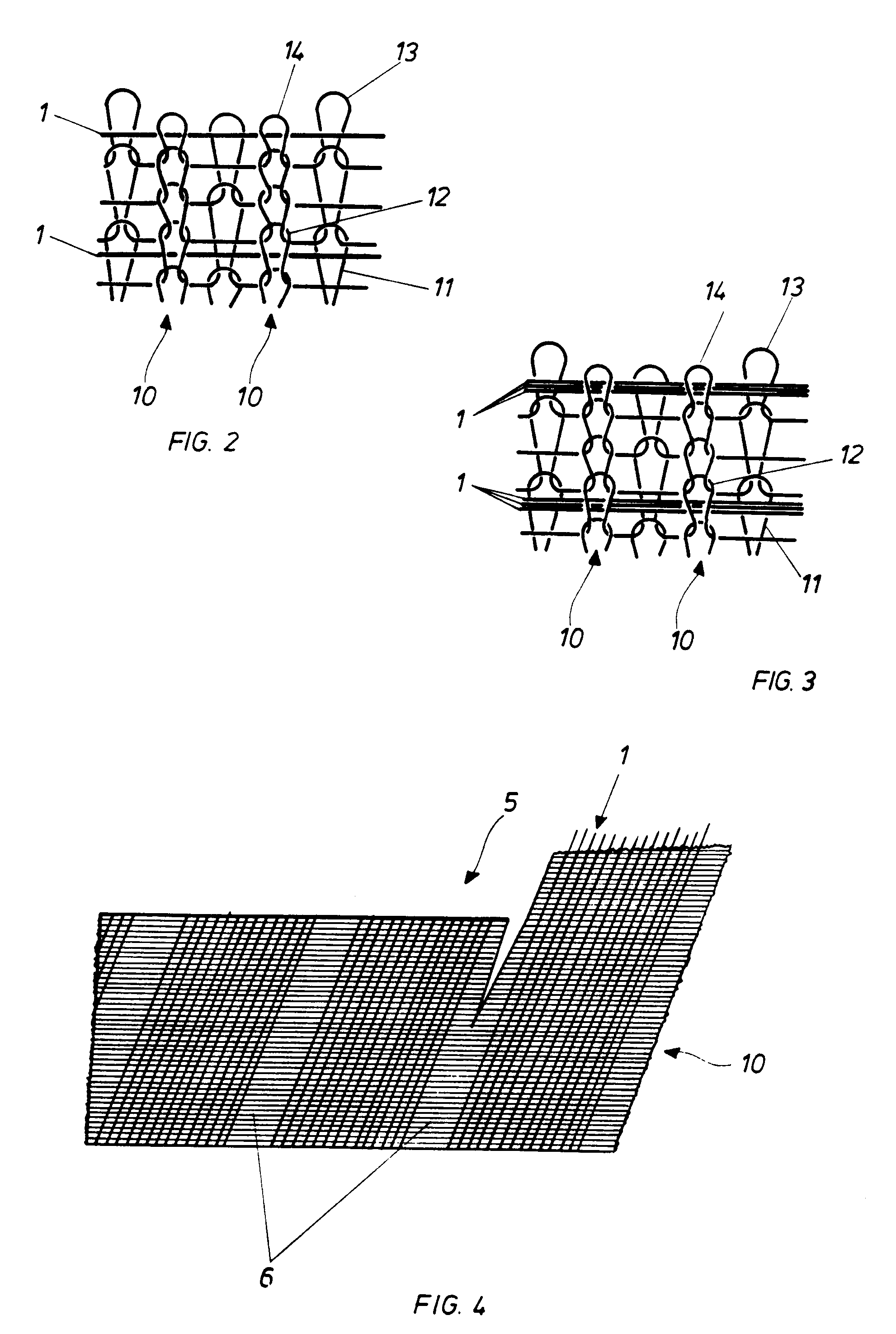
| (45) |
Mention of the grant of the patent: |
|
13.10.1993 Bulletin 1993/41 |
| (22) |
Date of filing: 09.02.1989 |
|
| (86) |
International application number: |
|
PCT/FI8900/020 |
| (87) |
International publication number: |
|
WO 8907/673 (24.08.1989 Gazette 1989/20) |
|
| (54) |
AN ORIENTED FIBRE STRUCTURE AND A METHOD FOR MANUFACTURING IT
STRUKTUR MIT ORIENTIERTEN FASERN UND VERFAHREN ZUR HERSTELLUNG
STRUCTURE A FIBRES ORIENTEES ET PROCEDE DE FABRICATION D'UNE TELLE STRUCTURE
|
| (84) |
Designated Contracting States: |
|
AT BE CH DE FR GB IT LI LU NL SE |
| (30) |
Priority: |
09.02.1988 FI 880571
|
| (43) |
Date of publication of application: |
|
28.11.1990 Bulletin 1990/48 |
| (73) |
Proprietor: SAARIKETTU, Jukka, Elias |
|
67200 Kokkola (FI) |
|
| (72) |
Inventor: |
|
- SAARIKETTU, Jukka, Elias
67200 Kokkola (FI)
|
| (74) |
Representative: Lauw, Rudolf C. W.,Dipl.-Ing., Dipl.-Wirtschaftsing. et al |
|
Karwinskistrasse 1
81247 München
81247 München (DE) |
| (56) |
References cited: :
GB-A- 2 121 837
US-A- 3 201 954
|
GB-C- 1 258 238
|
|
| |
|
|
|
|
| |
|
| Note: Within nine months from the publication of the mention of the grant of the European
patent, any person may give notice to the European Patent Office of opposition to
the European patent
granted. Notice of opposition shall be filed in a written reasoned statement. It shall
not be deemed to
have been filed until the opposition fee has been paid. (Art. 99(1) European Patent
Convention).
|
[0001] The present invention concerns a laminated oriented fibre structure according to
the precharacterizing part of claim 9 and a corresponding method for manufacturing
it according to the precharacterizing part of claim 1.
[0002] Here laminate means various kinds of fibre composites in general.
[0003] In accordance with known technology, glass-fibre composite is manufactured by spreading
resin on a glass-fibre mat that has been placed on top of or inside a mould. The glass-fibre
can be bound into a glass-fibre mat as discontinuous fibres, or woven into a blanket
structure. The problem with these is that air-bubbles tend to remain in the laminate.
This phenomenon is especially problematic at corners. One blanket structure is known
from the German patent application publication DE 3.304.345. US publication 3.201.104
shows a circular knitting machine, in which metal wire, intended to reinforce a hose,
is bound into knitted fabric. In this, however, the fabric is a fairly loose net.
If the fabric is drawn tight, the reinforcing wire or fibre will not remain straight,
on account of which it is not suitable for glass-fibre, for instance, which loses
its strength when bent.
[0004] In document GB-A-1 258 238 it is disclosed a resin laminate reinforced with a warp-knitted
fabric comprising laid-on reinforcing threads.
[0005] This invention is intended to create a new type of laminated fibre structure, which
can be easily formed to the surface of a mould, and which avoids the afore mentioned
air-bubbles in a laminate. By means of the invention, it is also advantageous to use
the so-called prepreg or commingled method, in which the binder is contained in the
support fibre or fed next to it, so that when it is heated it hardens in the knittinginto
a thin shell structure. It is possible to use polyester fibre as one kind of binder.
Because the support fibres are often of an elastic material, the knitted fibre draws
together so that the inelastic reinforcing fibres project from the fabric. This can
be controlled by means of the method in accordance with Patent Claim 8, in which openings,
from which the reinforcing fibre is made to protect, are left at regular intervals
in the knitted fabric. The principal advantages of the invention can be listed as
follows:
- by means of a suitable choice of support fibre filament and reinforcing fibre filament
materials a very low specific weight can be achieved,
- by means of a suitable choice of support fibre filament (e.g. polyester) an excellent
moisture absorption ability can be achieved, in which case there is little formation
of air-bubbles in the laminate,
- in textile products the direction of the oriented fibres can be seen immediately,
in which case it is easy to place the oriented glass-fibre filaments, which have a
high strength, in such a way that they carry most of the load that the laminate is
intended to withstand,
- the knitted fabric containg the reinforcing fibres is elastic or flexible in every
direction, so that it is easy to laminate it and especially to place it on a form
corresponding to its use,
- a hose-like knitted element can easily be cut both across and with the direction of
the oriented fibres, which makes it possible to use the knitted element as a sheet
element of a desired shape and/or size, and
it is also intended to create a fibre structure that can be used for various protective
purposes. In addition, the invention is intended to create a method of manufacturing
the fibre structure that can be used for any fibre at all that is required to be oriented.
The principal characteristics of the method in accordance with the invention appear
in the accompanying Patent Claim 1. The main principle of the invention is the binding
of the reinforcing fibres to a double-sided knitted fabric, in a transverse direction
to the wales. The application in accordance with Patent Claim 2 firstly makes it possible
to achieve a great output in production, and secondly makes possible the manufacture
of a product in accordance with Patent Claim 10. This kind of tube-like fibre structure
is particularly advantageous as, during lamination, it can be drawn directly onto
a pipe, pin, or corresponding form. Generally, both support fibres and reinforcing
fibres are filament fibres, i.e. endless fibres.
[0006] The method in Patent Claim 3 is used to create dense knitting with reinforcing fibres.
The form of application in Patent Claim 3 has the particular advantage that when resin
is effectively sucked into the fabric, it is unlikely that air-bubbles will form.
Many reinforcing fibres do not withstand knots at all. The strength of aramide fibres,
on the other hand, is retained even after they have been bent to a reasonable extent,
in which case the entire fibre structure can be knitted with this fibre. Similar experiments
are also being made with spun glass-fibre.
[0007] In place of only a single reinforcing fibre, it is naturally possible to use several
reinforcing fibres, i.e. bunches of fibres. On the other hand, it is not necessary
to feed reinforcing fibres to every course of loops. In this connection - there is
no problem in using as the reinforcing fibre any known fibre, for example glass, carbon,
aramide, borax, and ceramic fibre, either as filaments or as bunches of filaments.
It is also possible to use polyamides and their derivatives as reinforcing fibres.
In what follows the invention is illustrated by means of examples by referring to
the accompanying figures, in which
- Figure 1
- shows an enalarged picture of the knitted fabric in accordance with the invention
- Figure 2
- shows an enlargement of another knitted fabric
- Figure 3
- shows an enlargement of a third kind of knitted fabric
- Figure 4
- shows a hose-like knitted fabric
The knitted fabric shown in Figure 1 is created with a so-called double circular
knitting machine, in which there are vertical cylinder needles and horizontal plate
needles. Generally it is possible to speak of the first set of needles and the second
set of needles, the first of which knits the right way round and the second knits
the wrong way round. Polyester or other fibre is used as the base support fibre 7
i.e. as the loop filament. The needles on the cylinder side are set to knit on every
feed, i.e. the loops 2 in the course. The needles on the plate side, on the other
hand, are set to knit in the so-called interlock setting, in which case in the consecutive
feeding knitting takes place reciprocally. The loops knitted by the plate needles
are marked with the reference numbers 3 and 4. The reinforcing fibre 1 is fed to every
second course and it remains in the channels formed by loops 2, 3, 4 in different
directions. The reinforcing fibres 1 remain transverse to the direction of the wales
10. Because of the interlock setting, the knitted fabric tends to contract longitudinally,
in which case the reingforcing fibres become very dense. The possible projection of
the reinforcing fibres is controlled by removing needles from the set of plate needles
at regular intervals, so that the reinforcing fibre projects from the gaps that arise.
Surprising advantages in lamination are gained with this kind of knitted fabric. Because
of the projecting loops of reinforcing fibres, the direction of the fibres is tri-axial,
which prevents the delamination of the finished reinforcing structure, in other words,
the separation of its layers from each other.
[0008] Naturally it is possible for the support fibre structure to deviate from the above
in many ways. The knitted fabric must have, however, loops that are formed in both
directions, both "right-way round" and "wrong-way round", so that the reinforcing
fibre can be led between them. Reinforcing fibres can also be knitted into a very
loose smooth knitted fabric. The diameters of the cylinders of knitting machines in
general use range from 5/8'' to 36''. By using a larger machine it is possible to
efficiently manufacture wide fibre mats, as the hose can be cut open and spread out
as a mat. For example, a 36'' machine can make fibre cloth about 2.8 metres wide.
During lamination alternating layers can be placed cross-wise, so that the strength
of the laminate is equally great in all directions. On the other hand, it is very
easy to achieve the lamination of hose-like products with a hose-like fibre structure.
A spiral direction for the reinforcing fibres is exactly right when considering, for
example, pressure loading.
[0009] In the second advantageous form of realization of the invention the oriented reinforcing
fibres 1 run in the way shown in Figure 2 above and below the loops 13 and 14 of the
support fibres in a straight direction and parallel to one another in the channel
formed between the courses 11 and 12 every third course, this being perpendicular
to the wales 10 in such a way that each right-way round loop 14 of the courses 11
and 12 that contain the support fibres 2 enclose beneath them one reinforcing fibre
1. In order to achieve this kind of support fibre filament arrangement an amount of
support fibre filaments corresponding to the course number 1/4 is used in a circular
knitting machine. The filaments are led to the needle ring from feeding points located
peripherically at regular intervals. A quantity of loop fibre filaments corresponding
to 3/4 are led from the feeding points situated at regular intervals on the needle
ring. When the course number is the above-mentioned 36, there are 9 support fibre
filaments and 27 loop fibre filaments. In the knitted element then produced, a number
of the first and second courses 11 and 12 are knitted together without the support
fibre 1 being dropped between them. In the direction of the wales 10, each course
11, 12 containing support fibre 1 is followed by at least one course without a support
fibre filament.
[0010] Figure 3 shows still one more adavantageous knitted element already touched on in
the previous form of application, which is formed according to the second form of
realization of the invention, with the difference that in place of one support fibre
1, several, in this case three, parallel support fibre filaments are laid from one
feeding point at a time on top of the first course 11. Thus in this case each course
11, 12 containing several parallel support fibres 1 are followed, in the direction
of the wales 100, by two support fibre courses that have no support fibre filaments.
In a corresponding manner, binder fibres can be laid together with the reinforcing
fibre.
[0011] Figure 4 shows a hose-like knitted fabric 5, from which a ribbon-like fibre structure
is obtained. The hose-like fabric 5 is divided into narrow strips 6, to which no reinforcing
fibre is fed. The knitted fabric can easily be cut open at the edge of the strip 8
and thus the above-mentioned ribbon-like product can be obtained. Figure 4 shows clearly
that the wales 10 run perpendicularly in the hose-like fabric, whereas the reinforcing
fibres 1 run round the fabric in a spiral.
[0012] In one test knitted fabric the ratio of glass-fibre and polyester filaments was about
50/50. In this way a low specific weight was achieved for the laminate, only 1.3 g/cm³.
The theoretical density of a hollow sphere with a diameter of 100 mm and a wall thickness
of 2.5 mm would be about 0.2 g/cm³ with this laminate.
[0013] A method, in which the fibre is first treated so that when at rest it assumes a spiral
or twisted form, so that in the finished product it tends to contract, can be applied
especially to aramides. In this way it is possible to make the knitted fabric elastic
also in the direction of the reinforcing fibres.
1. A method for the manufacture of an oriented fibre structure to be laminated, in which
reinforcing fibres (1) are bound to form an oriented fibre mat or corresponding knitted
element, by which the fibres (1) are laminated inside resin or other binder and thus
a strong shell structure is formed,
characterized in that the knitting is carried out on a so-called double circular knitting machine,
in such a way that the knitting includes the following sequential and continually
repeating stages in manufacture,
a) the first loop (2) is made by the first set of needles,
b) at least one reinforcing fibre (1) to be included in the knitted fabric is oriented
and laid on top of the above-mentioned first loop, and
c) a second loop (3, 4) is knitted by the second set of needles on top of the oriented
reinforcing fibre and attached to the above-mentioned first loop (2),
in which case the oriented reinforcing fibre (1) runs with the support of the loops
(2, 3, 4) and straight between the courses in the channel formed by them.
2. A method of manufacture in accordance with Patent Claims 1, characterized in that the needles on the cylinder side are essentially arranged to knit in each
feed and the dial or corresponding needles are arranged to reciprocally by-pass, i.e.
they are set to the so-called interlock position, so that the knitted fabric is made
to contract longitudinally.
3. A method of manufacture in accordance with any of Patent Claims 1 - 2, characterized in that polyester or other fibre that absorbs resin well is used as the support fibre
(7).
4. A method of manufacture in accordance with any of Patent Claims 1 - 3, characterized in that more that one fibre (1) is laid in parallel on top of the above-mentioned
first loop (2).
5. A method of manufacture in accordance with any of Patent Claims 1 - 4, characterized in that a part of the courses of the above-mentioned first and second loops (2, 3,
4) are knitted together without the above-mentioned support fibre filament being laid
between them.
6. A method of manufacture in accordance with any of Patent Claims 1 - 7, characterized in that aramide or spun glass-fibre is used as the support fibre (7).
7. A method of manufacture in accordance with any of Patent Claims 1 - 6, characterized in that the support fibre contains binder for lamination, which is made to react
by the effect of heat or in some other manner, and which then makes it possible to
manufacture a strong shell structure by means of the so-called prepreg method.
8. A method of manufacture in accordance with any of Patent Claims 1 - 5, characterized in that one needle has been removed at regular intervals from one side, most advantageously
from the plate needles' side, in which case the reinforcing fibre is made to project
from the opening thus created in the knitted fabric.
9. An fibre structure to be laminated, in which reinforcing fibres (1) are bound to form
an oriented fibre mat or corresponding knitted element, by means of which the fibres
(1) are laminated inside resin or other binder and thus form a strong shell structure,
characterized in that the reinforcing fibre (1) in the transverse direction is bound to the smooth
knitted fabric formed by the right-side loops (2) by means of the wrong-side loops
(3, 4).
10. A knitted fibre structure in accordance with Patent Claim 9, characterized in that the knitted fabric (5) is hose-like, in which the reinforcing fibres (1)
run in a continuous spiral round the knitted fabric (5).
11. A knitted hose-like fibre structure in accordance with Patent Claim 10, characterized in that there is a narrow spiral strip (6) without reinforcing fibre (1) between
the spirally circulating reinforcing fibres (1), by means of which the hose-like knitted
fibre (5) can be cut open to form a ribbon.
12. A fibre structure in accordance with any of Patent Claims 1 - 11, characterized in that the reinforcing fibres, for example aramide fibres, have been coiled, so
that the fibre structure is elastic also in the direction of the fibres.
1. Ein Verfahren zur Herstellung einer zu laminierenden orientierten Faserstruktur, in
der Verstärkungsfasern (1) eine orientierte Fasermatte oder ein entspechend gestricktes
Element bilden sollen, wodurch die Fasern (1) in einem Harz oder einem anderen Bindemittel
laminiert sind, um auf diese Weise eine starke Schalen- bzw. Rippenstruktur zu bilden,
dadurch gekennzeichnet, daß das Stricken auf einer sogenannten Doppel-Rund-Strickmaschine in der Weise durchgeführt
wird, daß das Stricken folgende aufeinanderfolgende und sich kontinuierlich wiederholende
Herstellungsstufen umfaßt,
(a) die erste Schlaufe (2) wird durch einen ersten Nadelsatz hergestellt,
(b) wenigstens eine in das gestrickte Gewebe einzufügende Verstärkungsfaser (1) wird
orientiert und auf die Oberseite der vorstehend erwähnten ersten Schlaufe gelegt,
und
(c) eine zweite Schlaufe (3,4) wird durch einen zweiten Nadelsatz auf der Oberseite
der orientierten Verstärkungsfaser gestrickt und an der ersten Schlaufe (2) befestigt,
wobei die orientierte Verstärkungsfaser (1) mit Unterstützung der Schlaufen (2,3,4)
und zwischen den Maschenreihen in dem durch sie gebildeten Kanal gerade verläuft.
2. Ein Herstellungsverfahren nach Anspruch 1, dadurch gekennzeichnet, daß die Nadeln an der Zylinderseite im wesentlichen so angeordnet sind, daß sie
bei jedem Vorschub stricken, und daß die Rippscheibe oder die entsprechenden Nadeln
so angeordnet sind, daß sie abwechselnd aneinander vorbeigehen, das heißt, sie werden
in sogenannte Interlock-Position gesetzt, so daß sich das gestrickte Gewebe in Längsrichtung
zusammenzieht.
3. Ein Herstellungsverfahren nach Anspruch 1 oder 2, dadurch gekennzeichnet, daß Polyester oder eine andere Faser, die Harz gut absorbiert, als Tragfaser (7)
verwendet werden.
4. Ein Herstellungsverfahren nach einem der Ansprüche 1 bis 3, dadurch gekennzeichnet, daß mehr als eine Faser (1) parallel auf die Oberseite der ersten Schlaufe (2) gelegt
wird.
5. Ein Herstellungsverfahren nach einem der Ansprüche 1 bis 4, dadurch gekennzeichnet, daß ein Teil der Maschenreihen der ersten und zweiten Schlaufen (2,3,4) miteinander
verstrickt werden, ohne daß der oben genannte Tragfaserfaden zwischen sie gelegt wird.
6. Ein Herstellungsverfahren nach einem der Ansprüche 1 bis 5, dadurch gekennzeichnet, daß Aramid oder versponnene Glasfaser als Tragfaser (7) verwendet wird.
7. Ein Herstellungsverfahren nach einem der Ansprüche 1 bis 6, dadurch gekennzeichnet, daß die Tragfaser Bindemittel zur Lamination enthält, was durch die Wirkung von
Hitze oder in anderer Weise zum Reagieren gebracht wird, und das es dann möglich macht,
eine starke Schalen- bzw. Rippenstruktur mit Hilfe des sogenannten Kunststoffimprägnier-Verfahrens
(Prepreg-Verfahrens) herzustellen.
8. Ein Herstellungsverfahren nach einem der Ansprüche 1 bis 5, dadurch gekennzeichnet, daß eine Nadel in regelmäßigen Intervallen von einer Seite entfernt wurde, höchst
vorteilhafterweise von der Plattennadelseite, wobei die Verstärkungsfaser dazu gebracht
wird, von der auf diese Weise in dem gestrickten Gewebe erzeugten Öffnung hervorzustehen.
9. Eine zu laminierende Faserstruktur, in der Verstärkungsfasern (1) eine orientierte
Fasermatte oder ein entsprechend gestricktes Element bilden sollen, wodurch die Fasern
(1) innerhalb von Harz oder einem anderen Bindemittel laminiert werden und somit eine
starke Schalen- bzw. Rippenstruktur bilden, dadurch gekennzeichnet, daß die Verstärkungsfaser (1) in Querrichtung mit dem glatt gestrickten Gewebe verbunden
ist, das durch die rechts-seitigen Schlaufen (2) mittels der falsch- bzw- links-seitigen
Schlaufen (3,4) gebildet ist.
10. Eine gestrickte Faserstruktur nach Anspruch 9, dadurch gekennzeichnet, daß das gestrickte Gewebe (5) schlauchartig ist, in dem die verstärkten Fasern (1)
in einer kontinuierlichen Spirale rund um das gestrickte Gewebe (5) herum verlaufen.
11. Eine gestrickte schlauchartige Faserstruktur nach Anspruch 10, dadurch gekennzeichnet, daß ein enger Spiralstreifen (6) ohne Verstärkungsfaser (1) zwischen den spiralig
zirkulierenden Verstärkungzfasern (1) vorgesehen ist, wodurch das schlauchartig gestrickte
Gewebe (5) aufgeschnitten werden kann, um ein Band zu bilden.
12. Eine Fazerstruktur nach einem der Ansprüche 1 bis 11, dadurch gekennzeichnet, daß die Verstärkungsfasern, zum Beispiel Aramid-Fasern, gewendelt wurden, so daß
die Faserstruktur auch in Faserrichtung elastisch ist.
1. Procédé de fabrication d'une structure à fibres orientées à laminer, dans laquelle
des fibres de renforcement (1) sont liées pour former une natte de fibres orientées
ou un élément tricoté correspondant par lequel les fibres (1) sont laminées dans de
la résine ou un autre liant pour former une structure en carcasse forte,
caractérisé en ce que le tricotage est effectué sur un métier dit circulaire double d'une telle
manière que le tricotage comprenne les étappes de fabrication séquentielles et continuellement
répétées suivantes:
a) la première maille (2) est effectuée par le premier jeu d'aiguilles,
b) au moins une fibre de renforcement (1) à incorporer dans l'étoffe tricotée est
orientée et posée sur la première maille sus-mentionée, et
c) une deuxième maille (3, 4) est tricotée par le second jeu d'aiguilles sur la fibre
de renforcement orientée et attachée à la première maille sus-mentionnée (2),
dans lequel cas la fibre de renforcement orientée (1) court avec le support des mailles
(2, 3, 4) et tout droit entre les files de mailles dans le canal formé par ces dernières.
2. Procédé de fabrication selon la revendication 1, caractérisé en ce que les aiguilles côté cylindre sont disposées essentiellement pour tricoter
dans chaque trou d'alimentation et que le disque ou les aiguilles correspondantes
sont disposées de telle sorte à passer l'une à côté de l'autre, c.à.d. qu'elles sont
réglées dans la position dite interlock, de sorte que l'étoffe tricotée est faite
pour se contracter longitudinalement.
3. Procédé de fabrication selon l'une des revendications 1 à 2, caractérisé en ce qu'une fibre polyester ou une autre fibre absorbant bien la résine est utilisée
comme fibre de support (7).
4. Procédé de fabrication selon l'une des revendications 1 à 3, caractérisé en ce que plus d'une libre (1) est posée en parallèle sur la première maille sus-mentionnée
(2).
5. Procédé de fabrication selon l'une des revendications 1 à 4, caractérisé en ce qu'une partie des files des premières et deuxièmes mailles sus-mentionnées
(2, 3, 4) sont tricotées ensemble sans que le filament de la fibre de support soit
posé entre eux.
6. Procédé de fabrication selon l'une des revendications 1 à 5, caractérisé en ce qu'une fibre d'aramide ou de verre filé est utilisée comme fibre de support
(7).
7. Procédé de fabrication selon l'une des revendications 1 à 6, caractérisé en ce que la libre de support contient un liant pour la lamination de telle nature
qu'il réagisse sous l'effet de la chaleur ou d'une autre manière de telle sorte à
rendre possible la fabrication d'une structure en carcasse forte au moyen du procédé
dit Prepeg.
8. Procédé de fabrication selon l'une des revendications 1 à 5, caractérisé en ce que une aiguille a été retirée à intervalles réguliers de l'un des côtés, de
préférence du côté de la plaque à aiguilles, dans lequel cas la fibre de renforcement
est faite pour projeter de l'ouverture ainsi créée dans l'étoffe tricotée.
9. Structure à libres à laminer, dans laquelle des fibres de renforcement (1) sont liées
pour former une natte de libres orientées ou un élément tricoté correspondant, par
lequel les fibres (1) sont laminées dans de la résine ou un autre liant pour former
une structure en carcasse forte, caractérisé en ce que la libre de renforcement en direction transversale est liée au moyen des
mailles envers (3, 4) à l'étoffe tricotée souple formée par les mailles endroit (2).
10. Structure de fibres tricotée selon la revendication 9, caractérisé en ce que l'étoffe tricotée (5) ressemble à une gaine dans laquelle les fibres de
renforcement (1) courent dans une spirale sans fin autour de l'étoffe tricotée (5).
11. Structure de fibres tricotées en forme de gaine selon la revendication 10, caractérisé en ce qu'il y a une bande étroite en spirale sans fibre de renforcement (1) entre
les fibres de renforcement circulant en spirale (1), au moyen duquel la fibre tricotée
en forme de gaine (5) peut être coupée pour former un ruban.
12. Structure de fibres selon l'une des revendications 1 à 11, caractérisé en ce que les fibres de renforcement, par exemples des fibres en aramide, ont été
enroulées, de façon à ce que la structure de fibres soit également élastique dans
la direction des fibres.