|
(11) | EP 0 409 982 B1 |

| (12) | EUROPEAN PATENT SPECIFICATION |
|
|
| (54) |
CONTROL UNIT FOR INJECTION MOLDING MACHINES REGELEINHEIT FÜR EINSPRITZGIESSVORRICHTUNG UNITE DE COMMANDE POUR MACHINES DE MOULAGE A INJECTION |
|
|
|||||||||||||||||||||||||||||||
| Note: Within nine months from the publication of the mention of the grant of the European patent, any person may give notice to the European Patent Office of opposition to the European patent granted. Notice of opposition shall be filed in a written reasoned statement. It shall not be deemed to have been filed until the opposition fee has been paid. (Art. 99(1) European Patent Convention). |
[0001] The present invention relates to apparatus for control of an injection molding machine which injects a melted resin into the cavity of a mold to form plastic moldings.
[0002] In an injection molding machine, a plastic material plasticized in an elongated cylinder is injected through a nozzle by rotational movement of a screw to fill the cavity of a mold with the plastic material. Thereafter, when the plastic material in the mold is cooled and set, the molding is taken out by opening the mold.
[0003] A programmed injection process which controls the injection velocity is known as a conventional technique according to an injection control method in an injection molding machine of this type. This method includes instead controlling the moving velocity of the screw in order to control the injection velocity from the nozzle, namely, the flow velocity of the resin into the mold wherein the moving velocity of the screw is controlled in a plurality of stages. This technique is disclosed in, for example, JP-A-48-95458 and JP-A-59-64337.
[0004] In these conventional techniques, however, since the diameter of the nozzle opening is constant, a change in the injection velocity causes the heating value produced by shearing of the resin at the nozzle to be changed. Thus even if only the injection velocity is desired to be changed, the resin temperature is also changed together, so that the controlled factors are complicated and control is difficult.
[0005] Another conventional technique (JP-A-60-242022) discloses a throttled path portion provided at the nozzle end. The opening of the throttled path portion is changed in injection to change the heating value produced by shearing at the nozzle to thereby provide a desired resin temperature. In order to only eliminate uneven distribution of temperature of the resin varying depending on the position of the screw stroke, this technique to variably controls the opening of the nozzle valve in accordance with the position of the screw to thereby maintain the temperature of the injected resin at a constant temperature. However, in order to provide such control, it is necessary to accurately understand at all times the distribution of the resin temperature along the axis of the screw before the injection step starts. To this end, a troublesome pre-process must be performed which includes sensing the distribution of the resin temperature, knowing the average distribution of temperature by many experiments, etc., so that this technique is problematic from a standpoint of accurate control of temperature, working efficiency and practicality.
[0006] For control of even resin temperature in injection molding, the factors which change the resin temperature include the temperature of a mold used in addition to the heating due to shearing at the nozzle section which is due to a change in the injection velocity. If the temperature of the mold fluctuates, the temperature of the melted resin filled in the cavity fluctuates correspondingly, the specific volume of the resin also fluctuates, and hence the resulting product fluctuates in dimension.
[0007] As a prior art which has percieved the temperature of a mold, there is known a molding control method which includes the steps of calculating the correlation between the the temperature (or the resin temperature) and the resin pressure, sensing the actual mold temperature (or the actual resin temperature) in the injection molding and controlling the resin pressure. For example, the pressure is decreased in order to decrease the resin pressure by a quantity corresponding to a decrease in the mold temperature (or the resin temperature).
[0008] Such molding control method is much troublesome, its accuracy is low and not an optimal molding control method. Namely, if the resin pressure is changed, the distribution of internal stress in the mold will change and bad products may result undesirably.
[0009] If the mold temperature (or resin temperature) fluctuates, it is conceivable to control the temperature of the housing in accordance with that fluctuation to directly correct the resin temperature, but the temperature responsive rate of the housing is greatly low compared to molding cycle rate, so that such control is not effective practically.
[0010] If the mold temperature is controlled precisely so as not to fluctuate, stabilized molding can be performed. However, the mold temperature varies depending on the atmospheric temperature, so that the temperature within a factory in which the injection molding machine is installed must be controlled at a constant temperature in order to control the mold temperature precisely, and therefore the control would be expensive and not practical. EP 0 262 229 which is to be considered as comprised in the state of the art according to Article 54 (3) EPC describes a control apparatus for an injection molding machine which injects a melted resin within a housing into a cavity of a mold through a nozzle at a housing end by movement of a screw, comprising
nozzle opening changing means for variably driving the throttle path area of the nozzle,
sprue velocity changing means for controlling the moving velocity of the screw, and
controlling means for controlling the nozzle opening changing means.
[0011] The controlling means controls the drive of the nozzle opening changing means by comparing the detection signals received from an injection screw position detector and an injection screw travel speed detector with a preset injection screw position signal and a preset injection screw travel speed signal.
[0012] It is an object of the present invention to provide a control apparatus for an injection molding machine which is capable of controlling the injection velocity and the resin temperature separately to thereby facilitate the molding operation, and to manufacture precise and uniform moldings.
[0014] The control apparatus of the present invention is capable of maintaining the specific volumes of resin uniformly at all times at injection, irrespective of fluctuations of the mold temperature and provides precise stabilized moldings successively.
[0015] In the present invention, the nozzle opening is variably controlled in accordance with a change in the mold temperature to change the frictional heat (the heating value produced by shearing) of the resin passing through the nozzle to thereby maintain the specific volumes of the resin at a constant value at all times irrespective of changes in the mold temperature and to precisely stabilize the qualities of moldings succesively and to reduce the cost. When the mold temperature is low compared to a preset reference temperature, the area of the nozzle opening is decreased while when it is high, the area of the opening is increased to thereby control the frictional heat of the melted resin passing through the nozzle.
[0016] Fig. 1 is a control block showing a first embodiment of the present invention; Fig. 2 is a graph showing the relationship between increasing temperature of the resin and flow velocity of the resin passing through the nozzle; Fig. 3 is a partial cross section view of the detailed structure of a mold; Fig. 4 is a control block diagram showing a second embodiment of the present invention; Fig. 5 is a control block diagram of a third embodiment present invention; Fig. 6 is a control block diagram of a fourth embodiment present invention; Fig. 7 is a control block diagram of a fifth embodiment present invention; and Fig. 8 is a control block diagram of a sixth embodiment present invention.
[0017] The present invention will now be described in detail with respect to one embodiment thereof shown in the accompanying drawings.
[0018] Fig. 1 shows a first embodiment of the present invention. The injection apparatus includes a cylindrical housing 1 in which a screw 2 is inserted slidably and rotationally such that a resin 20 within a hopper 3 is melted and that the cavity 6 of a mold 5 is filled with the melted resin injected through the nozzle 4. The screw 2 is coupled to a piston rod 8 in an injection cylinder 7. A drive shaft 10 rotated by a hydraulic motor 9 is splined to the piston rod 8 to thereby rotate the screw 2 and move same in the direction of injection.
[0019] The nozzle 4 has a flow velocity control mechanism which controls the opening area of the nozzle, for example, a nozzle valve 11 which is coupled through a link mechanism including a lever 12 and a rod 13 to a nozzle valve driver, for example, a proportional solenoid 14. By controlling an electric current supplied to the solenoid 14, the opening of the nozzle valve 11 is changed to thereby control the opening area of the nozzle 4. Reference numeral 15 denotes a check valve.
[0020] A hydraulic oil is fed to the injection cylinder 7 from a pump 21 via a flow control valve 22 and a directional changeover valve 23. The flow control valve 22 is an electromagnetic type flow velocity control valve which variably controls a flow velocity of oil which supplied to the cylinder 7 in accordance with an electrical command issued by an injection velocity setting unit 30 to thereby generate a screw velocity corresponding to the input command.
[0021] Set at the injection velocity setting unit 30 are three screw velocities V1, V2 and V3 in the instant case such that the screw velocity can be controlled variably in three stages of V1, V2 and V3 in a single injection process. The output from the injection velocity setting unit 30 is also input to a valve opening computing control unit 35 in addition to the flow control valve 22.
[0022] The valve opening computing control unit 35 calculates the opening of the nozzle valve corresponding to the screw velocity, data on which the control unit 35 has received, and provides the result of the calculation to the nozzle valve driver 14 to variably control the opening of the nozzle valve 11. Before describing the detailed structure of the control unit 35, the principle of the invention will be described.
[0023] As mentioned above, when the melted resin 20 to be injected passes through the nozzle 4, its temperature is increased due to frictional heat. The frictional heat ΔT is given by the following equation (1):
where
A is the thermal equivalent of work;
W is the specific volume of the resin at an absolute temperature of 0° K;
Cp is a specific heat at constant pressure; and
ΔP is the difference in pressure through the throttled path portion.
[0024] The flow velocity (injection velocity) VR of the resin passing through the throttled path portion 4 is given by
where a and 1/n are constants determined by the resin.
[0026] Therefore, the frictional heat ΔT of the melted resin at the throttled path portion is represented by the product of a proportional constant K and the nth power of the flow velocity VR of the resin passing through the nozzle.
[0027] In the injection molding machine, the flow velocity (injection velocity) VR of the resin at the nozzle section 4 due to the movement of the screw 2 within the housing 1 is given by
where
AS is the sectional area of the housing,
VS is the moving velocity of the screw, and
AN: the throttled path area of the nozzle.
[0029] It will be understood from equation (5) that if the screw diameter (the sectional area AS of the housing) and the resin characteristics (W, Cp, a, 1/n) are determined, the heating value ΔT produced in the melted resin passing through the nozzle 4 is determined by the moving velocity of the screw VS and the trottled path area of the nozzle AN.
[0030] Fig. 2 show experimental data on the relationship between ΔT and VR with five kinds of resins such as GPGS, ABS, etc., used as parameters wherein VR is calculated using equation (4) and Ts show the respective actual temperatures of the resins.
[0031] It is well-known in the injection molding machine that the injection velocity VR of the resin at the nozzle (the flow velocity per unit hour of the resin passing through the nozzle valve) and the temperature T of the melted resin greatly influence the appearance, etc., of moldings. As will be seen in the second graph, if the injection velocity PR is changed, the resin temperature T is also changed, so that VR and T cannot be controlled separately by regular control.
[0032] In equation (5), the frictional heat ΔT at the nozzle section is given as a ratio of the screw moving velocity VS to the throttled path area of the nozzle AN. The screw moving velocity VS is proportional to the injection velocity VR. Therefore, in order that the resin temperature T is maintained constant irrespective of changes in the injection velocity VR, the throttled path area of the nozzle AN should be changed such that
in equation (5) in accordance with changes in the screw moving velocity VS. If VS increases, AN should be increased such that
whereas if VS decreases, AN should be decreased such that VS/AN becomes constant.
[0033] Thus it is possible to separately control the injection velocity VR and the resin temperature T as the respective independent parameters.
[0034] The above principle is the control performed in consideration of only the frictional heat at the nozzle section 4. As shown in Fig. 3, in the regular injection machine, the resin passing through the nozzle 4 into the mold 5 further passes through a sprue 16, a runner 17 and a so-called gate 18 having a reduced cross section area into the cavity 6.
[0035] Therefore, the total frictional heat value ΔT' of the frictional heat value ΔT at the nozzle section 4, and the frictional heat value ΔTa produced at the sprue, runner and gate is given by the following equation (6):
where
i = the number of throttled path portions at the sprue, runner and gate section, and
Ai is a respective one of the sectional areas of the throttled path portions of the sprue, runner and gate section.
[0036] Since in equation (6), β becomes constant if the mold is determined, ΔT' also becomes a function of AN and VS. If the throttled path area AN of the nozzle valve is controlled such that
is maintained constant even if the injection velocity VS changes, the temperature of the resin which passes through the gate section 18 into the cavity 6 can be controlled constant at all times.
[0037] While the above example presupposes that control is free from the influence of the mold temperature, the melted resin actually flows into the mold while being cooled by the mold. Therefore, when the injection velocity is low, the melted resin is further cooled and therefore, it is difficult to maintain constant the temperature of the resin flowing into the mold cavity 6 in spite of changes in the injection velocity by relying only on the above control. Therefore, if the injection velocity decreases, the nozzle area should be throttled by a quantity corresponding to a decrease in the resin temperature due to the mold cooling.
[0038] In more detail, control will be described using equation (6). Control should be provided which includes throttling the opening slightly more than the opening of AN which maintains
constant, namely, the control of the AN value such that
is maintained constant where γ is a value to cause an excessive heating value at the nozzle section.
[0039] While the above is intended to maintain the heating value constant, it is possible to control the heating value of the resin freely to a desired value for the screw velocity VS if
is controlled so as to be maintained constant and if the γ value is variably set simultaneously.
[0040] In the embodiment of the apparatus shown in Fig. 1, the resin temperature is maintained at a predetermined temperature by controlling variably the opening of the nozzle valve 11 in accordance with changes (V1, V2 or V3) in the moving velocity VS of the screw 2 on the basis of the principle mentioned above. In the injection process, the velocity signals V1 - V3 from the injection velocity setting unit 30 are also delivered sequentially to a nozzle valve opening control unit 35 where the throttled path area of the nozzle valve 4,
(Vn: V1, V2, V3), corresponding to the velocities V1 - V3 of the screw 2, are sequentially calculated and a command is given for the nozzle valve driver 14 to provide a quantity of ristriction corresponding to the value of AN. The method of setting the function
includes a process for determining AN so as to maintain VS/AN constant on the basis of equation (5), a process for determining AN so as to maintain
constant on the basis of equation (6) or a process for determining AN so as to maintain
constant. The constants α, β, γ, and 1/n necessary for calculation should be experimentarily calculated beforehand for setting the functions.
[0041] Since in the particular embodiment the opening of the nozzle valve 11 is variably controlled such that the resin temperature is maintained at a predetermined temperature in accordance with a change in the setting points V1 - V3 for the moving velocities of the screw 2, the temperature of the melted resin passing through the nozzle valve is automatically controlled and therefore the temperature of the melted resin flowing into the mold cavity is controlled with high operability. Since the molding temperature of the resin is high; namely, 350 - 500°C, in recent superempler molding, special materials are required for the housing 1 of the injection machine. In contrast, according to the particular embodiment, the temperature of the melted resin passing through the nozzle valve can be freely control. For example, the temperature of the melted resin within the housing 1 can be set at a low temperature; namely, at 300 - 350°C, to thereby achieve a desired molding temperature using the frictional heat produced by the resin. Thus, the housing temperature can be set low and it is unnecessary to use special materials for the housing to thereby perform inexpensive superempler molding. Since the heat generation by the resin is performed instantaneously at the nozzle valve, there is not problem about the stagnation of heat within the housing 1, and scorch, silvering, black streak, discoloration, deterioration, etc., can be prevented to thereby allow mass production which provides good products molded in a stabilized manner.
[0042] In the particular embodiment, the screw velocity VS is substituted for the injection velocity VR. The injection velocity VR means the velocity at which the resin flows into the mold cavity 6 from the nozzle 4, and the relationship between the injection velocity VR and the screw velocity VS is given by equation (4) as mentioned above;
The nozzle diameter may change in accordance with a mold used, in which case the screw velocity VS is substituted for the injection velocity VR.
[0043] Fig. 4 shows a second embodiment of the present invention. While in the first embodiment a setting point (a desired value) for the controlled screw velocity system is used as the screw velocity VS, the actual sensed value is used as the screw velocity VS in the second embodiment shown in Fig. 4.
[0044] The valve opening computing control unit 35 receives a sensed value indicative of the moving velocity VS of the screw 3 sensed by a screw velocity sensor 37 via an amplifier 36. The valve opening computing control unit 35 performs calculations similar to those mentioned above in accordance with the sensed value to calculate the screw opening AN corresponding to the sensed value, and controls the opening of the nozzle valve 11 variably in accordance with the calculated value to thereby maintain the resin temperature at a desired temperature.
[0045] Since in the injection molding machine the temperature of the resin passing through the nozzle valve 4 is raised due to frictional heat, it is possible to know the injection velocity VR indirectly by sensing the temperature T of the resin having passed through the nozzle valve 4. Therefore, arrangement may be such that by sensing the temperature of the resin having passed through the nozzle valve, a quantity of restriction to the nozzle valve 4 is controlled in accordance with the sensed value of the resin temperature.
[0046] In order to sense the resin temperature, (1) as shown in a third embodiment of Fig. 5, a resin temperature sensor 40 may be provided in the nozzle valve 4 or in the mold cavity 6; (2) as shown in a fourth embodiment of Fig. 6, a pressure sensor 45 may sense the difference between the pressures before and after the throttled path portion of the nozzle valve 4 or the difference between the pressure before the throttled path portion of the nozzle valve 4 and the pressure of the resin in the mold (pressure loss) to calculate the heating value due to friction of the resin, or (3) the heating value due to friction of the resin may be calculated from the injection velocity VR.
[0047] Fig. 7 shows a fifth embodiment of the present invention which includes a nozzle opening setting unit 50 in which setting points (three, in the particular case) AN₁, AN₂, and AN₃ are set for the nozzle opening AN in a single injection process to control the nozzle valve driver 14. The setting points AN₁ - AN₃ each are input to an injection velocity control unit 55 which performs an inverse conversion
of the operation
by the valve opening computing control unit 35 of the first embodiment. The input valve opening setting points AN₁, AN₂ and AN₃ each are converted to the corresponding screw velocities VS with the resin temperature maintained constant on the basis of the expression (5) or (6), and the converted values VS each are input to the flow control valve 22. The fifth embodiment includes mere replacement, with another one, of the relationship between the injection velocity setting unit 30 and the nozzle valve opening control unit 35 of the first embodiment to thereby provide effects similar to those provided by the first embodiment.
[0048] Fig. 8 shows a sixth embodiment of the present invention which includes a mold temperature sensor 60 provided in the mold 5. The sensed temperature T from the sensor 60 is delivered to a comparator 71 of a controller 70 where it is compared to a reference temperature T₀ set at a reference mold temperature setting unit 72. The deviation ε is delivered to a correction computing unit 73 to calculate a correction value using a correction coefficient k set at a correction coefficient setting unit 74 and a set opening AN at a nozzle valve opening setting unit 75 and delivers the resulting correction value to a controller 76, which then feeds a control current to the proportional solenoid 14 to change the opening of the nozzle valve 11.
[0049] Now the operation of the sixth embodiment will be described. First, the mold 5 is heated to a temperature set by a heater or the like built in the mold 5 and the nozzle valve 11 is controlled so as to have a set opening AN set at the nozzle valve opening setting unit 75.
[0050] The temperature of the mold 5 during molding is sensed by a mold temperature sensor 60, the output from which is then input to the controller 70. When the sensed temperature T is equal to a reference temperature T₀, the deviation ε is 0, so that the nozzle valve opening is equal to the set opening AN.
[0051] When the sensed temperature T is lower than the reference temperature T₀, a deviation ε is produced, so that the correction computing unit 73 calculates a correction value which reduces the set opening AN using a correction coefficient k to thereby cause the controller 76 to feed a control electric current to the proportional solenoid 14 in order to reduce the opening of the nozzle valve 11. Thus the opening area of the nozzle 4 is reduced, the resistance to flow of the melted resin and hence the frictional heat increase to raise the temperature of the melted resin to thereby increase the specific volume of the resin within the cavity 6.
[0052] When the sensed temperature T is higher than the reference temperature T₀, the opening of the nozzle valve 11 and hence the opening area of the nozzle 4 are increased to reduce the resistance to flow of the melted resin to thereby reduce the frictional heat generated and to reduce the specific volume of the resin in contrast with the case just mentioned above.
[0053] As just described above, in the sixth embodiment, a change in the mold temperature is sensed, the heating value of the resin produced frictionally which is a factor of the same temperature is controlled in accordance with the sensed change in the temperature, namely, the frictional heating value of the melted resin is changed by adjusting the opening area of the nozzle 4 to control the temperature of the melted resin to thereby maintain the specific volume of the resin constant, so that molding is performed precisely in a stabilized manner to thereby successively provide moldings with stabilized quality. Since the pressure of the melted resin is not controlled, the distribution of the stress within the mold does not change to thereby prevent the production of bad moldings. In this control operation, the opening area of the nozzle 4 is only required to be changed, so that control is easy. Furthermore, it is not necessary to control the room temperature in the factory constant at a constant value, so that the apparatus is inexpensive.
1. A control apparatus for an injection molding machine which injects a melted resin
within a housing (1) into a cavity (6) of a mold (5) through a nozzle (4) at a housing
end by movement of a screw (2),
comprising
nozzle opening changing means (11,12,13,14) for variably driving the throttle patch area AN of the nozzle (4),
screw velocity changing means (22) for controlling the moving velocity Vs of the screw (2), and
controlling means (35) for receiving the moving velocity Vs of the screw (2), for calculating the throttle path area AN of the nozzle (4) such that Vs/AN becomes constant corresponding to the velocity Vs, and for outputting the value AN thus calculated to the nozzle opening changing means (11,12,13,14).
comprising
nozzle opening changing means (11,12,13,14) for variably driving the throttle patch area AN of the nozzle (4),
screw velocity changing means (22) for controlling the moving velocity Vs of the screw (2), and
controlling means (35) for receiving the moving velocity Vs of the screw (2), for calculating the throttle path area AN of the nozzle (4) such that Vs/AN becomes constant corresponding to the velocity Vs, and for outputting the value AN thus calculated to the nozzle opening changing means (11,12,13,14).
2. A control apparatus according to claim 1, wherein the mold (5) includes a sprue (16),
a runner (17) and a gate (18), and wherein the controlling means (35) calculates the
throttle path area AN of the nozzle (4) such that
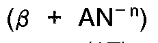
becomes constant, where β is the total sum of sectional areas in the sprue (16), the runner (17) and the gate (18), and n is a constant determined by the resin, and outputs the value AN thus calculated to the nozzle opening changing means (11,12,13,14).
becomes constant, where β is the total sum of sectional areas in the sprue (16), the runner (17) and the gate (18), and n is a constant determined by the resin, and outputs the value AN thus calculated to the nozzle opening changing means (11,12,13,14).
3. A control apparatus according to claim 1, wherein the mold (5) includes a sprue (16),
a runner (17) and a gate (18), and wherein the controlling means (35) calculates the
throttle path area AN of the nozzle (4) such that
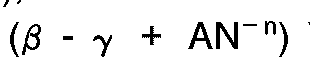
becomes constant, where β is the total sum of sectional areas in the sprue (16), the runner (17) and the gate (18), γ is the drop in resin temperature due to cooling down of the mold temperature, and n is a constant determined by the resin, and outputs the value AN thus calculated to the nozzle opening changing means (11,12,13,14).
becomes constant, where β is the total sum of sectional areas in the sprue (16), the runner (17) and the gate (18), γ is the drop in resin temperature due to cooling down of the mold temperature, and n is a constant determined by the resin, and outputs the value AN thus calculated to the nozzle opening changing means (11,12,13,14).
4. A control apparatus according to claim 1, wherein the controlling means (35) calculates
the throttle path area AN of the nozzle (4) such that
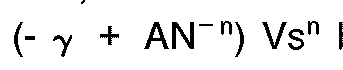
becomes constant, where γ is the drop in resin temperature due to cooling down of the mold temperature, and n is a constant determined by the resin, and outputs the value AN thus calculated to the nozzle opening changing means (11,12,13,14).
becomes constant, where γ is the drop in resin temperature due to cooling down of the mold temperature, and n is a constant determined by the resin, and outputs the value AN thus calculated to the nozzle opening changing means (11,12,13,14).
5. A control apparatus according to claim 1, wherein the moving velocity Vs of the screw
(2) inputted to the controlling means (35) is a target value inputted to the screw
velocity changing means (22).
6. A control apparatus according to claim 1, wherein the moving velocity Vs of the screw
(2) inputted to the controlling means (35) is the detected value of the moving velocity
of the screw (2).
7. A control apparatus according to claim 1, wherein the screw velocity changing means
(22) changes the moving velocity of the screw (2) into a plurality of different velocities
during one injection process.
8. A control apparatus according to claim 3, wherein the controlling means (35) controls
the throttle path area AN of the nozzle (4) such that
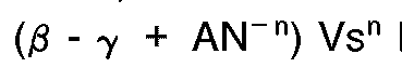
becomes constant while variably controlling the value of γ.
becomes constant while variably controlling the value of γ.
9. A control apparatus according to claim 4, wherein the controlling means (35) controls
the throttle path area AN of the nozzle (4) such that

becomes constant while variably controlling the value of γ.
becomes constant while variably controlling the value of γ.
10. A control apparatus for an injection molding machine which injects a melted resin
within a housing (1) into a cavity (6) of a mold (5) through a nozzle (4) at a housing
end by movement of a screw (2),
comprising
nozzle opening changing means (11,12,13,14) for variably driving the throttle path area AN of the nozzle (4),
screw velocity changing means (22) for controlling the moving velocity Vs of the screw (2),
nozzle opening setting means for setting a target value AN of the nozzle opening inputted to the nozzle opening changing means (11,12,13,14), and
controlling means (55) for receiving the target value AN of the nozzle opening, for calculating the moving velocity Vs of the screw (2) such that Vs/AN becomes constant corresponding to the target value AN, and for outputting the value Vs thus calculated into the screw velocity changing means (22).
comprising
nozzle opening changing means (11,12,13,14) for variably driving the throttle path area AN of the nozzle (4),
screw velocity changing means (22) for controlling the moving velocity Vs of the screw (2),
nozzle opening setting means for setting a target value AN of the nozzle opening inputted to the nozzle opening changing means (11,12,13,14), and
controlling means (55) for receiving the target value AN of the nozzle opening, for calculating the moving velocity Vs of the screw (2) such that Vs/AN becomes constant corresponding to the target value AN, and for outputting the value Vs thus calculated into the screw velocity changing means (22).
1. Steuervorrichtung für eine Spritzgußmaschine, die ein in einem Gehäuse (1) befindliches
geschmolzenes Harz mittels Bewegung einer Schraube (2) durch eine an einem Gehäuseende
angeordnete Düse (4) in einen Hohlraum (6) einer Form (5) spritzt,
mit
einer Düsenöffnungsveränderungseinrichtung (11, 12,13,14) zum variablen Steuern der Drosselwegfläche AN der Düse (4),
einer Schraubengeschwindigkeitsveränderungseinrichtung (22) zum Steuern der Bewegungsgeschwindigkeit Vs der Schraube (2), und
einer die Bewegungsgeschwindigkeit Vs der Schraube (2) empfangenden Steuereinrichtung (35) zum Errechnen der Drosselwegfläche AN der Düse (4), derart, daß Vs/AN entsprechend der Geschwindigkeit Vs konstant wird, und zum Ausgeben des so errechneten Wertes AN an die Düsenöffnungsveränderungseinrichtung (11,12,13,14).
mit
einer Düsenöffnungsveränderungseinrichtung (11, 12,13,14) zum variablen Steuern der Drosselwegfläche AN der Düse (4),
einer Schraubengeschwindigkeitsveränderungseinrichtung (22) zum Steuern der Bewegungsgeschwindigkeit Vs der Schraube (2), und
einer die Bewegungsgeschwindigkeit Vs der Schraube (2) empfangenden Steuereinrichtung (35) zum Errechnen der Drosselwegfläche AN der Düse (4), derart, daß Vs/AN entsprechend der Geschwindigkeit Vs konstant wird, und zum Ausgeben des so errechneten Wertes AN an die Düsenöffnungsveränderungseinrichtung (11,12,13,14).
2. Steuervorrichtung nach Anspruch 1, bei der die Form (5) einen Einguß (16), einen Angußkanal
(17) und einen Anguß (18) aufweist, und bei der die Steuereinrichtung (35) die Drosselwegfläche
AN der Düse (4) derart errechnet, daß
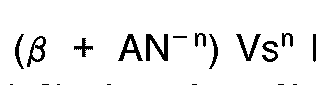
konstant wird, wobei β die Gesamtsumme der Querschnittsbereiche in dem Einguß (16), dem Angußkanal (17) und dem Anguß (18) ist und n eine durch das Harz bestimmte Konstante ist, und den so errechneten Wert AN an die Düsenöffnungsveränderungseinrichtung (11,12,13,14) ausgibt.
konstant wird, wobei β die Gesamtsumme der Querschnittsbereiche in dem Einguß (16), dem Angußkanal (17) und dem Anguß (18) ist und n eine durch das Harz bestimmte Konstante ist, und den so errechneten Wert AN an die Düsenöffnungsveränderungseinrichtung (11,12,13,14) ausgibt.
3. Steuervorrichtung nach Anspruch 1, bei der die Form (5) einen Einguß (16), einen Angußkanal
(17) und einen Anguß (18) aufweist, und bei der die Steuereinrichtung (35) die Drosselwegfläche
AN der Düse (4) derart errechnet, daß

konstant wird, wobei β die Gesamtsumme der Querschnittsbereiche in dem Einguß (16), dem Angußkanal (17) und dem Anguß (18) ist, γ der durch das Abkühlen der Formtemperatur verursachte Abfall der Harztemperatur ist, und n eine durch das Harz bestimmte Konstante ist, und den so errechneten Wert AN an die Düsenöffnungsveränderungseinrichtung (11,12,13,14) ausgibt.
konstant wird, wobei β die Gesamtsumme der Querschnittsbereiche in dem Einguß (16), dem Angußkanal (17) und dem Anguß (18) ist, γ der durch das Abkühlen der Formtemperatur verursachte Abfall der Harztemperatur ist, und n eine durch das Harz bestimmte Konstante ist, und den so errechneten Wert AN an die Düsenöffnungsveränderungseinrichtung (11,12,13,14) ausgibt.
4. Steuervorrichtung nach Anspruch 1, bei der die Steuereinrichtung (35) die Drosselwegfläche
AN der Düse (4) derart errechnet, daß
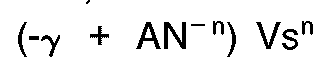
konstant wird, wobei γ der durch das Abkühlen der Formtemperatur verursachte Abfall der Harztemperatur ist, und n eine durch das Harz bestimmte Konstante ist, und den so errechneten Wert AN an die Düsenöffnungsveränderungseinrichtung (11,12,13,14) ausgibt.
konstant wird, wobei γ der durch das Abkühlen der Formtemperatur verursachte Abfall der Harztemperatur ist, und n eine durch das Harz bestimmte Konstante ist, und den so errechneten Wert AN an die Düsenöffnungsveränderungseinrichtung (11,12,13,14) ausgibt.
5. Steuervorrichtung nach Anspruch 1, bei der die in die Steuereinrichtung (35) eingegebene
Bewegungsgeschwindigkeit Vs der Schraube (2) ein in die Schraubengeschwindigkeitsveränderungseinrichtung
(22) eingegebener Zielwert ist.
6. Steuervorrichtung nach Anspruch 1, bei der die in die Steuereinrichtung (35) eingegebene
Bewegungsgeschwindigkeit Vs der Schraube (2) der ermittelte Wert der Bewegungsgeschwindigkeit
der Schraube (2) ist.
7. Steuervorrichtung nach Anspruch 1, bei der während eines Einspritzvorgangs die Schraubengeschwindigkeitsveränderungseinrichtung
(22) die Bewegungsgeschwindigkeit der Schraube (2) in mehrere unterschiedliche Geschwindigkeiten
ändert.
8. Steuervorrichtung nach Anspruch 3, bei der die Steuereinrichtung (35) die Drosselwegfläche
AN der Düse (4) derart steuert, daß

konstant wird, während sie den Wert von γ veränderlich steuert.
konstant wird, während sie den Wert von γ veränderlich steuert.
9. Steuervorrichtung nach Anspruch 4, bei der die Steuereinrichtung (35) die Drosselwegfläche
AN der Düse (4) derart steuert, daß
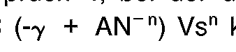
konstant wird, während sie den Wert von γ veränderlich steuert.
konstant wird, während sie den Wert von γ veränderlich steuert.
10. Steuervorrichtung für eine Spritzgußmaschine, die ein in einem Gehäuse (1) befindliches
geschmolzenes Harz mittels Bewegung einer Schraube (2) durch eine an einem Gehäuseende
angeordnete Düse (4) in einen Hohlraum (6) einer Form (5) spritzt,
mit
einer Düsenöffnungsveränderungseinrichtung (11, 12,13,14) zum variablen Steuern der Drosselwegfläche AN der Düse (4),
einer Schraubengeschwindigkeitsveränderungseinrichtung (22) zum Steuern der Bewegungsgeschwindigkeit Vs der Schraube (2),
einer Düsenöffnungseinstelleinrichtung (22) zum Einstellen eines Zielwertes AN der Düsenöffnung, der in die Düsenöffnungsveränderungseinrichtung (11,12,13,14) eingegeben wird, und
einer den Zielwert AN der Düsenöffnung empfangenden Steuereinrichtung (55) zum Errechnen der Bewegungsgeschwindigkeit Vs der Schraube (2) derart, daß Vs/AN entsprechend dem Zielwert AN konstant wird, und zum Ausgeben des so errechneten Wertes Vs an die Schraubengeschwindigkeitsveränderungseinrichtung (22).
mit
einer Düsenöffnungsveränderungseinrichtung (11, 12,13,14) zum variablen Steuern der Drosselwegfläche AN der Düse (4),
einer Schraubengeschwindigkeitsveränderungseinrichtung (22) zum Steuern der Bewegungsgeschwindigkeit Vs der Schraube (2),
einer Düsenöffnungseinstelleinrichtung (22) zum Einstellen eines Zielwertes AN der Düsenöffnung, der in die Düsenöffnungsveränderungseinrichtung (11,12,13,14) eingegeben wird, und
einer den Zielwert AN der Düsenöffnung empfangenden Steuereinrichtung (55) zum Errechnen der Bewegungsgeschwindigkeit Vs der Schraube (2) derart, daß Vs/AN entsprechend dem Zielwert AN konstant wird, und zum Ausgeben des so errechneten Wertes Vs an die Schraubengeschwindigkeitsveränderungseinrichtung (22).
1. Une unité de commande pour machines de moulage à injection qui injectent une résine
fondue, se trouvant à l'intérieur d'un boîtier (1), dans une cavité (6) d'un moule
(5), à travers une buse (4) à une extrémité du boîtier, par le déplacement d'une vis
(2),
comprenant
un moyen de modification (11, 12, 13, 14) de l'ouverture de buse, destiné à régler, de manière variable, la section d'obturation du papillon AN de la buse (4),
un moyen de modification (22) de la vitesse de la vis, destiné à régler la vitesse de déplacement Vs de la vis (2), et
un moyen de commande (35), destiné à recevoir la vitesse de déplacement Vs de la vis (2), afin de calculer la section d'obturation du papillon AN de la buse (4) de manière que Vs/AN devient constant en fonction de la vitesse Vs, et à sortir la valeur AN ainsi calculée vers le moyen de modification (11, 12, 13, 14) de l'ouverture de buse.
comprenant
un moyen de modification (11, 12, 13, 14) de l'ouverture de buse, destiné à régler, de manière variable, la section d'obturation du papillon AN de la buse (4),
un moyen de modification (22) de la vitesse de la vis, destiné à régler la vitesse de déplacement Vs de la vis (2), et
un moyen de commande (35), destiné à recevoir la vitesse de déplacement Vs de la vis (2), afin de calculer la section d'obturation du papillon AN de la buse (4) de manière que Vs/AN devient constant en fonction de la vitesse Vs, et à sortir la valeur AN ainsi calculée vers le moyen de modification (11, 12, 13, 14) de l'ouverture de buse.
2. Une unité de commande suivant la revendication 1, dans laquelle le moule (5) comporte
un canal d'injection (16), un canal de distribution (17) et une entrée (18), et dans
laquelle le moyen de commande (35) calcule la section d'obturation du papillon AN
de la buse (4) de manière que
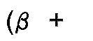

devient constant, où β est la somme totale des surfaces des sections du canal d'injection (16), du canal de distribution (17) et de l'entrée (18), et n est une constante fonction de la résine, et sort la valeur AN ainsi calculée vers le moyen de modification (11, 12, 13, 14) de l'ouverture de buse.
devient constant, où β est la somme totale des surfaces des sections du canal d'injection (16), du canal de distribution (17) et de l'entrée (18), et n est une constante fonction de la résine, et sort la valeur AN ainsi calculée vers le moyen de modification (11, 12, 13, 14) de l'ouverture de buse.
3. Une unité de commande suivant la revendication 1, dans laquelle le moule (5) comporte
un canal d'injection (16), un canal de distribution (17) et une entrée (18), et dans
laquelle le moyen de commande (35) calcule la section d'obturation du papillon AN
de la buse (4) de manière que
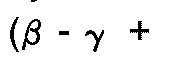
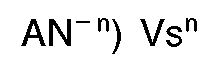
devient constant, où β est la somme totale des surfaces des sections du canal d'injection (16), du canal de distribution (17) et de l'entrée (18), γ est la chute de température de la résine due au refroidissement de la température du moule, et n est une constante fonction de la résine, et sort la valeur AN ainsi calculée vers le moyen de modification (11, 12, 13, 14) de l'ouverture de buse.
devient constant, où β est la somme totale des surfaces des sections du canal d'injection (16), du canal de distribution (17) et de l'entrée (18), γ est la chute de température de la résine due au refroidissement de la température du moule, et n est une constante fonction de la résine, et sort la valeur AN ainsi calculée vers le moyen de modification (11, 12, 13, 14) de l'ouverture de buse.
4. Une unité de commande suivant la revendication 1, dans laquelle le moyen de commande
(35) calcule la section d'obturation du papillon AN de la buse (4) de manière que

devient constant, où γ est la chute de température de la résine due au refroidissement de la température du moule, et n est une constante fonction de la résine, et sort la valeur AN ainsi calculée vers le moyen de modification (11, 12, 13, 14) de l'ouverture de buse.
devient constant, où γ est la chute de température de la résine due au refroidissement de la température du moule, et n est une constante fonction de la résine, et sort la valeur AN ainsi calculée vers le moyen de modification (11, 12, 13, 14) de l'ouverture de buse.
5. Une unité de commande suivant la revendication 1, dans laquelle la vitesse de déplacement
Vs de la vis (2) entrée dans le moyen de commande (35) est une valeur cible entrée
dans le moyen de modification (22) de la vitesse de la vis.
6. Une unité de commande suivant la revendication 1, dans laquelle la vitesse de déplacement
Vs de la vis (2) entrée dans le moyen de commande (35) est la valeur détectée de la
vitesse de déplacement de la vis (2).
7. Une unité de commande suivant la revendication 1, dans laquelle le moyen de modification
(22) de la vitesse de la vis change la vitesse de déplacement de la vis (2) en une
pluralité de vitesses différentes au cours d'un processus d'injection.
8. Une unité de commande suivant la revendication 3, dans laquelle le moyen de commande
(35) règle la section d'obturation du papillon AN de la buse (4) de manière que

devient constant, tout en réglant de manière variable la valeur de γ.
devient constant, tout en réglant de manière variable la valeur de γ.
9. Une unité de commande suivant la revendication 4, dans laquelle le moyen de commande
(35) règle la section d'obturation du papillon AN de la buse (4) de manière que

devient constant, tout en réglant de manière variable la valeur de γ.
devient constant, tout en réglant de manière variable la valeur de γ.
10. Une unité de commande pour machines de moulage à injection qui injectent une résine
fondue, se trouvant à l'intérieur d'un boîtier (1), dans une cavité (6) d'un moule
(5), à travers une buse (4) à une extrémité du boîtier, par le déplacement d'une vis
(2),
comprenant
un moyen de modification (11, 12, 13, 14) de l'ouverture de buse destiné à régler, de manière variable, la section d'obturation du papillon AN de la buse (4),
un moyen de modification (22) de la vitesse de la vis, destiné à régler la vitesse de déplacement Vs de la vis (2),
un moyen de réglage de l'ouverture de buse destiné à régler une valeur cible AN d'une ouverture de tuyère entrée dans le moyen de modification (11, 12, 13, 14) de l'ouverture de buse, et
un moyen de commande (35) destiné à recevoir la vitesse cible AN de l'ouverture de buse, afin de calculer la vitesse de déplacement Vs de la vis (2) de manière que Vs/AN devient constant en fonction de la valeur cible AN et de sortir la valeur Vs ainsi calculée vers le moyen de modification (22) de la vitesse de la vis.
comprenant
un moyen de modification (11, 12, 13, 14) de l'ouverture de buse destiné à régler, de manière variable, la section d'obturation du papillon AN de la buse (4),
un moyen de modification (22) de la vitesse de la vis, destiné à régler la vitesse de déplacement Vs de la vis (2),
un moyen de réglage de l'ouverture de buse destiné à régler une valeur cible AN d'une ouverture de tuyère entrée dans le moyen de modification (11, 12, 13, 14) de l'ouverture de buse, et
un moyen de commande (35) destiné à recevoir la vitesse cible AN de l'ouverture de buse, afin de calculer la vitesse de déplacement Vs de la vis (2) de manière que Vs/AN devient constant en fonction de la valeur cible AN et de sortir la valeur Vs ainsi calculée vers le moyen de modification (22) de la vitesse de la vis.