|
(11) | EP 0 434 673 B1 |

| (12) | EUROPEAN PATENT SPECIFICATION |
|
|
| (54) |
KNOCK CONTROL IN INTERNAL COMBUSTION ENGINES KLOPFREGELVORRICHTUNG BEI INNEREN BRENNKRAFTMASCHINEN REGULATION DE LA DETONATION DANS DES MOTEURS A COMBUSTION INTERNE |
|
|
||||||||||||||||||||||||
| Note: Within nine months from the publication of the mention of the grant of the European patent, any person may give notice to the European Patent Office of opposition to the European patent granted. Notice of opposition shall be filed in a written reasoned statement. It shall not be deemed to have been filed until the opposition fee has been paid. (Art. 99(1) European Patent Convention). |
[0001] The present invention relates to a knock control system for internal combustion engines. The invention is particularly applicable to spark ignition engines having electronic ignition.
[0002] It is now well known in computer or microprocessor controlled electronic ignition systems to store characteristic data for use in controlling operation of the engine. This may include an ignition base map which optimises the value of ignition angle and dwell period for various operating conditions of the engine. The map stores optimised values for possible combinations of engine speed and engine load which can be modified to compensate for variations in engine temperature for example. The characteristic data is usually derived empirically, supplied by the manufacturer of the engine, and is obtained by running the engine under experimental conditions on a test stand.
[0003] In use, and as the engine wears, components age or are changed, valves and their adjustment change, the fuel quality changes and differs from that under which the tests were made and as a result of these changes the stored characteristics may no longer fit the engine and are less than ideally suited to its control.
[0004] Air pressure, ambient humidity and the like can also change the operation of an engine and affect the suitability of the stored characteristics.
[0005] Therefore the stored characteristics alone are not sufficient to control the operation of the engine. In particular if the ignition angle is not optimised for existing operating conditions, combustion knocking can occur. Combustion knocking can damage an internal combustion engine and should be eliminated if possible. Therefore electronic ignition systems generally include a knock control system. Knocking can be eliminated by retarding the ignition angle but this can have an adverse effect on exhaust emissions and possibly fuel consumption. The ignition should ideally be retarded by the minimum amount sufficient to ensure that knocking does not occur, i.e. the engine should operate close to the knock limit. In practice knocking is detected by a sensor which detects engine vibrations and the knock intensity is determined from the sensor signals. In fact knocking is not eliminated entirely but rather an acceptable intensity band is defined within which the engine should be operated.
[0006] Thus, in an electronic ignition system with knock control, when the engine is at a particular operating point the electronic control unit (ECU) signals the ignition to be retarded in response to detection of knocking of unacceptable intensity. If, after retardation, unacceptable knocking is still detected the ignition will be retarded further and so on until the knocking is within the acceptable intensity band. When the operation of the engine is moved to another operating point a new value for the ignition angle will be taken from the ignition map and this new value will be modified by the knock control system if necessary. If the detected knock intensity is below the acceptable intensity band the ignition timing may be brought forward by the knock control system until the knock intensity is within that band. This is known as closed-loop knock control.
[0007] A disadvantage with ordinary closed-loop knock control is that when the engine returns to an operating point at which knocking was previously occurring the knock control system has to repeat the process of modifying the ignition angle. Therefore, more recent knock control systems have a "learning" function. With "learning" knock control, as well as the base ignition map, a second "learning" map is stored which contains data for modifying the data in the base ignition map. The data in the learning map is accumulated during running of the engine. Thus, for example, if knocking is detected at a particular operating point, so that the ignition angle from the base map is modified by the closed loop knock control system, a difference value for the ignition angle is stored in the learning map so that when the engine returns to the same operating point the modified value for the ignition angle is used automatically, as derived from the base map together with the learning map, and it is not normally necessary for the closed loop knock control system to further modify the ignition angle. Other factors may effect engine knocking such as fuel quality and atmospheric pressure as mentioned above. If there is a large change in, say, atmospheric pressure before the engine returns to a particular operating point, the closed loop knock control may operate to alter the ignition angle derived from the base map and the learning map and the learning map will be updated.
[0008] A knock control system having a learning function is disclosed in US-A-4700677. Such a system is generally called an adaptive system because the stored functional relationships which control ignition timing are adapted for the current operating conditions.
[0009] In known knock control systems having a learning function as described above, the learning map is updated after a predetermined time which may be defined as a particular number of combustion cycles. This predetermined time must be sufficiently large to establish normal running conditions, i.e. free from transients. On the other hand it must not be too large since otherwise the overall response of the engine to changes in condition will be too slow. The time,which will hereinafter be referred to as the "observation time", is a fixed parameter of the learning algorithm. As a result, the learning algorithm is not able to adapt itself to various operating conditions of the engine resulting from changes in the manner in which the car is being driven. For example, one driver may drive the car very differently from another but known systems cannot be adapted to account for this. Also, the same driver may drive very differently on a motorway from the way he drives through a town. If a driver is particularly erratic, the engine may not remain at operating conditions sufficiently long for the learning map to be updated. The efficiency of the learning process is dependent on the driver, which is clearly undesirable.
[0010] It is an object of the present invention to provide a knock control system which automatically adjusts its learning algorithm to the mode of driving.
[0011] The present invention provides a method of controlling the operation of an internal combustion engine using: memory means storing suitable values of an operating parameter for use at various sets of operating conditions of the engine; a knock detector; and means for adjusting said operating parameter in response to signals from the knock detector; the method comprising: operating the engine using the stored values of said operating parameter from the memory means at each set of operating conditions of the engine; detecting knocking using said knock detector, and adjusting the operating parameter in response to signals from the knock detector; characterised by calculating the length of time for which each set of operating conditions is maintained averaging the amount of adjustment of the operating parameter over said calculated time period and altering the stored parameter values in said memory means by an amount corresponding to the average amount of adjustment or a fraction of said average amount depending on the value of said length of time.
[0012] Let us suppose for example that the adjusting means, which will usually be in the form of a controller, indicates that the ignition angle should be changed by an amount ϑ°. If the operating conditions have been maintained for a sufficiently long time it can be assumed that this indication is good and the value in the memory for these particular operating conditions can be changed by the amount ϑ° . However, if the operating conditions have only been maintained for a short time it may be that this indication has resulted from transient knocking, for example. If the value was changed by the amount ϑ° and the indication did result from transient knocking, the overall result of such a system would be large fluctuations in the stored values in the memory which would adversely affect the running of the engine. According to the invention the memory value is updated by a fraction of ϑ° which depends on the actual time for which the conditions were maintained. The method ensures that the memory is updated even when the operating conditions are changed very quickly by changing the stored values by smaller increments for shorter calculated times. At the same time large fluctuations resulting from transient conditions are avoided.
[0013] An embodiment of the invention will now be described by way of example only and with reference to the accompanying drawing which is a schematic diagram of an internal combustion engine control system according to the invention.
[0014] Numeral 1 in the diagram indicates an engine, which in this example is an Otto-type internal combustion engine of an automotive vehicle. The system for controlling the engine includes controller 2 and memories 3, 4 and 5. Various functions which are carried out by the system and which will be described in more detail below are indicated by numerals 6 to 10. In practice the system will be implemented using an on-board computer or microprocessor in the vehicle.
[0015] Memory 3 is preferably a read-only memory (ROM) which stores basic functional characteristics of the engine. Such data may be supplied by the engine manufacturer. Amongst other things the memory 3 stores the base map referred to above giving optimum ignition angle values for particular operating conditions in terms of engine speed (n) and engine load. The engine will be provided with transducers, not shown, for measuring the rotational speed of the engine and the load. The amount of the load may be ascertained from the inlet manifold pressure (Ps). The transducers will supply signals to the computer which will look up the appropriate value of ignition angle αzv. This value along with modifying data to be described below will be used to control the operation of the engine until the values of engine speed and load are changed and a new value for αzv is supplied.
[0016] The engine is provided with a knock sensor 11 which provides signals over a knock sensing line 12. The knock sensor may be responsive to vibrations of the engine which occur under knocking conditions. Circuitry is provided for analysing signals from the knock sensor 11, indicated generally at 6. Recognition of knocking is well known in the art and will not be discussed further herein.
[0017] If a knocking condition is detected the controller delivers output signals via line 13 to the engine to cause the ignition to be retarded by a certain increment, e.g. 1o angle of rotation. This value is indicated as Δαzs. If knocking is still detected the controller will cause the engine to be retarded further and further (i.e. Δαzs is increased) until the knocking condition is no longer present. When the operating condition is changed the computer will supply a new value for the ignition angle and the process is repeated. The actual ignition angle is indicated as Xz in the diagram.
[0018] If it is detected that the engine is operating under non-knocking conditions and should be brought closer to the knock limit, i.e. the knock intensity is below the acceptable band mentioned above, the ignition is brought forward by increments until the engine is operating at the knock limit. The way in which this is carried out will be described in more detail below.
[0019] Numeral 4 in the diagram indicates a second memory which is preferably a random access memory (RAM) and which stores, usually along with other data, the learning map referred to above. The learning map contains data for modifying information in the base map of memory 3 to compensate, for example, for changes in fuel quality, changes in ambient humidity and atmospheric pressure and changes in the components of the engine affecting its operation. For every value of ignition angle αzv contained in the base map in memory 3 there may be a value ΔαZL in memory 4 representing a change in ignition angle. During operation of the engine both memories 3 and 4 are addressed and the actual value of ignition angle used for operating the engine is αzv - ΔαZL.
[0020] Signals representing changes in ignition angle ΔαZS, supplied by the controller 2 are supplied to the RAM 4 along data line 14. The signals from the controller which represent values of ΔαZS are used to update the information in the learning map. The manner in which data in the learning nap is accumulated and updated is controlled by the algorithms indicated at 9 and 10. The algorithms utilise information from a second random access memory 5 which will be described in more detail below.
[0021] While the engine is being driven its operating conditions will vary and different values from the base map in memory 3 will be used to control the ignition angle. Thus, for example, when the engine speed is between x and x+Δx revolutions per minute and the inletmanifold pressure is between y and y+Δy N/m² the ignition angle Z₁ will be looked up from memory 3 and when the engine speed or load moves out of this range a new ignition angle Z₂ will be looked up from memory 3. The knock control system of the present invention calculates how long each set of operating conditions is maintained before the conditions move to a new point on the base map in memory 3 and a new ignition angle is looked up. This is indicated by numeral 7 in the diagram. Thus, for each combination of engine speed and load through which the engine is driven, a time period will be calculated which is hereinafter referred to as the "staying time". The staying times are stored in a memory 5 which is preferably another random access memory. Thus, memory 5 contains another map which stores a staying time ts for combinations of speed and load corresponding to the speed and load points on the maps in the memories 3 and 4. The "staying times" may be calculated as actual times but they are preferably calculated as numbers of combustion cycles, for reasons which will be explained below.
[0022] Each staying time which is calculated is preferably averaged with any staying time for the same operating point already stored in memory 5. This is indicated at 8 in the diagram. The new average staying time is written over the existing average staying time in memory 5.
[0023] The manner in which the memory 4 is updated for retarding the ignition is controlled by the algorithm indicated at 10 in the drawings. Suppose that the engine operates at between x and x+Δx revs engine speed with a pressure between y and y+Δy N/m² for a staying time of T₁. During this time knocking occurs and the controller retards the ignition by several increments until no knocking occurs with a change in ignition angle of Δαl.
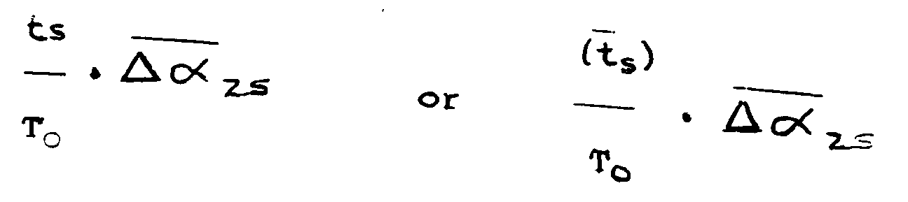
[0024] Assuming no transient knocking was occurring, the value Δαl would be written into the learning map for retarding the ignition angle when the engine returned to the same operating conditions. However, as mentioned above transient conditions have to be taken into account. In the present method, the signals representing values ΔαZS supplied from controller 2 are averaged over the time T₁ before being supplied to the learning map. The average staying time ts for the operating conditions present during the time T₁ is compared with a preset observation time To. If ts is greater than or equal to To the average value of ΔαZS supplied by controller 2 during the time T₁ is added to the value ΔαZL in the learning map of memory 4 to provide a new value of ΔαZL. If however ts is less than To because the operating conditions have only been maintained for a short time, the value of ΔαZL is only changed by a fraction of the calculated average value of ΔαZS. This fraction is preferably equal to (ts ÷ To).
[0025] Thus, if the manner of driving is such that the operating conditions are changed slowly the values of ts will be large and the learning map will be changed by the full calculated average values of ignition angle from the controller ΔαZS. However, if the operating conditions are only maintained for short periods of time the learning map is altered but by a smaller amount which is dependent on the actual staying times.
[0026] If the values in the learning map were incremented by the full calculated average values of ΔαZS for very small staying times, and if transient knocking occurred during those staying times this would result in large fluctuations in the values stored in the learning map and unsatisfactory operation of the engine. The method described above ensures that the learning map is updated even if the manner of driving is such that the staying times are smaller, whilst avoiding such large fluctuations.
[0027] It is preferred to average the values of ΔαZS supplied from the controller and to update memory 4 on the basis of average values because the output from the controller is not steady and they may have a sawtooth shape even in the steady state after knocking has been eliminated. The averaging of the staying times may be necessary in order to avoid too wide a dynamic range in the learning algorithm (for example unnecessary frequent reorientation in the learning process).
[0028] The manner in which the memory 4 is updated for bringing the ignition forward is controlled by a forward learning algorithm indicated at 9. The forward learning algorithm analyses signals from the knock recognition circuit 6 indicating that no knocking is occurring. When such conditions exist it is generally desirable to bring the ignition forward so that it is close to the knock limit so as to optimise emissions and fuel consumption whilst ensuring that knocking does not occur. Thus, when "no-knocking" signals are received from the knock recognition circuit for a particular set of operating conditions, the stored value of ignition angle should be altered so that the ignition timing is brought forward. In the preferred embodiment of the present invention the values of ΔαZL in the memory 4 are automatically incremented when no knocking occurs. Again the amount by which ΔαZL is changed depends on the average waiting time for the particular operating conditions stored in the memory 5. The controller 2 does not participate in the advancement of the ingnition. Also, there is no fixed waiting time. The amount by which ΔαZL is changed simply depends on the value of ts stored in memory 5.
[0029] Alternatively the algorithm 9 can correspond to the algorithm 10. In this case signals from the controller would be analysed to provide an average value of ΔαZS from the controller (in this case this would be a positive angle whereas for algorithm 10 it would be a negative angle). The amount of change of the value in memory 4 could depend on ts from the memory 5 as well as the average ΔαZS from controller 2 exactly as before.
[0030] Preferably the adaptive data stored in memory 4 is stored in an electronically erasable programmable read-only memory (EE PROM) or a non-volatile random access memory (NVRAM) so that the data will be stored if the engine is switched off. When the ignition is switched on at some time later the new values of ignition angle from memories 3 and 4 will be used to operate the engine but they will be modified to take account of changed conditions of the engine such as engine temperature.
[0031] Memory 5 is preferably erased when the engine is switched off so that a new set of data is accumulated in it, for example when a new driver takes over.
[0032] In a practical system a separate controller 2 will be provided for each cylinder of the engine being controlled since each cylinder will have its own individual characteristics. Also, the memories 3 and 4 will store operating data for each individual cylinder i.e. for a four cylinder engine four maps, similar to that shown, will be stored in memory 3.
[0033] As mentioned above the "staying times" may be calculated as actual times or they may be calculated as numbers of combustion cycles. The latter is preferred because the system is then adaptive for engine speed. In this case the observation time To will be defined as a predetermined number of combustion cycles.
[0034] An additional advantage of the present invention is that it is less dependant on fixed parameters for the operation of the learning alogorithm. For example, in the known knock control systems with a learning function the "observation time" would have to be determined for each particular engine. In the present invention, the observation time To is less critical to the operation of the method and does not have to be precisely calculated.
1. A method of controlling the operation of an internal combustion engine using:
memory means (3, 4) storing suitable values of an operating parameter(αZ) for use at various sets of operating conditions (n, Ps) of the engine (1);
a knock detector (11); and
means (2) for adjusting said operating parameter(αZ) in response to signals from the knock detector;
the method comprising:
operating the engine using the stored values of said operating parameter from the memory means at each set of operating conditions of the engine,
detecting knocking using said knock detector, and
adjusting the operating parameter (αZ) in response to signals from the knock detector (11);
characterised by calculating the length of time (ts) or which each set of operating conditions is maintained,averaging the amount of adjustment of the operating parameter (ΔαZS) over said calculated time period (ts) and altering the stored parameter values in said memory means by an amount equal to the average amount of adjustment(ΔαZS) or a fraction of said average amount depending on the value of said length of time (ts).
memory means (3, 4) storing suitable values of an operating parameter(αZ) for use at various sets of operating conditions (n, Ps) of the engine (1);
a knock detector (11); and
means (2) for adjusting said operating parameter(αZ) in response to signals from the knock detector;
the method comprising:
operating the engine using the stored values of said operating parameter from the memory means at each set of operating conditions of the engine,
detecting knocking using said knock detector, and
adjusting the operating parameter (αZ) in response to signals from the knock detector (11);
characterised by calculating the length of time (ts) or which each set of operating conditions is maintained,averaging the amount of adjustment of the operating parameter (ΔαZS) over said calculated time period (ts) and altering the stored parameter values in said memory means by an amount equal to the average amount of adjustment(ΔαZS) or a fraction of said average amount depending on the value of said length of time (ts).
2. A method as claimed in claim 1 in which said operating parameter is the ignition angle
(αZ).
3. A method as claimed in claim 1 or 2 in which the operating conditions are defined
as particular combinations of engine speed (n) and engine load (Ps).
4. A method as claimed in claim 1, 2 or 3 in which the memory means includes a first
memory (3) which stores basic functional data relating to the engine including values
of said operating conditions; and a second memory (4)) storing data for modifying
the data in the first memory (3); and in which only the stored parameter values in
said second memory (4) are altered.
5. A method as claimed in claim 4 in which the second memory (4) is an EEPROM or NVRAM
which retains its current data when the engine is switched off.
6. A method as claimed in any preceding claim in which the calculated time periods (ts) for each operating condition are averaged during operation of the engine and the
stored parameter values are adjusted in dependence on the average calculated time
periods (ts).
7. A method as claimed in claim 6 in which the calculated average values are stored in
a further memory (5) and updated each time the engine returns to the respective operating
conditions.
8. A method as claimed in any preceding claim in which the calculated length of time
(ts) or the average calculated length of time (ts) for each set of operating conditions is compared to a predetermined time period
(To), and if the calculated time or the average calculated time exceeds To the stored parameter in said memory means is adjusted by the average amount of adjustment
(ΔαZS) over the time (ts).
9. A method as claimed in any preceding claim in which the calculated length of time
(ts) or the average calculated length of time (ts) for each set of operating conditions is compared to a predetermined time period
(To), and if calculated time (ts) or the average calculated time (ts) is Less than To, the stored parameter is adjusted by an amount equal to
10. A method as claimed in any preceding claim in which the signals from the knock detector
are signals indicating that knocking is occurring.
11. A method as claimed in claim 10 in which the knock detector is used to provide signals
indicative of the intensity of knocking and the operating parameter for each set of
operating conditions is adjusted when the knock intensity is below a predetermined
value.
12. A method as claimed in claim 11 in which the operating parameter is adjusted when
the knock intensity is below a predetermined value by an amount depending on said
calculated length of time (ts).
1. Eine Methode zur Steuerung des Betriebs eines Motors mit innerer Verbrennung, der
folgendes verwendet:
Speichereinrichtungen (3, 4) zur Speicherung geeigneter Werte eines Betriebsparameters (αz) für die Verwendung mit mehreren Sätzen von Betriebsbedingungen (n, Ps) des Motors (1);
einen Klopfsensor (11); und
Einrichtungen (2) zum Einstellen dieses Betriebsparameters (αz) in Abhängigkeit von Signalen des Klopfsensors;
eine Methode, die umfaßt:
den Betrieb des Motors mit den gespeicherten Werten des erwähnten Betriebsparameters aus den Speichereinrichtungen für jeden Satz von Betriebsbedingungen des Motors,
die Erfassung des Klopfens mit dem erwähnten Klopfsensor, und
das Korrigieren des Betriebsparameters (αz) in Abhängigkeit von Signalen des Klopfsensors (11);
dadurch gekennzeichnet, daß die Länge der Zeit (ts) berechnet wird, für die jeder Satz von Betriebsbedingungen aufrechterhalten wird, wobei der Durchschnitt des Korrekturbetrags des Betriebsparameters (ΔαZS) während dieser berechneten Zeitspanne (ts) ermittelt wird, und daß die gespeicherten Parameterwerte in diesen Speichereinrichtungen durch einen Betrag geändert werden, der je nach dem Wert dieser Zeitspanne (ts) gleich dem Durchschnittsbetrag der Korrektur (ΔαZS) oder einem Bruchteil dieses Durchschnittsbetrags ist.
Speichereinrichtungen (3, 4) zur Speicherung geeigneter Werte eines Betriebsparameters (αz) für die Verwendung mit mehreren Sätzen von Betriebsbedingungen (n, Ps) des Motors (1);
einen Klopfsensor (11); und
Einrichtungen (2) zum Einstellen dieses Betriebsparameters (αz) in Abhängigkeit von Signalen des Klopfsensors;
eine Methode, die umfaßt:
den Betrieb des Motors mit den gespeicherten Werten des erwähnten Betriebsparameters aus den Speichereinrichtungen für jeden Satz von Betriebsbedingungen des Motors,
die Erfassung des Klopfens mit dem erwähnten Klopfsensor, und
das Korrigieren des Betriebsparameters (αz) in Abhängigkeit von Signalen des Klopfsensors (11);
dadurch gekennzeichnet, daß die Länge der Zeit (ts) berechnet wird, für die jeder Satz von Betriebsbedingungen aufrechterhalten wird, wobei der Durchschnitt des Korrekturbetrags des Betriebsparameters (ΔαZS) während dieser berechneten Zeitspanne (ts) ermittelt wird, und daß die gespeicherten Parameterwerte in diesen Speichereinrichtungen durch einen Betrag geändert werden, der je nach dem Wert dieser Zeitspanne (ts) gleich dem Durchschnittsbetrag der Korrektur (ΔαZS) oder einem Bruchteil dieses Durchschnittsbetrags ist.
2. Eine Methode nach Anspruch 1, dadurch gekennzeichnet, daß es sich bei dem Betriebsparameter
um den Zündverstellwinkel (αz) handelt.
3. Eine Methode nach Anspruch 1 oder 2, dadurch gekennzeichnet, daß die Betriebsbedingungen
als bestimmte Kombinationen von Motordrehzahl (n) und Motorlast (Ps) definiert werden.
4. Eine Methode nach Anspruch 1, 2 oder 3, dadurch gekennzeichnet, daß die Speichereinrichtungen
einen ersten Speicher (3), der die grundlegenden Funktionsdaten des Motors einschließlich
der Werte der erwähnten Betriebsbedingungen erfaßt, sowie einen zweiten Speicher (4)
umfassen, der Daten zum Modifizieren der Daten im ersten Speicher (3) enthält, und
daß nur die gespeicherten Parameterwerte in diesem zweiten Speicher (4) verändert
werden.
5. Eine Methode nach Anspruch 4, dadurch gekennzeichnet, daß es sich bei dem zweiten
Speicher (4) um einen EEPROM- oder NVRAM-Speicher handelt, der seine aktuellen Daten
beibehält, wenn der Motor ausgeschaltet wird.
6. Eine Methode nach einem der vorausgehenden Ansprüche, dadurch gekennzeichnet, daß
der Durchschnitt der berechneten Zeitspannen (ts) für jede Betriebsbedingung während des Betriebs des Motors berechnet wird und daß
die gespeicherten Parameterwerte in Abhängigkeit von den als Durchschnitt berechneten
Zeitspannen (ts) korrigiert werden.
7. Eine Methode nach Anspruch 6, dadurch gekennzeichnet, daß die berechneten Durchschnittswerte
in einem weiteren Speicher (5) gespeichert und immer dann aktualisiert werden, wenn
der Motor zu den jeweiligen Betriebsbedingungen zurückkehrt.
8. Eine Methode nach einem der vorausgehenden Ansprüche, dadurch gekennzeichnet, daß
die berechnete Zeitspanne (ts) oder die als Durchschnitt berechnete Zeitspanne (ts) für jeden Satz von Betriebsbedingungen mit einer vorbestimmten Zeitspanne (To) verglichen wird, und daß, wenn die berechnete Zeitspanne oder die als Durchschnitt
berechnete Zeitspanne To übersteigt, der gespeicherte Parameter in dieser Speichereinrichtung durch den durchschnittlichen
Korrekturbetrag (ΔαZS) für die Zeit (ts) korrigiert wird.
9. Eine Methode nach einem der vorausgehenden Ansprüche, dadurch gekennzeichnet, daß
die berechnete Zeitspanne (ts) oder die als Durchschnitt berechnete Zeitspanne (ts) für jeden Satz von Betriebsbedingungen mit einer vorbestimmten Zeitspanne (To) verglichen wird, und daß, wenn die berechnete Zeitspanne (ts) oder die als Durchschnitt berechnete Zeitspanne (ts) weniger als To beträgt, der gespeicherte Parameter durch einen Wert korrigiert wird, der gleich
oder

ist.
ist.
10. Eine Methode nach einem der vorausgehenden Ansprüche, dadurch gekennzeichnet, daß
es sich bei den Signalen des Klopfsensors um Signale handelt, die anzeigen, daß ein
Klopfen vorliegt.
11. Eine Methode nach Anspruch 10, dadurch gekennzeichnet, daß der Klopfsensor verwendet
wird, um Signale zu liefern, die die Intensität des Klopfens anzeigen, und daß der
Betriebsparameter für jeden Satz von Betriebsbedingungen korrigiert wird, wenn die
Klopfintensität unter einem vorbestimmten Wert liegt.
12. Eine Methode nach Anspruch 11, dadurch gekennzeichnet, daß bei einer unter einem vorbestimmten
Wert liegenden Klopfintensität der Betriebsparameter um einen Betrag korrigiert wird,
der von der berechneten Zeitspanne (ts) abhängt.
1. Procédé de régulation du fonctionnement d'un moteur à combustion interne utilisant
:
des moyens de mémoire (3, 4) stockant des valeurs convenables d'un paramètre de commande (αZ) destiné à être utilisé dans divers ensembles de conditions de fonctionnement (n, PS) du moteur (1) ;
un détecteur de détonation (11) ; et
des moyens (2) de réglage du paramètre de commande (αZ) en réponse aux signaux provenant du détecteur de détonation ;
le procédé comprenant :
la commande du moteur en utilisant les valeurs stockées du paramètre de commande provenant des moyens de mémoire pour chaque ensemble de conditions de fonctionnement du moteur,
la détection de la détonation en utilisant le détecteur de détonation, et
le réglage du paramètre de commande (αZ) en réponse aux signaux provenant du détecteur de détonation (11) ;
caractérisé en ce qu'il consiste à calculer la durée (ts) pendant laquelle chaque ensemble de conditions de fonctionnement est maintenue, à former la moyenne des valeurs de réglage du paramètre de commande (ΔαZS) pendant la période de temps calculée (ts), et à modifier les valeurs du paramètre stockées dans les moyens de mémoire par une quantité égale à la valeur moyenne de réglage (ΔαZS) ou à une fraction de cette valeur moyenne dépendant de la valeur de la durée (ts).
des moyens de mémoire (3, 4) stockant des valeurs convenables d'un paramètre de commande (αZ) destiné à être utilisé dans divers ensembles de conditions de fonctionnement (n, PS) du moteur (1) ;
un détecteur de détonation (11) ; et
des moyens (2) de réglage du paramètre de commande (αZ) en réponse aux signaux provenant du détecteur de détonation ;
le procédé comprenant :
la commande du moteur en utilisant les valeurs stockées du paramètre de commande provenant des moyens de mémoire pour chaque ensemble de conditions de fonctionnement du moteur,
la détection de la détonation en utilisant le détecteur de détonation, et
le réglage du paramètre de commande (αZ) en réponse aux signaux provenant du détecteur de détonation (11) ;
caractérisé en ce qu'il consiste à calculer la durée (ts) pendant laquelle chaque ensemble de conditions de fonctionnement est maintenue, à former la moyenne des valeurs de réglage du paramètre de commande (ΔαZS) pendant la période de temps calculée (ts), et à modifier les valeurs du paramètre stockées dans les moyens de mémoire par une quantité égale à la valeur moyenne de réglage (ΔαZS) ou à une fraction de cette valeur moyenne dépendant de la valeur de la durée (ts).
2. Procédé selon la revendication 1, caractérisé en ce que le paramètre de commande est
l'angle d'allumage (αZ).
3. Procédé selon l'une quelconque des revendications 1 et 2, caractérisé en ce que les
conditions de fonctionnement sont définies comme des combinaisons particulières de
la vitesse (n) du moteur et de la charge (PS) du moteur.
4. Procédé selon l'une quelconque des revendications 1 à 3, caractérisé en ce que les
moyens de mémoire comprennent une première mémoire (3) qui stocke les données de fonctionnement
de base concernant le moteur, ces données comprenant les valeurs des conditions de
fonctionnement ; et une seconde mémoire (4) stockant des données destinées à modifier
les données contenues dans la première mémoire (3) ; et en ce que seules les valeurs
du paramètre stockées dans la seconde mémoire (4) sont modifiées.
5. Procédé selon la revendication 4, caractérisé en ce que la seconde mémoire (4) est
une EE PROM ou une NVRAM qui conserve ses données courantes lorsque le moteur est
coupé.
6. Procédé selon l'une quelconque des revendications précédentes, caractérisé en ce qu'on
forme la moyenne des périodes de temps calculées (ts) pour chaque condition de commande pendant le fonctionnement du moteur, et en ce
que les valeurs stockées du paramètre sont réglées en fonction de la moyenne des périodes
de temps calculées (ts).
7. Procédé selon la revendication 6, caractérisé en ce que les valeurs moyennes calculées
sont stockées dans une autre mémoire (5) et mises à jour à chaque fois que le moteur
revient à ses conditions de fonctionnement respectives.
8. Procédé selon l'une quelconque des revendications précédentes, caractérisé en ce que
la longueur de temps calculée (ts) ou la valeur moyenne de la longueur de temps calculée (ts) pour chaque ensemble de conditions de fonctionnement, est comparée à une période
de temps prédéterminée (To), et en ce que, si le temps calculé ou la moyenne du temps calculé dépasse To, le paramètre stocké dans les moyens de mémoire est réglé par la valeur moyenne de
réglage (ΔαZS) pendant la durée (ts).
9. Procédé selon l'une quelconque des revendications précédentes, caractérisé en ce que
la longueur de temps calculée (ts) ou la moyenne de la longueur de temps calculée (ts) pour chaque ensemble de conditions de fonctionnement, est comparée à une période
de temps prédéterminée (To), et en ce que, si le temps calculé (ts) ou la moyenne du temps calculé (ts) est inférieur à To, le paramètre stocké est réglé par une quantité égale à
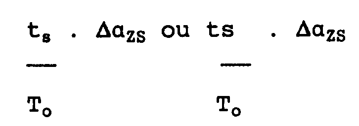
10. Procédé selon l'une quelconque des revendications précédentes, caractérisé en ce que
les signaux provenant du détecteur de détonation sont des signaux indiquant que la
détonation se produit.
11. Procédé selon la revendication 10, caractérisé en ce que le détecteur de détonation
est utilisé pour fournir des signaux indiquant l'intensité de la détonation, et en
ce que le paramètre de commande pour chaque ensemble de conditions de fonctionnement
est réglé lorsque l'intensité de la détonation est inférieure à une valeur prédéterminée.
12. Procédé selon la revendication 11, caractérisé en ce que le paramètre de commande
est réglé lorsque l'intensité de la détonation est inférieure à une valeur prédéterminée
d'une quantité qui dépend de la longueur de temps calculée (ts).