| (19) |
 |
|
(11) |
EP 0 448 863 B1 |
| (12) |
EUROPEAN PATENT SPECIFICATION |
| (45) |
Mention of the grant of the patent: |
|
04.01.1995 Bulletin 1995/01 |
| (22) |
Date of filing: 04.10.1990 |
|
|
| (54) |
Motor cover assembly and method
Motor-Deckeleinheit und Verfahren
Ensemble moteur-couvercle et méthode
|
| (84) |
Designated Contracting States: |
|
BE DE ES FR GB IT |
| (30) |
Priority: |
26.03.1990 US 498699
|
| (43) |
Date of publication of application: |
|
02.10.1991 Bulletin 1991/40 |
| (73) |
Proprietor: COPELAND CORPORATION |
|
Sidney
Ohio 45365-0669 (US) |
|
| (72) |
Inventor: |
|
- Brown, James Martin
Sidney,
Ohio 45365 (US)
|
| (74) |
Representative: Senior, Alan Murray et al |
|
J.A. KEMP & CO.,
14 South Square,
Gray's Inn
London WC1R 5LX
London WC1R 5LX (GB) |
| (56) |
References cited: :
DE-C- 844 616
US-A- 4 156 821
|
GB-A- 2 006 545
|
|
| |
|
|
|
|
| |
|
| Note: Within nine months from the publication of the mention of the grant of the European
patent, any person may give notice to the European Patent Office of opposition to
the European patent
granted. Notice of opposition shall be filed in a written reasoned statement. It shall
not be deemed to
have been filed until the opposition fee has been paid. (Art. 99(1) European Patent
Convention).
|
Background and Summary of the Invention
[0001] The present invention relates generally to refrigeration compressors and more specifically
to hermetic refrigeration compressors incorporating a motor cover assembly which is
designed to enable the air gap between the motor rotor and stator to be accurately
set prior to securing the cover thereto and a method of assembling such motor covers
and stators.
[0002] Hermetic refrigeration compressors normally incorporate a compressor and associated
driving motor within a hermetically sealed shell. The motor will generally include
a rotor secured to a drive shaft journaled in the compressor housing or other suitable
bearing means and a stator secured to the compressor housing by means of bolts extending
through the stator core. In many designs a motor cover is also provided which is secured
to one end of the stator by the same bolts used to secure the stator to the compressor
housing. In such designs it is very difficult to insure accurate setting of the air
gap between the rotor and stator due to the presence of the motor cover.
[0003] However, the present invention provides an improved motor/motor cover assembly of
the aforementioned general design but which allows the stator to be accurately positioned
and secured to the compressor prior to assembly of the motor cover while still allowing
the stator securing bolts to be used to secure the motor cover to the stator. In the
present design a first pair of stator securing bolts are used to secure the stator
in position once the air gap has been set. Thereafter the cover member is positioned
over the stator and a second pair of stator securing bolts are inserted therethrough
and tightened to thereby secure both the stator to the compressor housing and the
cover to the stator.
[0004] This arrangement thus greatly facilitates the accurate and precise setting of the
air gap yet does not require the separate fabrication and assembly of any additional
components. Thus, cost savings are obtained both in terms of labour and material while
also providing a positive, reliable, securement of the motor cover.
[0005] GB-A-2 006 545 describes a refrigeration compressor providing the basis for the prior
art portion of claim 1 and the method of assembling a refrigeration compressor as
set out in the prior art portion of claim 9. In this prior document, there is proposed
a method of securing a member to the stator, after the stator has been correctly mounted
to the compressor but does it by having a snap-fit fastening to the same retaining
means as secures the stator to the compressor. This means of fastening is completely
unsuitable where the member to be mounted is a cover to the motor which requires a
tight, close, fit as is achieved using the structure as defined in claim 1, where
two separate retaining means are used, one being used initially to adjust the air
gap and properly to position the stator relative to the compressor and the other being
used subsequently, as defined in claim 1, to secure the cover to the stator and at
the same time to provide further securement of the stator to the compressor.
[0006] Additional advantages and features of the present invention will become apparent
from the subsequent description and the appended claims, taken in conjunction with
the accompanying drawings.
Brief Description of the Drawings
[0007]
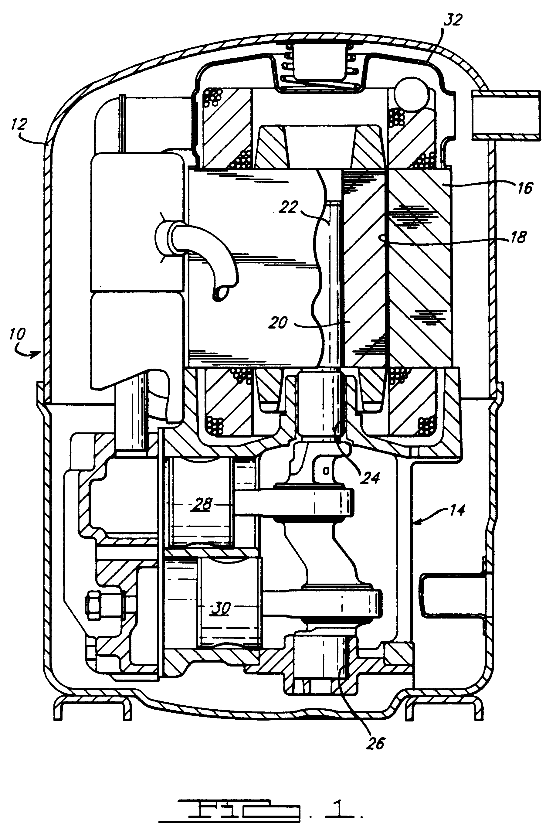
Figure 1 is a section view of hermetic refrigeration compressor in accordance with
the present invention;
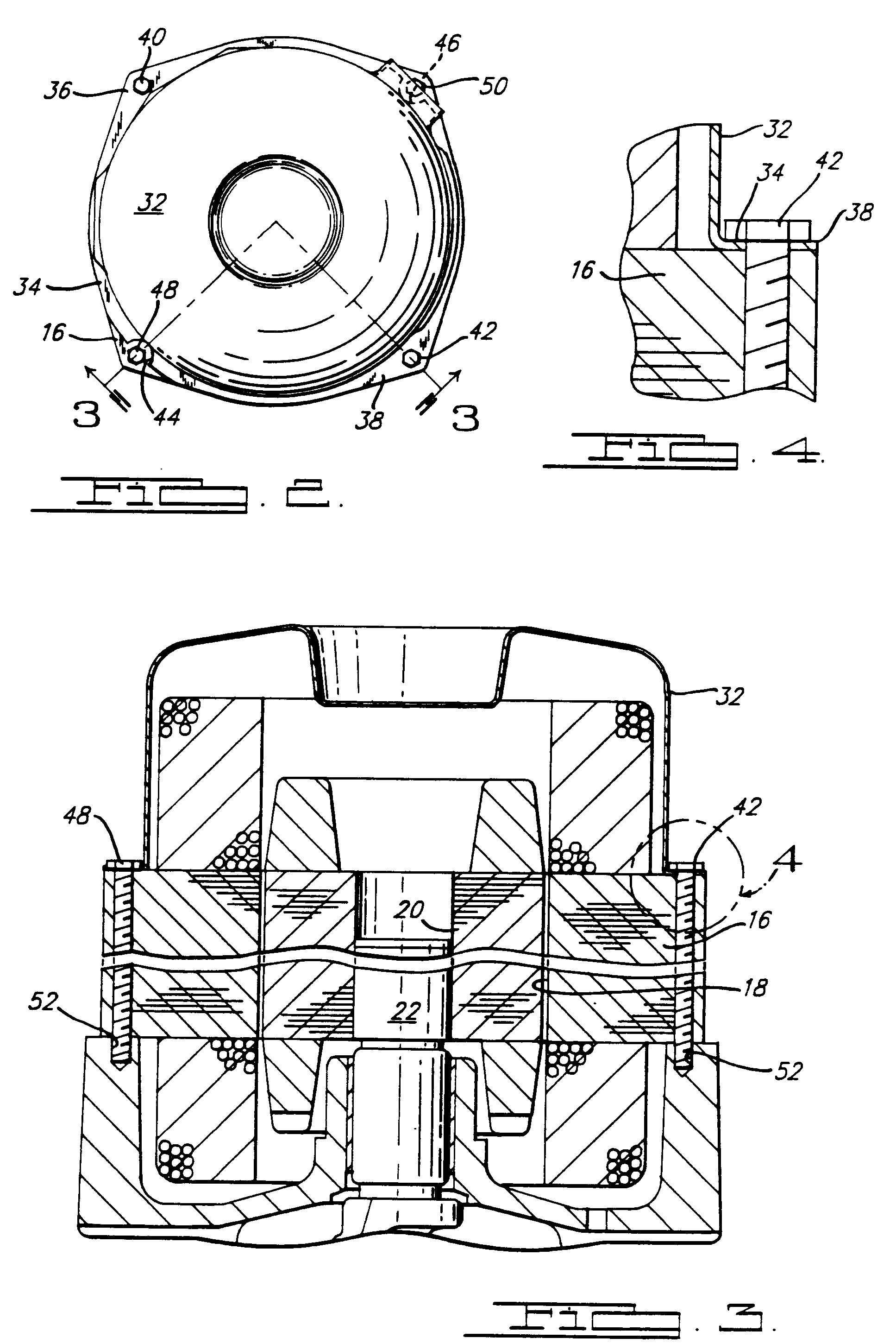
Figure 2 is a top view of the motor cover and associated underlying stator of Figure
1, all in accordance with the present invention;
Figure 3 is a fragmentary section view of the compressor, motor and associated cover
of Figure 1, the section being taken generally along the lines 3-3 of Figure 2; and
Figure 4 is an enlarged fragmentary section view of the area enclosed by circle 4
in Figure 3.
Description of the Preferred Embodiment
[0008] Referring now to the drawings and more specifically to Figure 1, there is shown a
refrigeration compressor generally indicated at 10. Refrigeration compressor 10 is
of the hermetic reciprocating piston type and includes an outer shell 12 having a
compressor housing 14 mounted therein. A driving motor stator 16 has one end supported
by and is secured to compressor housing 14 and includes a cylindrical bore 18 within
which a rotor 20 is supported by means of crankshaft 22. Crankshaft 22 is in turn
rotatably supported by upper and lower bearings 24, 26 provided in compressor housing
14 and serves to reciprocatingly drive pistons 28, 30 provided in compressor housing
14 whereby refrigerant gas may be compressed. A motor cover 32 is also provided being
secured to the end of stator 16 remote from compressor housing 14.
[0009] Referring now to Figures 2 and 3, motor cover 32 is generally cup-shaped and includes
a peripheral flange portion 34 adapted to seat on the upper end of stator 16. Flange
portion 34 includes a pair of diametrically opposed extensions 36 and 38 which serve
to accommodate openings for bolts 40, 42. Also, a pair of diametrically opposed recesses
or cutout portions 44, 46 are provided on flange 34 offset approximately 90° from
respective extensions 36, 38. Recesses 44 and 46 serve to provide a clearance for
respective stator securing bolts 48, 50.
[0010] In assembling, the motor stator 16 is first positioned on the compressor housing
14 and centered so as to provide a uniform air gap between bore 18 and rotor 20. Thereafter
stator securing bolts 48, 50 are tightened thereby locking stator 16 in position so
as to assure the above noted uniform air gap is maintained. Next the motor cover 32
may be positioned in overlying relationship to the upper end of the stator with recess
portions 44 and 46 aligned with the previously tightened stator securing bolts 48,
50. Thereafter, stator securing bolts 40 and 42 are inserted through openings provided
in the extension portions 36, 38 of the motor cover, through the stator 16 and into
threaded engagement with threaded bores 52 provided in compressor housing 14.
[0011] As thus assembled, motor cover 32 is securely retained in assembled relationship
by means of stator securing bolts 40 and 42 while still allowing the stator 16 to
be positively secured in position to afford a uniform air gap prior to assembly of
the motor cover 32. This arrangement allows for a rapid and economical assembly of
the refrigeration compressor.
1. A refrigeration compressor comprising: a compressor means (14,28,30); a motor (16,20)
operative to drive said compressor means (28,30), said motor including a stator (16)
having a cylindrical bore (18) therein and a rotor (20) rotatably supported within
said bore (18); fastening means (48,50) securing said stator (16) to said compressor
means (14), and a member (32) secured to overlie one end of said stator (16);
characterised in that said member is a cover (32) and in that second fastening
means (40,42) are provided that not only secure said cover (32) to said one end of
said stator (16) but also secure said stator (16) to said compressor means (14,28,30),
said first fastening means (48,50) being separate and spaced from said cover (32)
whereby said stator (16) is securable to said compressor means (14) by said first
fastening means (48,50) independently of securement of the cover (32) to the stator
(16).
2. A refrigeration compressor as claimed in claim 1, wherein said cover (32) includes
a peripheral flange (38) adapted to be positioned in opposed relationship to said
one end of said stator (16), said second fastening means (40,42) extending through
openings (44,46) in and engaging said peripheral flange portion (38).
3. A refrigeration compressor as claimed in claim 2, wherein said peripheral flange (38)
has a recess (44,46), with said first fastening means (48,50) being received within
said recess (44,46) so as to be engageable with said stator (16) without engaging
said flange (38).
4. A refrigeration compressor as claimed in any preceding claim, wherein said first and
second fastening means comprise elongated threaded fasteners (48,50,40,42) extending
through bores provided in said stator (16).
5. A refrigeration compressor as claimed in any preceding claim, wherein the compressor
means comprises a compressor housing (14); and a crankshaft (22) rotatably carried
by said compressor housing (14) and secured to said rotor (20); said first fastening
means comprising a first pair of elongated threaded fasteners (48,50) securing one
end of the stator (16) to the compressor housing (14); and said second fastening means
comprising a second pair of elongated threaded fasteners (40,42) securing said motor
cover (32) to said stator (16) and said stator (16) to said compressor housing (14).
6. A refrigeration compressor as claimed in claim 5, wherein said first and second threaded
fasteners (48,50,40,42) are substantially equally spaced.
7. A refrigeration compressor as claimed in claim 5 or 6, wherein said first and second
threaded fasteners (48,50,40,42) extend through bores provided in said stator (16).
8. A refrigeration compressor as claimed in claim 5, 6 or 7, wherein said motor cover
(32) includes a peripheral flange (38) having a pair of spaced recesses (44,46) for
accommodating said first threaded fasteners and a pair of spaced extended portions
(36,38) having openings through which said second threaded fasteners (40,42) extend.
9. A method of assembling a refrigeration compressor of the type having a compressor
housing (14), a motor (20,22) operative to drive said compressor, said motor (20,22)
including a stator (16) secured to said compressor housing (14) and a rotor (20) rotatably
supported within said stator (16) and a motor cover (32) overlying the end of said
stator (16) remote from said compressor housing (14), said method comprising: positioning
said stator (16) with respect to said rotor (20) so as to provide a substantially
uniform air gap therebetween; and securing first fastening means (48,50) to secure
said stator (16) to said compressor housing (14) in said position before assembling
a member (32) to the other end of said stator (16); characterised in that second fastening
means (40,42) are inserted through openings provided in said motor cover (32) and
said stator (16) to engage with said compressor housing (14) and thereby to secure
said motor cover (32) to said stator (16) and further to secure said stator (16) to
said compressor housing (14).
1. Kühlverdichter umfassend: eine Kompressoreinrichtung (14, 28, 30); einen Motor (16,
20) zum Antrieb der Kompressoreinrichtung (28, 30), wobei der Motor einen Ständer
(16) mit einer zylindrischen Bohrung (18) und einen in der Bohrung (18) drehbar gelagerten
Rotor (20) aufweist; Befestigungseinrichtungen (48, 50), die den Ständer (16) an der
Kompressoreinrichtung (14) befestigen, und ein Element (32), das so befestigt ist,
daß es über einem Ende des Ständers (16) liegt;
dadurch gekennzeichnet, daß es sich bei dem Element um eine Abdeckung (32) handelt,
und daß zweite Befestigungseinrichtungen (40, 42) vorgesehen sind, die nicht nur die
Abdekkung (32) an dem einen Ende des Ständers (16) befestigen, sondern auch den Ständer
(16) an der Kompressoreinrichtung (14, 28, 30) befestigen, wobei die ersten Befestigungseinrichtungen
(48, 50) getrennt und im Abstand von der Abdekkung (32) angeordnet sind, so daß der
Ständer (16) an der Kompressoreinrichtung (14) mit Hilfe der ersten Befestigungseinrichtungen
(48, 50) unabhängig von der Befestigung der Abdeckung (32) an dem Ständer (16) befestigt
werden kann.
2. Kühlverdichter nach Anspruch 1, bei dem die Abdekkung (32) einen Umfangsflansch (38)
umfaßt, der gegenüber dem einen Ende des Ständers (16) positioniert werden kann, wobei
die zweiten Befestigungseinrichtungen (40, 42) durch Öffnungen (44, 46) in dem Umfangsflanschabschnitt
(38) ragen und mit diesem in Eingriff stehen.
3. Kühlverdichter nach Anspruch 2, bei dem der Umfangsflansch (38) eine Ausnehmung (44,
46) aufweist, wobei die ersten Befestigungseinrichtungen (48, 50) in der Ausnehmung
(44, 46) aufgenommen sind, so daß sie mit dem Ständer (16) in Eingriff gebracht werden
können, ohne mit dem Flansch (38) in Eingriff zu kommen.
4. Kühlverdichter nach einem der vorhergehenden Ansprüche, wobei die ersten und zweiten
Befestigungseinrichtungen langgestreckte Schraubverbindungselemente (48, 50, 40, 42)
umfassen, die sich durch Bohrungen in dem Ständer (16) erstrecken.
5. Kühlverdichter nach einem der vorhergehenden Ansprüche, bei dem die Kompressoreinrichtung
ein Kompressorgehäuse (14) umfaßt; und eine Kurbelwelle (22), die drehbar in dem Kompressorgehäuse
(14) gelagert ist und an dem Rotor (20) befestigt ist; wobei die ersten Befestigungseinrichtungen
ein erstes Paar langgestreckter Schraubverbindungselemente (48, 50) umfassen, die
ein Ende des Ständers (16) an dem Kompressorgehäuse (14) befestigen; und wobei die
zweiten Befestigungseinrichtungen ein zweites Paar langgestreckter Schraubverbindungselemente
(40, 42) umfassen, die die Motorabdeckung (32) an dem Ständer (16) und den Ständer
(16) an dem Kompressorgehäuse (14) befestigen.
6. Kühlverdichter nach Anspruch 5, bei dem die ersten und zweiten Schraubverbindungselemente
(48, 50, 40, 42) im wesentlichen gleich weit voneinander beabstandet sind.
7. Kühlverdichter nach Anspruch 5 oder 6, bei dem sich die ersten und zweiten Schraubverbindungselemente
(48, 50, 40, 42) durch Bohrungen in dem Ständer (16) erstrecken.
8. Kühlverdichter nach Anspruch 5, 6 oder 7, bei dem die Motorabdeckung (32) einen Umfangsflansch
(38) mit einem Paar voneinander beabstandeter Ausnehmungen (44, 46) zur Aufnahme der
ersten Schraubverbindungselemente aufweist und ein Paar voneinander beabstandeter
herausragender Abschnitte (36, 38) mit Öffnungen, durch die sich die zweiten Schraubverbindungselemente
(40, 42) erstrecken.
9. Verfahren zur Montage eines Kühlverdichters des Typs mit einem Kompressorgehäuse (14),
einem Motor (20, 22) zum Antrieb des Kompressors, wobei der Motor (20, 22) einen Ständer
(16) umfaßt, der an dem Kompressorgehäuse (14) befestigt ist, und einen Rotor (20),
der in dem Ständer (16) drehbar gelagert ist, und eine Motorabdeckung (32), die über
dem von dem Kompressorgehäuse (14) entfernten Ende des Ständers (16) liegt, wobei
das Verfahren folgende Schritte umfaßt: Positionieren des Ständers (16) in bezug auf
den Rotor (20), so daß ein im wesentlichen einheitlicher Luftspalt dazwischen entsteht;
und Anbringen der ersten Befestigungseinrichtungen (48, 50) derart, daß der Ständer
(16) an dem Kompressorgehäuse (14) in dieser Position befestigt wird, bevor ein Element
(32) am anderen Ende des Ständers (16) angebracht wird; dadurch gekennzeichnet, daß
zweite Befestigungseinrichtungen (40, 42) durch Öffnungen in der Motorabdeckung (32)
und dem Ständer (16) eingeführt werden, um mit dem Kompressorgehäuse (14) in Eingriff
zu treten und dadurch die Motorabdeckung (32) an dem Ständer (16) zu befestigen und
des weiteren den Ständer (16) an dem Kompressorgehäuse (14) zu befestigen.
1. Compresseur de réfrigération comprenant: un moyen compresseur (14, 28, 30); un moteur
(16, 20) apte à entraîner ledit moyen compresseur (28, 30), ledit moteur comprenant
un stator (16) comportant un alésage cylindrique (18) à l'intérieur et un rotor (20)
supporté de façon rotative à l'intérieur dudit alésage (18); des moyens de fixation
(48, 50) fixant ledit stator (16) sur ledit moyen compresseur (14) et un organe (32)
fixé de façon à recouvrir une extrémité dudit stator (16);
caractérisé en ce que ledit organe est un couvercle (32) et en ce que des seconds
moyens de fixation (40, 42) sont prévus, qui non seulement fixent ledit couvercle
(32) sur ladite extrémité dudit stator (16), mais fixent également ledit stator (16)
sur ledit moyen compresseur (14, 28, 30), lesdits premiers moyens de fixation (48,
50) étant séparés et espacés dudit couvercle (32), ledit stator (16) pouvant être
fixé audit moyen compresseur (14) par lesdits premiers moyens de fixation (48, 50)
indépendamment de la fixation du couvercle (32) sur le stator (16).
2. Compresseur de réfrigération selon la revendication 1, dans lequel ledit couvercle
(32) comprend une bride périphérique (38) adaptée à être positionnée selon une relation
d'opposition avec ladite extrémité dudit stator (16), lesdits seconds moyens de fixation
(40, 42) s'étendant à travers des ouvertures (44, 46) dans et en engagement avec ladite
portion de bride périphérique (38).
3. Compresseur de réfrigération selon la revendication 2, dans lequel ladite bride périphérique
(38) comprend un évidement (44, 46), lesdits premiers moyens de fixation (48, 50)
étant reçus à l'intérieur dudit évidement (44, 46) de manière à pouvoir être amenés
en engagement avec ledit stator (16) sans venir en engagement avec ladite bride (38).
4. Compresseur de réfrigération selon l'une quelconque des revendications précédentes,
dans lequel lesdits premiers et seconds moyens de fixation comprennent des éléments
de fixation filetés allongés (48, 50, 40, 42) s'étendant à travers des alésages prévus
dans ledit stator (16).
5. Compresseur de réfrigération selon l'une quelconque des revendications précédentes,
dans lequel le moyen compresseur comprend un carter de compresseur (14); et un arbre
manivelle (22) supporté de façon rotative par ledit carter de compresseur (14) et
fixé audit rotor (20); lesdits premiers moyens de fixation comprenant une première
paire d'éléments de fixation filetés et allongés (48, 50) fixant une extrémité du
stator (16) au carter de compresseur (14); et lesdits seconds moyens de fixation comprenant
une seconde paire d'éléments de fixation filetés et allongés (40, 42) fixant ledit
couvercle de moteur (32) audit stator (16) et ledit stator (16) audit carter de compresseur
(14).
6. Compresseur de réfrigération selon la revendication 5, dans lequel lesdits premiers
et seconds éléments de fixation filetés (48, 50, 40, 42) sont espacés sensiblement
de façon égale.
7. Compresseur de réfrigération selon la revendication 5 ou 6, dans lequel lesdits premiers
et seconds éléments de fixation filetés (48, 50, 40, 42) s'étendent à travers des
alésages prévus dans ledit stator (16).
8. Conducteur selon la revendication 5, 6 ou 7, dans lequel ledit couvercle de moteur
(32) comprend une bride périphérique (38) comportant une paire d'évidements espacés
(44, 46) pour recevoir lesdits premiers éléments de fixation filetés et une paire
de portions prolongées et espacées (36, 38) comportant des ouvertures par lesquelles
s'étendent lesdits seconds éléments de fixation filetés (40, 42).
9. Procédé pour assembler un compresseur de réfrigération du type comportant un carter
de compresseur (14), un moteur (20, 22) apte à entraîner ledit compresseur, ledit
moteur (20, 22) comprenant un stator (16) fixé audit carter de compresseur (14) et
un rotor (20) supporté de façon rotative à l'intérieur dudit stator (16) et un couvercle
de moteur (32) recouvrant l'extrémité dudit stator (16) qui est éloignée dudit carter
de compresseur (14), ledit procédé comprenant:
le positionnement dudit stator (16) par rapport à audit rotor (20) de manière à
constituer entre eux un intervalle d'air sensiblement uniforme; et la fixation des
premiers moyens de fixation (48, 50) pour fixer ledit stator (16) sur ledit carter
de compresseur (14) dans ladite position avant l'assemblage d'un élément (32) à l'autre
extrémité dudit stator (16);
caractérisé en ce que lesdits seconds moyens de fixation (40, 42) sont insérés
par des ouvertures prévues dans ledit couvercle de moteur (32) et ledit stator (16)
pour venir en engagement avec ledit carter de compresseur (14) et fixer ainsi ledit
couvercle de moteur (32) sur ledit stator (16) et en outre fixer ledit stator (16)
sur ledit carter de compresseur (14).