| (19) |
 |
|
(11) |
EP 0 459 050 B1 |
| (12) |
EUROPEAN PATENT SPECIFICATION |
| (45) |
Mention of the grant of the patent: |
|
25.08.1993 Bulletin 1993/34 |
| (22) |
Date of filing: 01.06.1990 |
|
| (51) |
International Patent Classification (IPC)5: A47K 10/28 |
|
| (54) |
System for selectively activating dispensers
System zum auswählenden Aktivieren von Spendern
Système pour activer sélectivement des distributeurs
|
| (84) |
Designated Contracting States: |
|
AT BE CH DE DK ES FR GB GR IT LI LU NL SE |
| (43) |
Date of publication of application: |
|
04.12.1991 Bulletin 1991/49 |
| (73) |
Proprietor: STEINER COMPANY, INC. |
|
Chicago
Illinois 60611 (US) |
|
| (72) |
Inventor: |
|
- Steiner, Robert L.
Chicago,
Illinois 60611 (US)
|
| (74) |
Representative: Newby, Martin John et al |
|
JY & GW Johnson,
Kingsbourne House,
229-231 High Holborn
London WC1V 7DP
London WC1V 7DP (GB) |
| (56) |
References cited: :
GB-A- 774 970
NL-A- 8 600 003
|
GB-A- 2 162 151
|
|
| |
|
|
|
|
| |
|
| Note: Within nine months from the publication of the mention of the grant of the European
patent, any person may give notice to the European Patent Office of opposition to
the European patent
granted. Notice of opposition shall be filed in a written reasoned statement. It shall
not be deemed to
have been filed until the opposition fee has been paid. (Art. 99(1) European Patent
Convention).
|
[0001] This invention pertains to a system for automatically enabling selected ones of a
number of dispensers to be operated in a predetermined sequence. While the invention
broadly encompasses the dispensing of any goods much as soap, confectionery, linen
or paper towels or the like, it is intended to be used with linen towel dispensers
of the kind commonly found in washrooms, factories and other commercial locations.
[0002] It is relatively common for a commercial establishment to have more than one dispenser
and since these dispensers are serviced only periodically, uneven usage results in
certain of the dispensers being empty and others of the dispensers being partially
used and still others being hardly used at all. In order to alleviate this uneven
usage, it is proposed to provide a system wherein at least one and maybe more than
one dispensers are made available for use while the other dispensers are.unavailable
for use. Upon the occurrence of an event, which may be the absence or near , absence
of the material in the dispenser, a triggering mechanism causes other dispensers to
become available for use. By this system, it is proposed that.the material to be dispensed,
whether it is linen towels, soap or confectionery will be used in a more orderly and
efficient manner. For soap and towels, this results in easier maintenance and a more
complete use of the material to be dispensed while for confectionery and the like
it results in fresher goods being available since none of the goods will be retained
for prolonged periods of tine, thus becoming stale.
[0003] GB-A-2 162 151 discloses a system for automatically enabling selected ones of a plurality
of dispensers to be operated in a predetermined sequence comprising: a plurality of
dispensers each having storage for a quantity of goods to be dispensed and a mechanism
for dispensing stored goods in repeated dispensing operations, each dispenser having
a storage condition wherein the stored goods are unavailable for use (see flap 3)
and a dispensing condition wherein the stored goods can be dispensed by a user, control
means associated with at least one dispenser, means associated with each dispenser
having a control means for sensing an event and for activating said control means
in response thereto, and actuating means operatively connected to said control means
for changing the dispenser from the storage condition thereof to the dispensing condition
thereof in response to said control means, whereby the stored goods in said dispenser
become available to be dispensed by said dispensing mechanism to a user. The present
invention improves on this arrangement by the features of the characterising clause
of claim 1.
[0004] An example of the invention will now be described with reference to the accompanying
drawings in which:
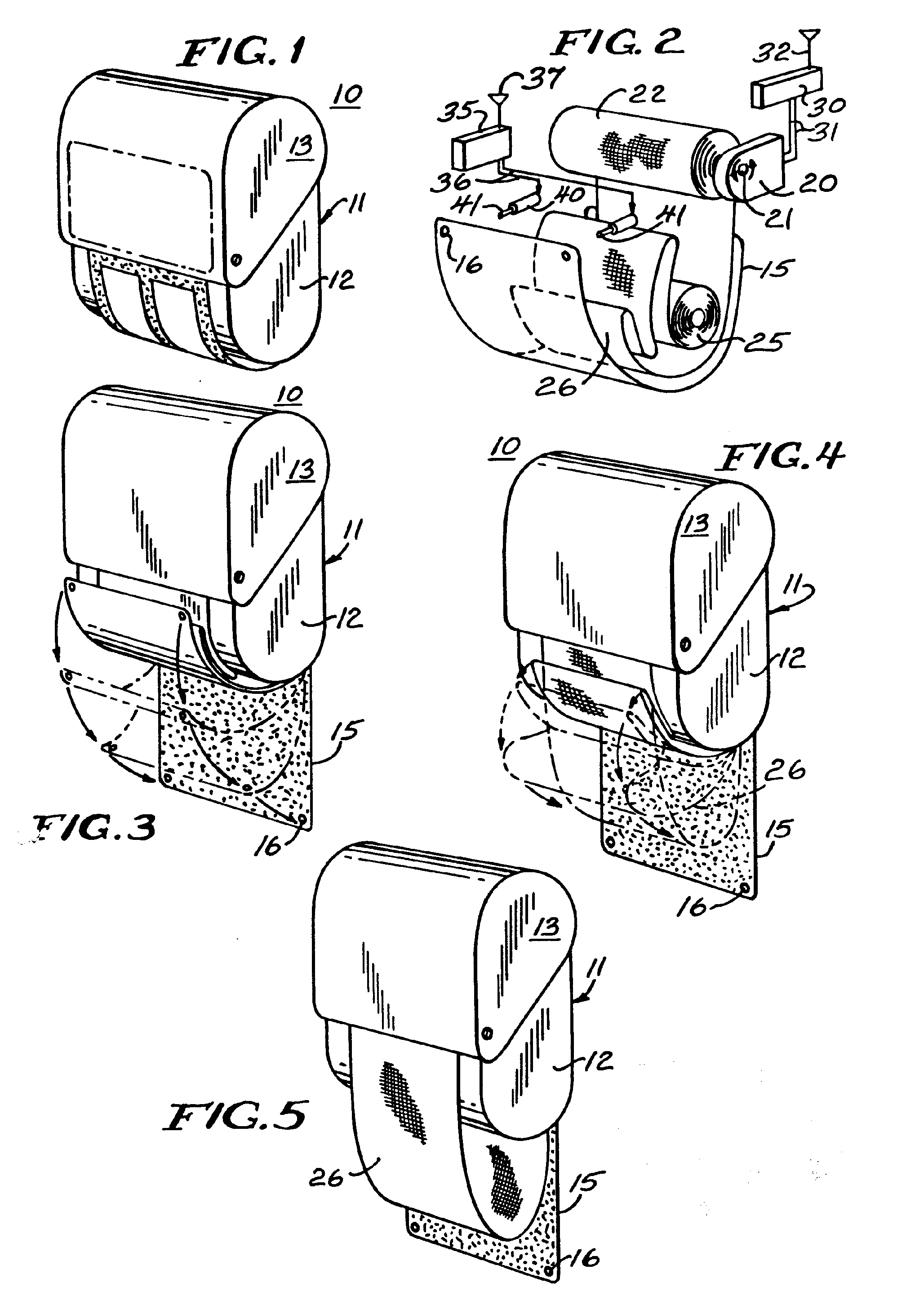
Figure 1 is a perspective view of a towel cabinet in a condition wherein the clean
toweling is unavailable for use;
Figure 2 is an exploded view of the principal components of the towel cabinet of Figure
1 with the housing removed;
Figures 3 to 5 are perspective views like Figure 1 showing the positions of the towel
cabinet as it is transformed from a condition wherein the toweling is unavailable
for use to a condition in which the toweling is available for use; and
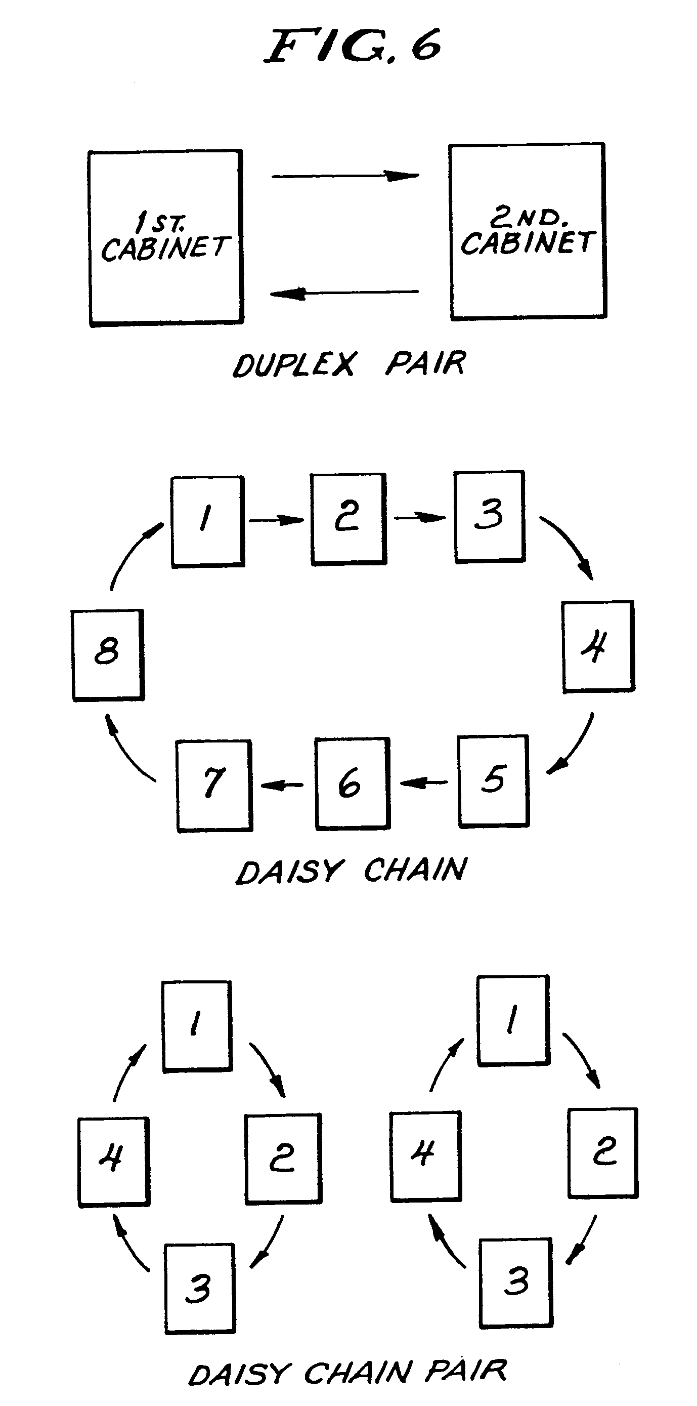
Figure 6 is a schematic representation of several sequential operations for a plurality
of dispensers.
[0005] Referring now to the drawings there is disclosed in Figures 1-5, a representative
dispenser 10 which in the illustration is for clean linen toweling; however, the invention
is not limited to toweling and is applicable to the various items hereinbefore discussed
and to others those skilled in the art will appreciate. The towel dispenser 10 includes
a cabinet 11 having a pair of opposed side panels 12 interconnected by a pivoted cover
13. The cover 13 is shown in the closed position in the drawings but is pivoted to
open to have soiled towelling removed and clean towelling replaced. It is common in
the towel dispensing art to sense an event, such as the absence of towelling or the
lack of tension, and to actuate a device such as a spring in response to the event
to cause something to happen, such as the tail end of a towel roll being taken into
a cabinet, for instance see U.S. patent application filed by Hartman et al., serial
no. 164,456, March 4, 1988 (U.S. patent no.4826262), Steiner et al., U.S. patent no.
3,502,383 issued March 20, 1970, P.W. Jespersen, U.S. patent no. 3,437,388 issued
April 8, 1969 and to E.B. Bahnsen, U.S. patent no. 3,323,848 issued June 6, 1967,
the disclosures of which are incorporated herein by reference. At the bottom of the
present towel cabinet is a flexible shield 15 having a pair of spaced apart apertures
16 at the free end thereof. The flexible shield 15 is fixedly connected to the rear
of the towel cabinet and is flexibly wrapped around the bottom of the towel cabinet
and releasably connected inside the cover 13, as will be explained.
[0006] The towel dispenser 10 further includes a towel take-up mechanism 20 which is well
known in the art having a shaft 21 which is motorized either by electrical means or
by a spring. Around the shaft 21 is stored the used toweling 22, as is well known.
A roll of clean toweling 25 is housed within the cabinet 11 and has a loop 26 which
in use extends downwardly and below the cabinet for ready access by an intended user.
[0007] The towel dispenser 10 has a transmitter 30 connected to the towel take-up mechanism
20 by leads 31 and an antenna 32. A receiver 35 is connected by suitable means 36
to a pair of solenoids 40 each having a retractable pin or piston 41 which is dimensioned
to fit through the adjacent or aligned aperture 16 at the end of the shield 15
[0008] Figure 1 of the drawings shows a towel dispenser 10 in the condition wherein the
fresh toweling 25 is unavailable for use and in that condition the cover 13 is closed,
the shield 15 is snugly wrapped around the exterior loop 26 and traps the loop against
the bottom of the cabinet 11, and the pins or pistons 41 of the solenoids 40 extend
through the associated aperture 16 in the shield 15 to maintain the shield in position.
In addition, in the condition shown in Fig. 1 with the cover 13 in place, the pistons
41 of the solenoids 40 are secure against tampering due to the fact that the pistons
are protected by the cover 13. This is an important feature to prevent unauthorized
dispensing of the toweling 25 from a towel dispenser 10 prior to the sequence hereinafter
described so as to ensure that the users of the toweling use the toweling in the preferred
manner, that is to exhaust the toweling in one cabinet before another cabinet is made
available for use. Representative sequences which may be employed by dispensers of
the present invention, whether towel dispensers, soap dispensers, confectionery dispensers
or the like, are illustrated in Fig. 6 and include an eight dispenser sequence which
is labeled the daisy chain dispenser or two pairs of four dispensers in a grouping
labeled the daisy chain pair. It will occur to those skilled in the art that various
other configurations may be used but these are representative examples of the types
of sequencing which may be advantageous.
[0009] In the daisy chain configuration, when towel dispenser number one has the clean toweling
roll 25 exhausted, a mechanism well known in the art cited hereinbefore but not shown
herein causes activation of the transmitter 30. The transmitter 30 is set to emit
a signal through the antenna 32 when an event such as the absence of clean toweling
25 occurs. This signal from the transmitter 30 is then received by the antenna 37
of the receiver 35 in the cabinet number 2. Such coding is well known in the garage
door opening art as taught by a variety of patents in that field such as the patents
to Collins et al., U.S. Patent 4,377,006, the patent to Willmott U.S. patent no. 4,037,201
and the patent to Goldstein U.S. patent no. 3,445,848, the disclosures of which are
incorporated herein by reference. These patents show that it is well known in the
art to provide digital codes to transmitter- receiver pairs arid that these transmitter-receivers
may utilize signals which are ultrasonic, infrared or RF in nature but in any event
each transmitter provides a coded signal which is capable of being received by only
those receivers which have been set to receive the signal. In this manner the event
which causes the transmitter 30 to emit a signal through antenna 32 can activate only
one or more specific receivers 35 which then in turn, as described, activate the associated
solenoids 40, retracting the pins or pistons 41 thereby permitting the flexible shields
15 to move from the position shown in Fig. 1 to the position shown in Fig. 5 wherein
the toweling loop 26 is available for use. A shield 15 may be made of any synthetic
organic resin or any other pliable material which will not crack or fail with repeated
use. A simple polyethylene shield is entirely satisfactory for the operation of the
present invention but other plastics or other materials may be more desirable either
because of cost or availability. It is intended that alternatives to the simple shield
such as a segmented shield or even a plastic solid non-flexible shield fall within
the purview of the invention.
1. A system for automatically enabling selected ones of a plurality of dispensers (10)
to be operated in a predetermined sequence comprising: a plurality of dispensers each
having storage for a quantity of goods (22) to be dispensed and a mechanism (20) for
dispensing stored goods in repeated dispensing operations, each dispenser having a
storage condition wherein the stored goods are unavailable for use and a dispensing
condition wherein the stored goods can be dispensed by a user, control means (30,
35) associated with at least one dispenser, sensing means associated with each dispenser
having a control means for sensing an event and for activating said control means
in response thereto, and actuating means (40, 41) operatively connected to said control
means for changing the dispenser from the storage condition thereof to the dispensing
condition thereof in response to said control means, whereby the stored goods in said
dispenser become available to be dispensed by said dispensing mechanism to a user,
characterized by said control means being a remote control means comprising a transmitter
(30) associated with at least one dispenser for transmitting a preselected signal,
and a receiver (35) associated with at least one other dispenser for receiving said
preselected signal.
2. A system as claimed in Claim 1 wherein there are two dispensers.
3. A system as claimed in Claim 1 wherein there are more than two dispensers, at least
one of said dispensers having a said transmitter and a said receiver.
4. A system as claimed in any one of Claims 1 to 3 wherein the or each transmitter sends
a signal which activates a respective one receiver only.
5. A system as claimed in any one of Claims 1 to 4 wherein the event sensed is the absence
of goods to be dispensed.
6. A system as claimed in any one of Claims 1 to 5 comprising a plurality of said transmitters
and wherein each transmitter sends a different signal and only one receiver is capable
of receiving each signal.
7. A system as claimed in any one of Claims 1 to 6 wherein the stored goods are toweling.
8. A system as claimed in Claim 7, wherein said dispensers comprise towel cabinets (11)
each containing a supply of clean toweling (25), said mechanism (20) including means
for dispensing clean toweling in metered portions into a loop (26) exterior of the
associated towel cabinet, characterized by said actuating means including a shield
(15) having one end edge thereof fastened to a rear of the cabinet and latch means
(40, 41) detachably connecting the other end of said shield to said cabinet for holding
the exterior loop of clean toweling unavailable for use, said sensing means sensing
the absence of clean toweling and activating the transmitter, said receiver (35) being
connected to said latch means (40, 41) for releasing said shield in response to a
signal from the transmitter associated with another dispenser to make the exterior
loop of clean toweling available for use, the receivers for each of said dispensers
responding to a signal from only the transmitters of selected ones of said dispensers,
whereby a signal from one transmitter causes only selected latch means to operate
to make clean toweling available.
9. A system as claimed in Claim 8 wherein said latch means includes a solenoid (40) having
a pin (41) engaging said shield to hold said shield in position to trap the exterior
loop of toweling between the cabinet and said shield, said solenoid being actuated
to retract said pin to release said shield.
10. A system as claimed in Claim 8 wherein said shield has a pair of apertures (16) near
the other end thereof and said latch means includes a pair of solenoids each having
a pin which when extended fits through one of the apertures, and each cabinet having
a pivotable cabinet cover (13) which fits over the end of the shield having the apertures
so that the cabinet is tamper-proof while the shield is in position to maintain the
clean toweling unavailable for use.
1. System zur selbsttätigen Freigabe von Spendern, die aus einer Anzahl von Spendern
(10) ausgewählt werden und in einer vorbestimmten Reihenfolge betätigt werden sollen,
wobei das System folgendes umfaßt: eine Vielzahl von Spendern mit jeweils einem Speicher
für eine zu spendende Warenmenge (22) und einem Mechanismus (20) zum Spenden von gespeicherten
Waren in wiederholten Spendevorgängen, wobei jeder Spender einen Speicherzustand,
in dem die gespeicherten Waren nicht zum Gebrauch zur Verfügung stehen, und einen
Spendezustand hat, in dem die gespeicherten Waren an einen Benutzer gespendet werden
können, eine mindestens einem Spender zugeordnete Steuervorrichtung (30, 35), jedem
Spender mit einer Steuervorrichtung zugeordnete Erfassungsmittel zur Erfassung eines
Vorkommnisses und zur dementsprechenden Aktivierung jener Steuervorrichtung sowie
eine Betätigungsvorrichtung (40, 41), die mit jener Steuervorrichtung in Wirkverbindung
steht, um den Spender, als Reaktion auf jene Steuervorrichtung, aus seinem Speicherzustand
in seinen Spendezustand zu bringen, wodurch die in jenem Spender gespeicherten Waren
zum Spenden durch jenen Spendermechanismus an einen Benutzer verfügbar werden, dadurch
gekennzeichnet, daß es sich bei jener Steuervorrichtung um eine Fernsteuervorrichtung
handelt, die einen mindestens einem Spender zugeordneten Sender (30) zum Senden eines
vorgewählten Signals und einen mindestens einem anderen Spender zugeordneten Empfänger
(35) zum Empfangen jenes vorgewählten Signals umfaßt.
2. System nach Anspruch 1, bei dem zwei Spender vorliegen.
3. System nach Anspruch 1, bei dem mehr als zwei Spender vorliegen, wobei mindestens
einer jener Spender einen Sender und einen Empfänger aufweist.
4. System nach einem der Ansprüche 1 bis 3, bei dem der oder jeder Sender ein Signal
abgibt, das nur einen jeweiligen Empfänger aktiviert.
5. System nach einem der Ansprüche 1 bis 4, bei dem es sich bei dem erfaßten Vorkommnis
um die Abwesenheit von zu spendenden Waren handelt.
6. System nach einem der Ansprüche 1 bis 5, das eine Vielzahl jener Sender umfaßt und
bei dem jeder Sender ein anderes-Signal sendet und jedes Signal nur von einem Empfänger
empfangen werden kann.
7. System nach einem der Ansprüche 1 bis 6, bei dem es sich bei den gespeicherten Waren
um Handtücher handelt.
8. System nach Anspruch 7, bei dem jene Spender Handtuchschränkchen (11) umfassen, die
jeweils einen sauberen Handtuchvorrat (25) enthalten, wobei jener Mechanismus (20)
eine Vorrichtung zum Spenden von sauberem Handtuch in dosierten Abschnitten in die
sich außerhalb des zugeordneten Handtuchschränkchens befindliche Schlaufe (26) umfaßt,
dadurch gekennzeichnet, daß jene Betätigungsvorrichtung einen Schild (15), dessen
eine Endkante an einer Rückseite des Schränkchens befestigt ist, und eine Riegelvorrichtung
(40, 41) umfaßt, die das andere Ende jenes Schilds lösbar mit jenem Schränkchen verbindet,
so daß die saubere Handtuchaußenschlaufe nicht für den Gebrauch zur Verfügung steht,
wobei jene Erfassungsvorrichtung die Abwesenheit von sauberem Handtuch erfaßt und
den Sender aktiviert, jener Empfänger (35) mit jener Riegelvorrichtung (40, 41) verbunden
ist, damit jener Schild als Reaktion auf ein Signal von dem einem anderen Spender
zugeordneten Sender freigegeben wird, so daß die saubere Handtuchaußenschlaufe zum
Gebrauch zur Verfügung gestellt wird, und wobei die Empfänger für jeden jener Spender
nur auf ein Signal von den Sendern ausgewählter Spender reagieren und ein Signal von
einem Sender nur ausgewählte Riegelvorrichtungen dazu veranlaßt, sauberes Handtuch
zur Verfügung zu stellen.
9. System nach Anspruch 8, bei dem jene Riegelvorrichtung einen Elektromagnet (40) mit
einem Stift (41) umfaßt, der in den Schild eingreift, so daß dieser in Stellung gehalten
wird und die Handtuchaußenschlaufe zwischen sich und jenem Schränkchen einklemmt,
wobei jener Elektromagnet betätigt wird, woraufhin er jenen Stift zurückzieht und
so jenen Schild freigibt.
10. System nach Anspruch 8, bei dem jener Schild in der nähe seines anderen Endes ein
Paar Öffnungen (16) aufweist, jene Riegelvorrichtung ein Paar Elektromagneten umfaßt,
die jeweils einen Stift aufweisen, der ausgefahren durch eine der Öffnungen paßt,
und jedes Schränkchen eine schwenkbare Schränkchenhaube (13) aufweist, die über das
Schildende mit den Öffnungen paßt, so daß das Schränkchen sicher vor Manipulation
ist, während sich der Schild in Stellung befindet und das saubere Handtuch so hält,
daß es nicht zum Gebrauch zur Verfügung steht.
1. Système permettant l'emploi automatique d'un nombre sélectionné d'une pluralité de
distributeurs (10) dans un ordre prédéterminé, comportant : une pluralité de distributeurs
ayant chacun un stock d'une quantité de produits (22) à distribuer et un mécanisme
(20) de distribution des produits stockés selon des opérations de distribution répétées,
chaque distributeur ayant un état de stockage dans lequel les produits stockés ne
sont pas disponibles pour l'utilisation et un état de distribution dans lequel les
produits stockés peuvent être distribués à un utilisateur, un moyen de commande (30,
35) associé à au moins un distributeur, un moyen de détection associé à chaque distributeur
ayant un moyen de commande, pour détecter un évènement et pour activer ledit moyen
de commande en réponse à cet évènement, et un moyen d'activation (40, 41) relié en
fonctionnement audit moyen de commande pour faire passer le distributeur de son état
de stockage à son état de distribution en réponse audit moyen de commande, les produits
stockés dans ledit distributeur pouvant alors être distribués à un utilisateur par
ledit mécanisme de distribution, caractérisé en ce que ledit moyen de commande est
un moyen de commande à distance comportant un émetteur (30) associé à au moins un
distributeur, pour émettre un signal prédéterminé, et un récepteur (35) associé à
au moins un autre distributeur, pour recevoir ledit signal prédéterminé.
2. Système selon la revendication 1, caractérisé en ce qu'il y a deux distributeurs.
3. Système selon la revendication 1, caractérisé en ce qu'il y a plus de deux distributeurs,
l'un au moins desdits distributeurs ayant un dit émetteur et un dit récepteur.
4. Système selon l'une quelconque des revendications 1 à 3, caractérisé en ce que le
ou chacun des émetteurs envoie un signal qui active seulement un récepteur respectif
unique.
5. Système selon l'une quelconque des revendications 1 à 4, caractérisé en ce que l'évènement
détecté est le manque de produits à distribuer.
6. Système selon l'une quelconque des revendications 1 à 5, caractérisé en ce qu'il comprend
une pluralité desdits émetteurs et en ce que chaque émetteur envoie un signal différent
et qu'uniquement un seul récepteur est capable de recevoir chaque signal.
7. Système selon l'une quelconque des revendications 1 à 6, caractérisé en ce que les
produits stockés sont des essuie-mains.
8. Système selon la revendication 7, caractérisé en ce que lesdits distributeurs comportent
des supports de serviette (11) contenant chacun une quantité d'essuie-mains propre
(25), ledit mécanisme (20) comprenant un moyen de distribution d'essuie-mains propre
en portions mesurées formant une boucle (26) à l'extérieur du support de serviette
associé, caractérisé par ledit moyen d'activation comprenant une plaque de protection
(15) dont une arête d'extrémité est fixée à l'arrière du support et un moyen de verrouillage
(40, 41) reliant de manière détachable l'autre extrémité de ladite plaque de protection
audit support, pour maintenir la boucle extérieure d'essuie-mains propre en position
non disponible pour l'utilisation, ledit moyen de détection détectant le manque d'essuie-mains
propre et activant l'émetteur, ledit récepteur (35) étant relié audit moyen de verrouillage
(40, 41) pour détacher ladite plaque de protection en réponse à un signal de l'émetteur
associé à un autre distributeur pour rendre la boucle extérieure d'essuie-mains propre
disponible pour l'utilisation, les récepteurs de chacun desdits distributeurs répondant
à un signal des émetteurs de seulement un nombre sélectionné desdits distributeurs,
un signal d'un émetteur provoquant ainsi uniquement le mouvement du moyen de verrouillage
sélectionné pour rendre l'essuie-mains propre disponible.
9. Système selon la revendication 8, caractérisé en ce que ledit moyen de verrouillage
comprend un solénoïde (40) ayant une tige (41) s'engageant dans ladite plaque de protection
pour maintenir ladite plaque de protection en position pour coincer la boucle extérieure
d'essuie-mains entre le support et ladite plaque de protection, ledit solénoïde étant
activé pour rétracter ladite tige pour détacher ladite plaque de protection.
10. Système selon la revendication 8, caractérisé en ce que ladite plaque de protection
a une paire de trous (16) près de son autre extrémité et ledit moyen de verrouillage
comprend une paire de solénoïdes ayant chacun une tige qui, dans sa position déployée,
passe dans l'un des trous, et en ce que chaque support a un couvercle (13) de support
pivotant qui s'adapte sur l'extrémité de la plaque de protection présentant les trous,
si bien que le support est protégé contre les manipulations indésirables lorsque la
plaque de protection est en position pour maintenir l'essuie-mains propre non disponible
pour l'utilisation.