|
(11) | EP 0 471 777 B1 |

| (12) | EUROPEAN PATENT SPECIFICATION |
|
|
| (54) |
METHOD FOR LEVELLING THIN STRIPS BY STRETCHING AND BENDING VERFAHREN ZUM RICHTEN VON BÄNDERN DURCH STRECKEN UND BIEGEN PROCEDE POUR DRESSAGE DE FEUILLARDS MINCES PAR ETIRAGE ET CINTRAGE |
|
|
|||||||||||||||||||||||
| Note: Within nine months from the publication of the mention of the grant of the European patent, any person may give notice to the European Patent Office of opposition to the European patent granted. Notice of opposition shall be filed in a written reasoned statement. It shall not be deemed to have been filed until the opposition fee has been paid. (Art. 99(1) European Patent Convention). |
[0001] The present invention concerns a method for levelling strips, the thickness of which is maximum 4 mm, by simultaneous stretching and bending and by help of two levelling rolls only.
BACKGROUND TECHNICS
[0002] Known levelling devices, fig 1, for levelling strips with a small thickness and widths, which can be considerable, is constituted in its central part of a number of zigzag-placed rolls 1 between which the strip 2 is passing and where the surface of the strip 2 is bended in two opposite directions. On the same time the strip 2 is subjected to a stretching in order to move the elastic zone from the centre of the strip at the bending around the levelling rolls 1. The main principle for the levelling of the strip 2 is to bring the material to exceed the yield point 8S across the whole of its cross section in such a way that partly eventual buckles and others are removed, partly the strip leaving the last levelling roll without being bent. Thus the strip is passing the levelling device, fig 1, under a pull effected by a tractive force of the coiling reel 3 and the braking force of the decoiling reel 4. Breaking rolls 5 are arranged on both sides of the levelling roll assembly to compensate changes in the pulling force in the strip 2 at changing outer diameters of the coils at coiling and decoiling. To get a good result a constant pull is required in the strip 2. The stretching force in the strip usually is adjusted in that way that a specific pulling force of 20-40 % of the yield point is reached in the strip. The diameter of the levelling rolls usually is dimensioned according to the unlevelty of the strip before levelling and the thickness of the strip. Normally the roller diameter is about 100 times the thickness t of the strip, but can of course vary within wide limits. A varying roller diameter in the assembly of levelling rolls also can be found. The drawbacks of conventional roller levelling assemblies is among others that these, because of a great number of levelling rolls, are complicated to adjust to get level strips and rather expensive in manufacturing. Also the plastic area of the strip is utilised into a too high degree because of a great number of bendings, which reduces the area of finishing of the material before reaching the breaking point and also hardens considerably because of the cold working.
THE INVENTION
[0003] Surprisingly it has been found that strips can be levelled by only two levelling rolls if, beside: of an appropiate pull in the strip and an appropiate dimension of the diameter of the breaking rolls, the mutual relation between the roller diameters is adjusted. The invention will be described in the claim enclosed, in the closer description below and by help of the enclosed drawings on which figure 1 schematically shows an ordinary straightening machine and figure 2 a tensile test diagram of the actual strip material.
CLOSER DESCRIPTION OF THE INVENTION
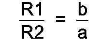
[0004] Initially pieces for tensile test are taken from the strip 2, which is to be levelled, tensile test is made and a diagram for stress and elongation is drawn up in a conventional way with the elongation s as abscissa and the stress a as ordinate, fig 2, (see the Swedish general specification SS 11 21 10). A mainly straight upward slooping line extends from the origin of the coordinates, the elasticity line 7, up to the yield point 8, which after that turns into a more level line, the plasticity line 9. The later line 9 whithout disadvantages can be approximated by a straight line. A radius R1 of the first levelling roll 1 is choosen, which because of earlier experiances from roller levelling devices shall be around or somewhat below 50 times the thickness t of the strip 2. A distance a is pointed out from the origin of coordinates along the abscissa, which distance is equal to the thickness t of the strip divided by the radius R1 of the first roll, and from that point a first parallel line 10 is drawn up against the plasticity line 9, parallel to the elasticity line 7. By that a first surface 11 is constituted in the diagram, fig 2, between the abscissa, the elasticity line 7, the first parallel line 10 and the plasticity line 9. A new second parallel line 12 is drawn to the right of the first surface 11 in that way that a second surface 13 between the abscissa, the first and the second parallel line 10, 12 and the plastcity line 9 becomes equal to the first surface 11. The distance b along the abscissa between the first and the second parallel line 10, 12 is measured. The thickness t of the strip 2 is devided with the later distance b which constitutes the radius R2 of the second levelling roll 1 in the roller levelling device, fig 1. These two rolls are used in a roller levelling device, fig 1, mentioned in the preamble, and the strip 2 is levelled in a usual manner by help of an appropriate pull. By that a level strip 2 is reached.
1. A method for levelling a thin strip (2) by stretching and bending in a roller levelling
device (fig 1) constituted by a braked decoiling reel (4), a stress control device
(5), unpowered rolls (1) and a powered coiling reel (3), characterized in that only
two levelling rolls (1) are used and that the relation between their radiuses, R1
and R2, is determined by making a tensile test according to the Swedish general specification
SS 11 21 10 of the material in the strip (2), a stress elongation diagram (fig 2)
is drawn up with the elongation s as abscissa and the stress a as ordinate, constituted
by an elasticity line (7) starting from the origin of coordinates, followed by a plasticity
line (9), that a distance a is set out from the origin of coordinates along the abscissa,
which is equal to the thickness t of the strip (2) devided by the radius R1 of the
first roll (1), and a first parallel line (10) is drawn parallel to the elasticity
line (7) up to the plasticity line (9), that a second parallel line (12) is drawn
in a corresponding way on a distance b along the abscissa from the first parallel
line (10) in that way that the two surfaces (11, 13) constituted between the abscissa
and the plasticity line (9) are equal and the radius R2 of the second levelling roll
is determined according to the formula
1. Verfahren zum Richten eines dünnen Bandes (2) durch einen Streck- und einen Biegevorgang
in einer Rollen-Richtvorrichtung (Fig. 1), die durch eine gebremste Abwickelrolle
(2), eine Belastungs-Steuervorrichtung (5), nicht-angetriebene Rollen (1) und eine
angetriebene Aufwickelrolle (3) gebildet wird, dadurch
gekennzeichnet,
daß nur zwei Richtrollen (1) benutzt werden und daß die Beziehung zwischen deren Radien, R1 und R2, durch das Durchführen eines Zugversuchs gemäß der schwedischen General-Beschreibung SS 11 21 10 am Material des Bandes (2) durchgeführt wird, daß ein Belastungs-Dehnungsdiagramm (Fig. 2) aufgezeichnet wird, mit der Dehnung als Abszisse und der Belastung a als Ordinate, die durch eine Elastizitätslinie (7) gebildet wird, die vom Nullpunkt der Koordinaten ausgeht und die in eine Plastizitätslinie (9) übergeht,
daß ein Abstand a vom Nullpunkt der Koordinaten längs der Abszisse eingezeichnet wird, der gleich der Dicke t des Bandes (2), geteilt durch den Radius R1 der ersten Rolle (1) ist, und daß eine erste, parallele Linie (10) parallel zur Elastizitätslinie (7) bis zur Elastizitätslinie (9) gezeichnet wird, daß eine zweite, parallele Linie (12) in entsprechender Weise in einem Abstand b längs der Abszisse von der ersten, parallelen Linie so gezogen wird, daß die beiden Flächen (11, 13), die zwischen der Abszisse und der Plastizitätslinie gebildet werden, einander gleich sind, wobei der Radius R2 der zweiten Richtrolle nach der Formel
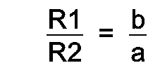
bestimmt wird.
gekennzeichnet,
daß nur zwei Richtrollen (1) benutzt werden und daß die Beziehung zwischen deren Radien, R1 und R2, durch das Durchführen eines Zugversuchs gemäß der schwedischen General-Beschreibung SS 11 21 10 am Material des Bandes (2) durchgeführt wird, daß ein Belastungs-Dehnungsdiagramm (Fig. 2) aufgezeichnet wird, mit der Dehnung als Abszisse und der Belastung a als Ordinate, die durch eine Elastizitätslinie (7) gebildet wird, die vom Nullpunkt der Koordinaten ausgeht und die in eine Plastizitätslinie (9) übergeht,
daß ein Abstand a vom Nullpunkt der Koordinaten längs der Abszisse eingezeichnet wird, der gleich der Dicke t des Bandes (2), geteilt durch den Radius R1 der ersten Rolle (1) ist, und daß eine erste, parallele Linie (10) parallel zur Elastizitätslinie (7) bis zur Elastizitätslinie (9) gezeichnet wird, daß eine zweite, parallele Linie (12) in entsprechender Weise in einem Abstand b längs der Abszisse von der ersten, parallelen Linie so gezogen wird, daß die beiden Flächen (11, 13), die zwischen der Abszisse und der Plastizitätslinie gebildet werden, einander gleich sind, wobei der Radius R2 der zweiten Richtrolle nach der Formel
bestimmt wird.
1. Procédé pour le dressage d'un feuillard mince (2) par étirement et cintrage dans
un dispositif de dressage à rouleaux (figure 1) constitué par une bobine d'enroulement
freinée (4), un dispositif de contrôle des contraintes (5), des rouleaux fous (1)
ainsi qu'une bobine d'enroulement entraînée (3), caractérisé en ce que seulement deux
rouleaux de dressage (1) sont utilisés et que la relation entre leurs rayons, R1 et
R2, est déterminée en effectuant un test d'élasticité en accord avec la spécification
générale en Suède SS 11 21 10 sur les matériaux en bande ou feuillard (2), un diagramme
d'élongation et contraintes (figure 2) étant dessiné avec une élongation ou alongement
s en abscisse et la contrainte 0 en ordonnée, constituée par une ligne élastique (7)
commençant par l'origine des coordonnées, suivie par une ligne de plasticité (9),
une distance a étant définie depuis l'origine des coordonnées le long de l'abscisse,
qui est égale à l'épaisseur t du feuillard (2) divisée par le rayon R1 du premier
rouleau (1), ainsi qu'une première ligne parallèle (10) qui est dessinée parallèlement
à la ligne d'élasticité (7) jusqu'à la ligne de plasticité (9), en ce qu'une seconde
ligne parallèle (12) est dessinée de manière correspondante sur une distance b le
long de l'abscisse depuis la première ligne parallèle (10) de sorte que les deux surfaces
(11, 13) définies entre l'abscisse et la ligne de plasticité (9) soient égales et
que le rayon R2 du second rouleau de dressage soit déterminé en accord avec la formule
suivante :