| (19) |
 |
|
(11) |
EP 0 476 816 B1 |
| (12) |
EUROPEAN PATENT SPECIFICATION |
| (45) |
Mention of the grant of the patent: |
|
06.12.1995 Bulletin 1995/49 |
| (22) |
Date of filing: 01.08.1991 |
|
|
| (54) |
Grid ceiling
Rasterdecke
Plafond en treillis
|
| (84) |
Designated Contracting States: |
|
BE CH DE DK ES FR GB IT LI NL SE |
| (30) |
Priority: |
30.08.1990 US 574676
|
| (43) |
Date of publication of application: |
|
25.03.1992 Bulletin 1992/13 |
| (73) |
Proprietor: HUNTER DOUGLAS INTERNATIONAL NV |
|
Willemstad,
Curaçao (AN) |
|
| (72) |
Inventors: |
|
- Teli, Jonathan P.
Marrietta, GA 30066 (US)
- Heichberger, John J.
Marrietta, GA 30066 (US)
|
| (74) |
Representative: Allen, William Guy Fairfax et al |
|
J.A. KEMP & CO.
14 South Square
Gray's Inn
London WC1R 5LX
London WC1R 5LX (GB) |
| (56) |
References cited: :
EP-A- 0 210 385
GB-A- 2 122 666
US-A- 3 777 432
|
FR-A- 2 523 625
US-A- 2 710 679
US-A- 4 951 443
|
|
| |
|
|
|
|
| |
|
| Note: Within nine months from the publication of the mention of the grant of the European
patent, any person may give notice to the European Patent Office of opposition to
the European patent
granted. Notice of opposition shall be filed in a written reasoned statement. It shall
not be deemed to
have been filed until the opposition fee has been paid. (Art. 99(1) European Patent
Convention).
|
[0001] The present invention relates to grid ceilings. Many different forms of grid ceilings
have been proposed, these usually being designed to cover up services such as water
and gas feed pipes, electric wiring, air conditioning and the like. For example US
Patent Nos. 4658562 and 4665674 show one particular form of ceiling, in which a main
grid is provided and into each of the rectangular openings in this grid is fitted
a grid panel. A somewhat different structure is shown in US Patent No. 4625470 in
which each grid panel is, in effect, formed by two T-shaped members, the stem and
the arms of which are hinged to one other. These grid ceilings are generally satisfactory,
but give a rather limited visual effect. It is an object of the present invention
to provide the facility for giving a greater variety of visual effect.
[0002] Document EP-A-0210385, which represents the closest state of the art, discloses a
grid ceiling which corresponds to the preamble of claim 1. The problem of the invention
is solved by the combination of features of claim 1.
[0003] With such a structure one can readily modify the format of the second smaller grid
element which can be inserted in all or in some of the second openings in a variety
of different arrangements to give a totally different visual effect.
[0004] The first grid element comprises a plurality of first elongate members angled with
respect to one another effective to define said at least one second opening, whereby
said at least one second opening is of polygonal shape. The second grid element may
comprise a plurality of second elongate grid members angled with respect to one another,
the second grid members being shorter in length than the relevant parallelly extending
first grid members. In this way one can have progressively smaller grid elements.
[0005] Desirably the first grid elements are mounted at a level different from the level
of the first and second support members and alternative or additional, the second
grid elements are mounted at a level different from the first and second support members
and indeed may be at a level different from the first grid elements.
[0006] A third opening is defined in the, or each second grid element and a light fitting
or a third grid element is advantageously mounted in the third opening. Additional
grid elements can continue to be mounted in this way. If the grid elements are mounted
at different levels, as suggested above, one can produce, in effect, a pyramidal shape
in each opening in the support members.
[0007] In order that the present invention may more readily be understood, the following
description is given, merely by way of example, reference being made to the accompanying
drawings in which:-
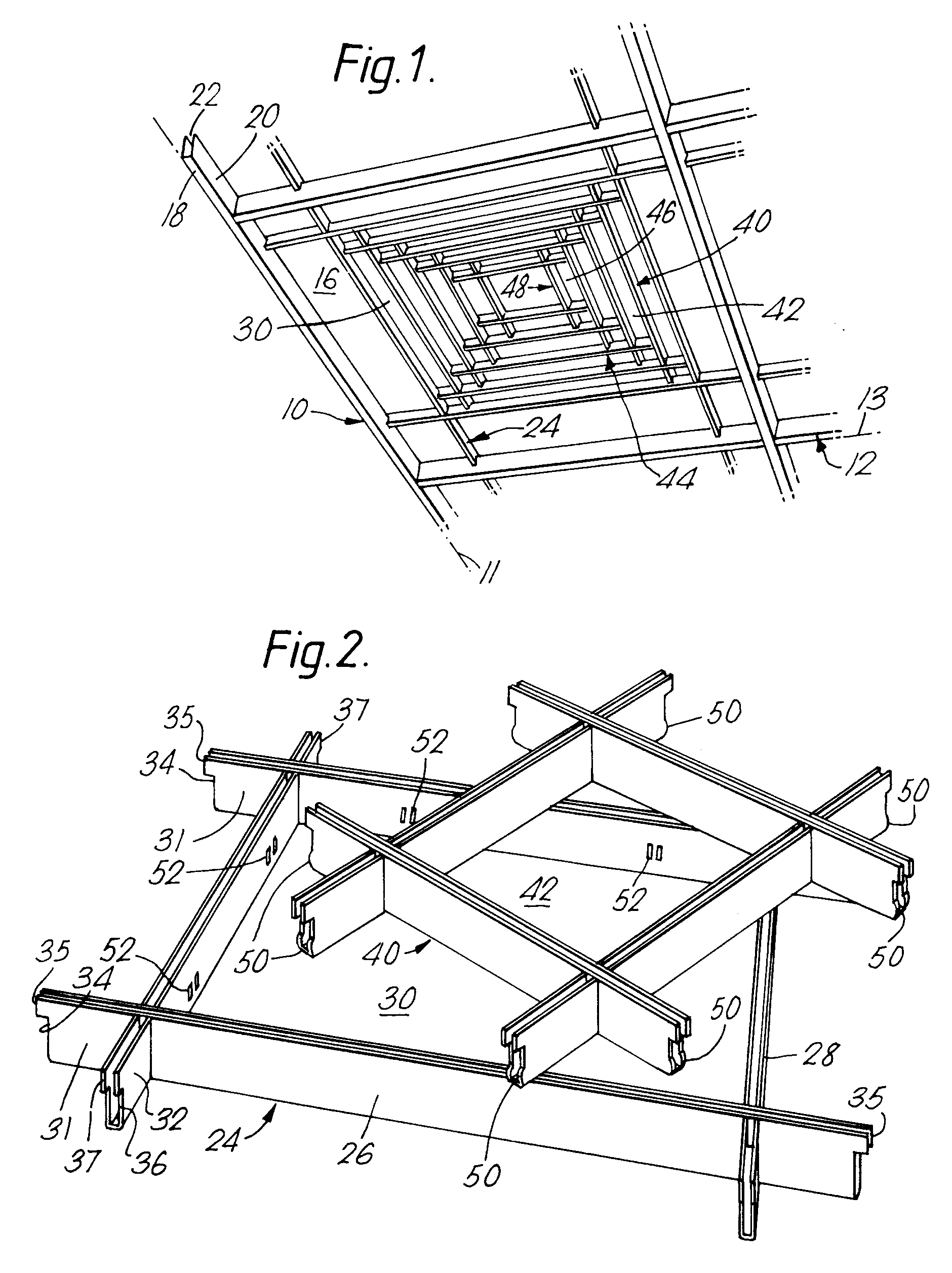
Figure 1 is a perspective view showing a portion of one embodiment of grid ceiling
according to the invention;
Figure 2 shows, in perspective, first and second grid elements of the ceiling of Figure
1, prior to being assembled; and
Figure 3 is a view similar to Figure 1, but showing a larger portion of a second embodiment
of grid ceiling according to the invention.
[0008] Referring first to Figure 1, there is illustrated therein a presently preferred embodiment
of grid ceiling according to the invention. This comprises a support grid comprising
a plurality of elongate first support members 10, having longitudinal parallel axes
11 and a variety of elongate second support members 12, the second support members
having parallel longitudinal axes 13 angled in the embodiment illustrated at right
angles to the axes 11 effective to define therewith the grid with polygonal in this
instance, rectangular first openings 16 therein.
[0009] The support members 10,12 in this construction are each in the form of U-profiled
sheet metal members having a lower web 18, side flanges 20 these having inturned rims
22 at their upper edges.
[0010] Mounted within some, or all, of the openings 16 are first grid elements 24 which
are each formed of a plurality of first elongate grid members 26 (Figure 2) and second
elongate grid members 28, defining a central second opening 30. The grid members 26,28
are again each of U-profiled sheet metal, similar to the support members 10,12 and
they may be formed of the same cross section material or, as shown, of smaller cross
section material. The grid members 26 each have intermediate their ends cutouts extending
upwardly from the web portion of the grid member 26 to about half the height of the
grid member 26 while the second grid members 28 have similar, complementary cutouts
whereby the members 26,28 can be interfitted, as shown in the drawings, to define
end portions 31,32 which are notched at 34,36. The distance between the ends of the
grid members 26, defined by the notches 34 at the ends thereof, is chosen to be a
close fit between the side walls or flanges 20 of the support members 12 so that the
unnotched portions 35 thereof rest on the rims 22 and prevent the grid moving in that
direction.
[0011] Similarly the lengths of the grid members 28 between the notched portions 36, at
the ends thereof, is adapted to the spacing between the support members 10 so that
the unnotched portions 37 of grid members 28 rests on the rims of the support members
10.
[0012] In a similar way, second grid elements 40, which are identical, but of smaller dimensions,
are mounted in the openings 30 and define a third opening 42 in which a third grid
element 44, again of identical but smaller construction is mounted. This again defines
a further central opening 46 in which a further grid element 48 is mounted.
[0013] In the embodiment shown, because of the provision of the notches 36 in each of the
grid members, these notches extending approximately 2/3rds of the way up the length
of the associated grid member, each grid element is mounted higher than the support
grid, the second grid element is mounted higher than the first grid element and so
on. In this way a generally pyramidal structure can be provided.
[0014] For internal use, the grid elements may simply be retained in place by gravity. For
external use, where the assembly may be subjected to winds and other environmental
problems, it may be advantageous for the grid elements to have means positively to
retain them in place and for this reason there is illustrated in Figure 2 a rounded
protrusion 50 on the end of each notched end portion 34,36 and this is adapted to
be engaged in a corresponding opening in the adjacent support member 10,12. Second
and subsequent grid elements may be retained by similar protrusions engaging in similar
corresponding openings 52 of a surrounding grid element.
[0015] In the second embodiment of ceiling shown in Figure 3, like parts have been indicated
by like reference numerals. As before, there are a plurality of elongate first support
members 10 and elongate second support members 12 defining rectangular first openings
16 therein. Mounted within these openings 16 are first grid elements 24 which are
each formed of a plurality of first elongate grid members 26 and second elongate grid
members 28, in a similar manner to that described above. The second grid elements
again define a second central opening 30 in which is mounted, in a similar way, second
grid elements 40 which are identical, but of smaller dimensions with the first grid
elements 24 and define a third opening 42.
[0016] At this point, however, there is a variation as compared with that of the first embodiment.
In the third opening 42 is mounted a different form of third grid element 60. In this
construction the third grid element 60 consists of a cross-shaped member defined by
a first elongate element 62 and a second elongate element 64. It will be seen that
this gives rather a different visual effect.
[0017] At the centre of the grid shown in Figure 3 there is mounted a further possible "third
element", namely, a light fitting 70. It will be appreciated that in a given ceiling
several such light fittings could be mounted at appropriate locations.
[0018] The structure of the present invention is therefore very well adapted to significant
variations to suit the requirements of a particular ceiling designer desiring to give
a particular visual and/or lighting effect.
1. A grid ceiling comprising a plurality of elongate first support members (10), said
first support members (10) having parallel longitudinal axes (11); a plurality of
elongate second support members (12), said second support members (12) having parallel
longitudinal axes (13) angled with respect to the longitudinal axes (11) of the first
support members (10), to define therewith a grid with polygonal first openings (16)
therein; a first grid element (24) inserted in at least one of said first openings
(16), the or each first grid element (24) defining therein at least one second opening
(30), said first grid element (24) comprising a plurality of elongate grid members
(26,28) effective to define said at least one second opening (30), whereby said at
least one second opening is of polygonal shape, the first and second support members
each being U-profiled sheet metal members, the grid members of the first grid element
(24) each having the same or a smaller U-profile cross-section than the support members
(10,12), characterised in that, a second smaller grid element (40) is inserted in
said at least one second opening (30) of the first grid element (24), or of at least
some of the first grid elements, said second grid element (40) comprising means defining
a third opening (42).
2. A grid ceiling according to claim 1, characterised in that the elongate grid members
of said first grid element (24) comprise first grid members (26) and second grid members
(28) angled with respect to said first grid members (26).
3. A grid ceiling according to claim 1 or 2, characterised in that further elongate grid
members of said at least one second grid element (40) are angled with respect to one
another and shorter in length than the relevant parallel extending first and second
grid members (26,28).
4. A grid ceiling according to claim 1, 2 or 3, characterised in that the U-profile sheet
metal members have inturned rims (22) at their upper edges and in that the lower portion
of each end portion (31,32) of the first grid members (26,28) are notched (34,36),
the unnotched portions (35,37) thereof resting on the rims (22) of the support members
(10,12) so that when the first grid element (24) is inserted in said first opening
(16), the level of the lower web of the first grid members (26,28) is higher than
the level of the lower web (18) of the support members (10,12).
5. A grid ceiling according to any preceding claim, characterised in that the second
grid members of the second grid element (40) have a cross section which is identical
to the cross section of the first grid members (26,28), and in that the lower portion
of each end portion of the second grid members are notched, the unnotched portions
thereof resting on the rims of the first grid members (26,28), so that when the second
grid element (40) is inserted in said second opening (30) the level of the lower web
of the U-profile second grid members is higher than the level of the U-profile of
the lower web (18) of the support members (10, 12).
6. A grid ceiling as claimed in any preceding claim, characterised in that said second
support members are arranged perpendicular to said first support members whereby said
first openings are substantially rectangular.
7. A grid ceiling as claimed in any preceding claim, characterised in that said first
grid members are arranged perpendicular to one another, whereby said second openings
are substantially rectangular.
8. A grid ceiling as claimed in any preceding claim, characterised in that said second
grid members are arranged substantially perpendicular to each other.
9. A grid ceiling as claimed in any preceding claim, and further comprising means defining
a third opening (42) in the or each said second grid element (40) and a third grid
member (44,60,70) mounted in said third opening (42).
10. A grid ceiling as claimed in any preceding claim, and further comprising means defining
a third opening in the or each second grid element (40) and a light fitting in at
least some of said third openings.
11. A grid ceiling according to claim 9, characterised in that said third grid member
comprises a cross-shaped member (60) defined by further elongate elements (62,64).
1. Rasterdecke, ausgestattet mit
- mehreren langgestreckten ersten Traggliedern (10) mit parallelen Längsachsen (11);
- mehreren langgestreckten zweiten Traggliedern (12) mit parallelen Längsachsen (13),
die zu den Längsachsen (11) der ersten Tragglieder (10) winklig angeordnet sind, um
mit diesen ein Raster mit darinliegenden ersten Öffnungen (16) zu bilden, die jeweils
die Form eines Vielecks aufweisen;
- einem ersten Rasterelement (24), das in mindestens eine dieser ersten Öffnungen
(16) eingesetzt ist, wobei dieses (bzw. jedes) erste Rasterelement (24) in seinem
Inneren mindestens eine zweite Öffnung (30) aufweist und mehrere langgestreckte Rasterglieder
(26,28) umfaßt, die diese mindestens eine zweite Öffnung (30) bilden, und wobei diese
mindestens eine zweite Öffnung (30) die Form eines Vielecks aufweist und die ersten
und zweiten Tragglieder jeweils aus U-förmigen Blechprofilen bestehen und der Querschnitt
der U-Profile der Rasterglieder des ersten Rasterelements (24) jeweils genauso groß
bzw. kleiner als derjenige der Tragglieder (10,12) ist;
dadurch gekennzeichnet, daß in der mindestens einen zweiten Öffnung (30) des ersten Rasterelements (24) oder
zumindest in einigen der ersten Rasterelemente ein zweites, kleineres Rasterelement
(40) eingesetzt ist, welches Mittel umfaßt, die eine dritte Öffnung (42) bilden.
2. Rasterdecke gemäß Anspruch 1, dadurch gekennzeichnet, daß die langgestreckten Rasterglieder des ersten Rasterelementes (24) erste Rasterglieder
(26) sowie zu diesen Rastergliedern (26) winklig angeordnete zweite Rasterglieder
(28) umfassen.
3. Rasterdecke gemäß einem der Ansprüche 1 oder 2, dadurch gekennzeichnet, daß weitere langgestreckte Rasterglieder des mindestens einen zweiten Rasterelementes
(40) winklig zueinander angeordnet und dabei kürzer als die sich jeweils parallel
erstreckenden ersten und zweiten Rasterglieder (26,28) sind.
4. Rasterdecke gemäß einem der Ansprüche 1, 2 oder 3, dadurch gekennzeichnet, daß die U-förmigen Blechprofile an ihrem oberen Rand nach innen gerichtete Kanten (22)
aufweisen und im unteren Bereich jedes Endteils (31,32) der ersten Rasterglieder (26,28)
Aussparungen vorhanden sind, wobei deren nicht ausgesparte Teile (35,37) auf den Kanten
(22) der Tragglieder (10,12) so aufliegen, daß beim Einlegen des ersten Rasterelements
(24) in die erste Öffnung (16) der untere Steg der ersten Rasterglieder (26,28) jeweils
oberhalb des unteren Steges (18) der Tragglieder (10,12) zu liegen kommt.
5. Rasterdecke gemäß einem der vorstehenden Ansprüche, dadurch gekennzeichnet, daß der Querschnitt der zweiten Rasterglieder des zweiten Rasterelementes (40) gleich
demjenigen der ersten Rasterglieder (26,28) ist und im unteren Bereich jedes Endteils
der zweiten Rasterglieder Aussparungen vorhanden sind, wobei deren nicht ausgesparte
Teile auf den Kanten der ersten Rasterglieder (26,28) so aufliegen, daß beim Einlegen
des zweiten Rasterelements (40) in die zweite Öffnung (30) der untere Steg des U-Profils
der zweiten Rasterglieder jeweils oberhalb des U-Profils des unteren Steges (18) der
Tragglieder (10,12) zu liegen kommt.
6. Rasterdecke gemäß einem der vorstehenden Ansprüche, dadurch gekennzeichnet, daß die zweiten Tragglieder rechtwinklig zu den ersten Traggliedern angeordnet sind,
wobei die ersten Öffnungen eine im wesentlichen rechtwinklige Form aufweisen.
7. Rasterdecke gemäß einem der vorstehenden Ansprüche, dadurch gekennzeichnet, daß die ersten Rasterglieder zueinander rechtwinklig angeordnet sind, wobei die zweiten
Öffnungen eine im wesentlichen rechtwinklige Form aufweisen.
8. Rasterdecke gemäß einem der vorstehenden Ansprüche, dadurch gekennzeichnet, daß die zweiten Rasterglieder im wesentlichen rechtwinklich zueinander angeordnet sind.
9. Rasterdecke gemäß einem der vorstehenden Ansprüche, jedoch zusätzlich mit Mitteln,
die eine dritte Öffnung (42) in dem (bzw. jedem) zweiten Rasterelement (40) bilden,
sowie mit einem in dieser dritten Öffnung (42) montierten dritten Rasterglied ausgestattet.
10. Rasterdecke gemäß einem der vorstehenden Ansprüche, jedoch zusätzlich mit Mitteln,
die eine dritte Öffnung (42) in dem (bzw. jedem) zweiten Rasterelement (40) bilden,
sowie mit Leuchten in mindestens einigen dieser dritten Öffnungen ausgestattet.
11. Rasterdecke gemäß Anspruch 9, dadurch gekennzeichnet, daß das genannte dritte Rasterglied ein kreuzförmiges Glied (60) umfaßt, das von weiteren
langgestreckten Elementen (62,64) gebildet wird.
1. Plafond en treillis comprenant une pluralité de premiers membres supports allongés
(10), les dits premiers membres supports allongés (10) ayant des axes longitudinaux
parallèles (11) ; une pluralité de seconds membres supports allongés (12), les dits
seconds membres supports (12) ayant des axes longitudinaux parallèles (13) décalés
angulairement par rapport aux axes (11) des premiers membres supports allongés (10),
pour définir avec ces derniers un treillis comportant des premières ouvertures polygonales
(16), à l'intérieur ; un premier élément de treillis (24) inséré dans au moins une
des dites premières ouvertures (16), l'un ou chacun des premiers éléments de treillis
(24) définissant à l'intérieur au moins une seconde ouverture (30), le dit premier
élément de treillis (24) comprenant une pluralité de membres de treillis allongés
(26, 28) pour définir de façon efficace au moins la dite seconde ouverture (30), moyen
par lequel au moins la dite seconde ouverture (30) est de forme polygonale, les premier
et second membres supports étant chacun des membres en feuilles de métal profilés
en forme de U, les membres de treillis du premier élément de treillis (24) chacun
ayant la même ou une plus petite section transversale, profilée en forme de U, que
les membres supports (10, 12), caractérisé en ce que, un second élément de treillis
plus petit (40) est inséré dans la dite seconde ouverture (30) au moins du premier
élément de treillis (24), ou dans au moins certains des premiers éléments de treillis,
le dit second élément de treillis (40) comprenant des éléments définissant une troisième
ouverture (42).
2. Plafond en treillis selon la revendication 1, caractérisé en ce que les membres de
treillis allongés du dit premier élément de treillis (24) comprennent des premiers
membres de treillis (26) et des seconds membres de treillis (28) décalés angulairement
par rapport aux dits premiers membres de treillis (26).
3. Plafond en treillis selon les revendications 1 ou 2, caractérisé en ce que des membres
de treillis allongés supplémentaires du dit second élément de treillis (40) au moins,
sont décalés angulairement les uns par rapport aux autres et de longueur plus petite
que les premiers et seconds membre de treillis (26, 28) qui s'y rapportent et qui
s'étendent parallèlement à ces derniers.
4. Plafond en treillis selon les revendications 1, 2 ou 3, caractérisé en ce que les
membres en feuille de métal profilés en U possèdent des rebords (22) repliés vers
l'intérieur au niveau de leurs bords supérieurs et en ce que la partie inférieure
de chaque portion terminale (31, 32) des premiers membres de treillis (26, 28) possède
une encoche en (34, 36), les portions non entaillées (35, 37) de ces derniers reposant
sur les rebords (22) des membres supports allongés (10, 12) de telle sorte que lorsque
le premier élément de treillis (24) est inséré dans la dite première ouverture (16),
le niveau de l'âme inférieure des premiers membres de treillis (26, 28) est plus élevé
que le niveau de l'âme inférieure (18) des membres supports allongés (10, 12).
5. Plafond en treillis selon l'une quelconque des revendications précédentes, caractérisé
en ce que les seconds membres de treillis du second élément de treillis (40) possèdent
une section transversale qui est identique à la section transversale des premiers
membres de treillis (26, 28), et en ce que la partie inférieure de chaque portion
terminale des seconds membres de treillis est taillée en encoche, les portions non
entaillées de ces derniers reposant sur les rebords des premiers membres de treillis
(26, 28), de telle sorte que lorsque le second élément de treillis (40) est inséré
dans la dite seconde ouverture (30), le niveau de l'âme inférieure des seconds membres
de treillis profilés en forme de U soit plus élevé que le niveau de l'âme inférieure
(18) profilée en forme de U des membres supports (10, 12).
6. Plafond en treillis comme revendiqué dans l'une quelconque des revendications précédentes,
caractérisé en ce que les dits seconds membres supports sont disposés perpendiculairement
aux dits premiers membres supports, arrangement par lequel les dites premières ouvertures
sont substantiellement rectangulaires.
7. Plafond en treillis comme revendiqué dans l'une quelconque des revendications précédentes,
caractérisé en ce que les dits premiers membres de treillis sont disposés perpendiculairement
les uns par rapport aux autres, arrangement par lequel les dites secondes ouvertures
sont substantiellement rectangulaires.
8. Plafond en treillis comme revendiqué dans l'une quelconque des revendications précédentes,
caractérisé en ce que les dits seconds membres de treillis sont substantiellement
disposés perpendiculairement les uns par rapport aux autres.
9. Plafond en treillis comme revendiqué dans l'une quelconque des revendications précédentes,
et comprenant de plus, des éléments définissant une troisième ouverture (42) dans
le dit ou dans chaque dit second élément de treillis (40) et un troisième membre de
treillis (44, 60, 70) monté dans la dite troisième ouverture (42).
10. Plafond en treillis comme revendiqué dans l'une quelconque des revendications précédentes,
et comprenant de plus, des éléments définissant une troisième ouverture dans le dit
ou dans chaque dit second élément de treillis (40) et un accessoire lumineux dans
au moins certaines des dites troisièmes ouvertures.
11. Plafond en treillis selon la revendication 9, caractérisé en ce que le dit troisième
membre de treillis comprend un membre en forme de croix (60) défini par de nouveaux
éléments allongés (62, 64).