| (19) |
 |
|
(11) |
EP 0 480 894 A1 |
| (12) |
EUROPEAN PATENT APPLICATION |
| (43) |
Date of publication: |
|
15.04.1992 Bulletin 1992/16 |
| (22) |
Date of filing: 26.09.1991 |
|
| (51) |
International Patent Classification (IPC)5: B01F 7/00 |
|
| (84) |
Designated Contracting States: |
|
AT DE FR GB IT |
| (30) |
Priority: |
05.10.1990 SE 9003188
|
| (71) |
Applicant: ITT Flygt Aktiebolag |
|
S-171 25 Solna (SE) |
|
| (72) |
Inventor: |
|
- Hovstadius, Gunnar
S-193 00 Sigtuna (SE)
|
| (74) |
Representative: Larsson, Sten |
|
ITT FLYGT AB
Box 1309
S-171 25 Solna
S-171 25 Solna (SE) |
|
| |
|
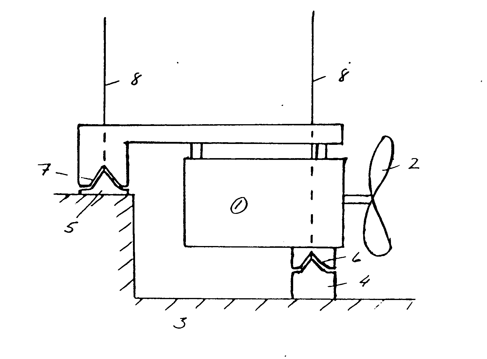
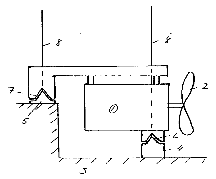
(57) The invention concerns a device for an easily releasable mounting of a submersible
mixer in a liquid tank.
At the bottom of the tank there are provided supports (4), (5), while the under side
of the mixer is provided with corresponding openings (6), (7) for receiving the supports.
In order to prevent the reaction force from the propeller (2) from tilting the front
end of the mixer upwards, at least one of the supports (5) is arranged at a level
above the level of the propeller shaft.
|
|
[0001] The invention concerns a device for an easily releasable connection of a submersible
mixer within a liquid tank.
[0002] In tanks containlng liquids with large amounts of solid bodies, mixers are often
used to prevent sedimentatlon and to secure that the liquid is kept homogeneous. A
type of mixer which has become very common for this purpose is the so-called submersible
mixer which comprises an electric motor with or without a gear box and a propeller.
The machine is normally arranged to be lowered along a vertical guide which is mounted
within the tank in a suitable way. The advantage with this machine is above all that
it is very easy to take up for service and in addition it is very easy to arrange
in different directions by turning of the guide. A device of this type is shown in
Swedish Patent No 8502389-3.
[0003] When the mixer operates a considerable reaction force from the propeller occurs which
tries to press the mixer backwards and possibly tilt it upwards. By a suitable dimensioning
of the guide and the connection between the latter and the mixer, this force can be
taken care of and the mixer retains its preferred position.
[0004] The known device mentioned above has the disadvantage that it is relatively expensive
and thus, it has been a desire to replace it by a more simple device when the conditions
are such, that the mixer is meant to operate in one position only, without having
the possibility to turn. A device of this type is shown in DE P 3900 630.1. Here,
the guide is designed like a tripod and is attached to the bottom of the tank, the
mixer being lowered to its operating position on a shelf adjacent the branching of
the guide. In order to stand the reaction force from the propeller, the guide system
must by very rigid which means costs, especially if the tank contains corrosive liquid
which calls for parts made of stainless steel.
[0005] According to the invention, the above mentioned problems have been solved by help
of the device which is stated in the claims.
[0006] The invention is described more closely below with reference to the enclosed drawing,
which shows the device according to the invention seen from aside.
[0007] In the drawings 1 stands for a motor and 2 for a propeller. 3 stands for the bottom
of a tank, 4 and 5 supports, 6 and 7 openings in the rack of the mixer and 8 guide
wires.
[0008] At the bottom of the tank there are a number of cone-formed supports 4 and 5 arranged
on which the mixer shall rest during operation. In order to guide the mixer towards
the supports during lowering, the supports are provided with guide wires 8, which
extend vertically upwards to the brim of the tank and which go through openings 6,
7 in the mixer or in its rack. The openings 6, 7 are formed like cone-formed shells
which are adapted to the supports 4, 5. This means that the mixer stands rigidly on
the supports after having been lowered along the guide wires 8. Said wires may then
be brought aside and attached to the wall of the tank in order not to disturb the
mixing process.
[0009] In order to secure that the reaction force from the propeller 2 will not cause the
device to tilt upwards, the supports 5 situated away from the propeller are placed
at a higher level than the supports 4 adjacent the propeller and also above the level
of the propeller shaft. This means that the reaction force from the propeller will
act below the supports 5 and thus press the mixer downwards instead of tilting it
upwards.
[0010] The great advantage with the device is thus that a simple and stable support of the
mixer is obtained when no changing of the inclination of the mixer is desired. The
guiding of the mixer towards its operating position along the guide wires is a non-expensive
solution as compared with the guide pipes which are normally used.
1. A device for an easily releasable mounting of a submersible mixer comprising an electric
motor (1) and a propeller (2) on a substantially horizontal driving shaft in a liquid
tank, the mixer in its operating position being supported by a number of cone-formed
supports (4), (5) which enter corresponding openings (6), (7) on the under side of
the mixer or on an attached mixer rack, characterized in that the supports (4), (5)
are so positioned that at least two (4) are arranged near the front end of the mixer
by the propeller (2), while at least one support (5) is arranged near the other end
of the mixer and at a level higher than the level of the previously mentioned and
also higher than the level of the propeller shaft, thus preventing the reaction force
from the propeller to raise the front end of the mixer during operation.
2. A device according to claim 1, characterized in, that to the cone-formed supports
(4), (5) are connected vertically directed guide means, such as wires (8), along which
the mixer is moved during lowering and raising.