|
(11) | EP 0 489 563 B1 |

| (12) | EUROPEAN PATENT SPECIFICATION |
|
|
| (54) |
Method of detecting a deflated tyre on a vehicle Verfahren zur Feststellung eines leeren Reifens an einem Fahrzeug Méthode de détection du dégonflage d'un pneumatique sur un véhicule |
|
|
|||||||||||||||||||||||||||||||
| Note: Within nine months from the publication of the mention of the grant of the European patent, any person may give notice to the European Patent Office of opposition to the European patent granted. Notice of opposition shall be filed in a written reasoned statement. It shall not be deemed to have been filed until the opposition fee has been paid. (Art. 99(1) European Patent Convention). |
[0001] This invention relates to a method of detecting a deflated tyre on a vehicle suitable for cars, trucks and the like, and particularly to the system disclosed in for example French Patent Publication FR-A-2 568 519 and European Patent Publication EP-A-0 291 217.
[0002] These patent applications propose using the wheel speed signals from the vehicle wheels such as for example a multi-pulse signal as used for ABS equipment or a single-pulse signal for each rotation of each wheel. They compare the speed derived signals of the wheels on a diagonal sum basis by differencing the sums of the speeds of the diagonally opposed pairs of wheels and this is monitored looking for a difference above a critical level. In the case of the French Patent application FR-A-2 568 519 error problems due to cornering and acceleration etc were allowed for by making the period of checking a very long distance or time so that the effect of cornering and braking was averaged out.
[0003] In the case of the European Patent Publication EP-A-0 291 217 the system first calculats the lateral and longitudinal accelerations of the vehicle and by setting strict limits in which the system was inhibited thereby avoiding false signals. This system goes on to look at the speed of each wheel compared with the mean of the set of wheels to detect which of the four wheels was in fact punctured. However the system is not able to reliably detect two simultaneous punctures because these may give the same effect as cornering or braking or accelerating depending which two are deflated and therefore resulted in inhibition of the system.
[0004] It is an object of the present invention to add to the prior art systems using diagonal sum comparisons further features allowing correct identification of punctures including two simultaneous punctures.
[0005] According to the present invention a method of detecting a deflated tyre on a vehicle by comparing the rolling radii of the tyres by means of comparing angular velocity signals from wheel speed sensors at each wheel is characterised by calculating the factors
where C1, C2, C3 and C4 are the signals for the speeds of the front left-hand, front right-hand, rear left-hand and rear right-hand wheels of the vehicle, monitoring these factors and if the value of one or more factor becomes greater than 1.0005 or less than 0.9995 producing a warning signal to indicate that a tyre has become partially or completely deflated.
[0006] More preferably a warning signal is indicated when the value of one of the factors becomes greater than 1.001 or less than 0.999. In each case the other factors remain substantially one, the small variations being due to noise in the signals.
[0007] Preferably a warning signal is only given after two or more, or more preferably five successive time periods during which monitoring shows that one or more of the factors is greater than the specified limit, this being to avoid potential false signals.
[0008] The system may also determine which wheel or pair of wheels is deflated by means of comparing all the factors with a Truth Table as follows:
[0009] In this Table +ve means the factor is greater than 1.0005, -ve means the factor is less than 0.9995 and zero means that the factor is substantially one.
[0010] To ensure that false signals are not given it is preferable to correct the wheel speed signals to allow for different tyre sizes and other variations by calculating constants for correcting the speed signals by running the vehicle in a straight line at a constant speed.
[0011] Preferably the signals comprise multi-pulse electrical signals from each wheel of the type used for an anti-lock braking system. Alternatively the signals may comprise a single electrical pulse for each rotation of each wheel and the time period between successive pulses is used for the angular velocity value.
[0012] Further aspects of the present invention will become apparent from the following description by way of example only of one embodiment.
[0013] The device comprises a central computer or processor which takes the speed signals from each of the four wheels of the car. These signals can be the usual multi-pulse (i.e. 48 or 96 pulses per wheel), such as the electrical signals which are used for anti-lock braking systems of the electronic type or may instead be a single pulse per wheel generated by a magnet attached to the wheel or brake disc and a stationary pick-up attached to the suspension. The first type of signal is a digital signal and the second is a single pulse signal but both have the ability to generate signal proportional to the wheel speed. In the latter case this signal is most conveniently generated by means of the time for a single rotation.
[0014] In the case of the single pulse system it is necessary to set up a computer derived speed signal generating system for each of the wheels so that the true speeds at any single instant of all four wheels can be determined. Such a process is described in our co-pending UK Patent Application No 9002925.7, published as EP-A-0 441 600 and US-A-5 192 929.
[0015] The four signals are taken to the computer or central processing unit and converted to four separate signals directly proportional to the speed of each of the four wheels. A compensation to allow for variations between the different tyres of a vehicle because in fact they are tolerances on tyres and other simple car factors such as front and rear weight variation which may cause slight differences in the rolling radius of the tyres on the vehicle can be achieved by means of a precalibration to determine constants used to correct the speeds. This is carried out at a constant speed in straight running but is not a particularly important part of the present invention and further detail will not be here given.
[0016] The four wheel speed signals C1, C2, C3 and C4 are those calculated by the first stages of the computer. The computer then calculates the factors
These factors are stored. As long as the four tyres of the vehicle are substantially at the same pressure these factors all remain substantially at one although there is some small variation usually less than 0.0004 due to noise from the electrical signals.
[0017] If one or more of these factors exceeds 1.0005 or less than 0.9995 in value then one of the tyres has a relative pressure deflation of 0.3 bar or more difference to the others. The device then produces a warning signal which indicates on the dashboard by illuminating a light that a tyre has been partially or completely deflated. To avoid false errors this signal does not in fact produce a warning signal until five successive time periods of five seconds have given a constant signal greater than 1.0005 or less than 0.9995.
[0018] The signal level for a warning may also be set at greater than 1.001 or less than 0.999 which is equivalent to 0.6 bar pressure loss in a single tyre.
[0019] The computer also compares the factors calculated with the following Truth Table which allows it to determine whether tyre 1, tyre 2, tyre 3, tyre 4 or indeed combinations of two or three of these tyres are deflated.
[0020] In this Table +ve means the factor is greater than 1.0005, -ve means the factor is less than 0.9995 and 0 means that the factor is substantially one.
1. A method of detecting a deflated tyre on a vehicle by comparing the rolling radii
of the tyres by means of comparing angular velocity signals from wheel speed sensors
at each wheel characterised by calculating the factors
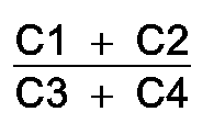
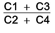
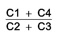
where C1, C2, C3 and C4 are the signals for the speeds of the front left-hand, front right-hand, rear left-hand and rear right-hand wheels of the vehicle, monitoring these factors and if the value of one or more factor becomes greater than 1.0005 or less than 0.9995 producing a warning signal to indicate that a tyre has become partially or completely deflated.
where C1, C2, C3 and C4 are the signals for the speeds of the front left-hand, front right-hand, rear left-hand and rear right-hand wheels of the vehicle, monitoring these factors and if the value of one or more factor becomes greater than 1.0005 or less than 0.9995 producing a warning signal to indicate that a tyre has become partially or completely deflated.
2. A method according to Claim 1 characterised in that a warning signal is indicated
when the value of the factors becomes greater than 1.001 or less than 0.999.
3. A method according to Claim 1 or 2 characterised in that the warning signal is only
given after the value of a factor is in the claimed range for two successive time
periods.
4. A method according to Claim 1 or 2 characterised in that a warning signal is only
given after the value of a factor is in the claimed range for five successive time
periods.
5. A method according to any of Claims 1 to 4 characterised in that the comparison of
the factors is by means of the Truth Table
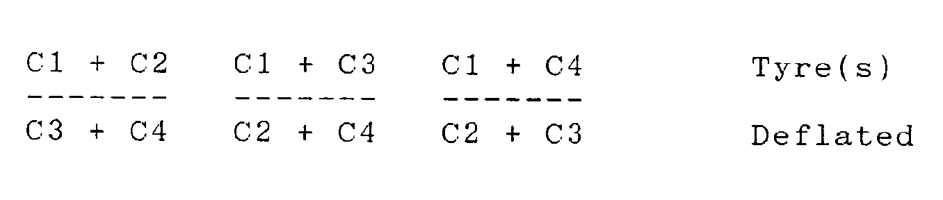
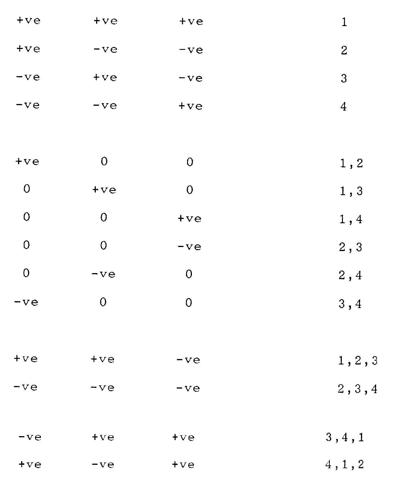
where +ve or -ve means that a factor is greater or less than the set values respectively and the tyre or tyres deflated are thus determined.
where +ve or -ve means that a factor is greater or less than the set values respectively and the tyre or tyres deflated are thus determined.
6. A method according to any of Claims 1 to 5 characterised in that the signals for the
speeds are corrected relative to one another based on constants derived from straight
line running of the vehicle at a single speed.
7. A method according to any of Claims 1 to 6 characterised in that the signals comprise
multipulse electrical signals from each wheel of the type used for an anti-lock braking
system.
8. A method according to any of Claims 1 to 6 characterised in that the signals comprise
a single electrical pulse for each rotation of each wheel and the time period between
successive pulses is used for the angular velocity value.
1. Ein Verfahren zum Nachweisen eines zumindest teilweise entlüfteten Reifens an einem
Fahrzeug durch Vergleichen der Roliradien der Reifen, indem Winkelgeschwindigkeitssignale
von Radgeschwindigkeitssensoren an jedem Rad verglichen werden,
dadurch gekennzeichnet,
daß die Faktoren
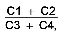
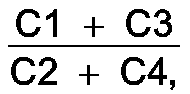
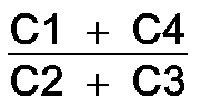
berechnet werden, wobei C1, C2, C3 und C4 die Signale für die Geschwindigkeiten des vorderen linken, des vorderen rechten, des hinteren linken und des hinteren rechten Rads des Fahrzeugs sind, daß diese Faktoren überwacht werden und daß, falls der Wert eines oder mehrerer Faktoren größer als 1.0005 oder kleiner als 0.9995 wird, ein Warnsignal erzeugt wird, um anzuzeigen, daß ein Reifen teilweise oder vollständig entlüftet worden ist.
dadurch gekennzeichnet,
daß die Faktoren
berechnet werden, wobei C1, C2, C3 und C4 die Signale für die Geschwindigkeiten des vorderen linken, des vorderen rechten, des hinteren linken und des hinteren rechten Rads des Fahrzeugs sind, daß diese Faktoren überwacht werden und daß, falls der Wert eines oder mehrerer Faktoren größer als 1.0005 oder kleiner als 0.9995 wird, ein Warnsignal erzeugt wird, um anzuzeigen, daß ein Reifen teilweise oder vollständig entlüftet worden ist.
2. Ein Verfahren nach Anspruch 1,
dadurch gekennzeichnet,
daß ein Warnsignal angezeigt wird, wenn der Wert der Faktoren größer als 1.001 oder kleiner als 0.999 wird.
dadurch gekennzeichnet,
daß ein Warnsignal angezeigt wird, wenn der Wert der Faktoren größer als 1.001 oder kleiner als 0.999 wird.
3. Ein Verfahren nach Anspruch 1 oder 2,
dadurch gekennzeichnet,
daß das Warnsignal lediglich abgegeben wird, nachdem sich der Wert eines Faktors im beanspruchten Bereich für zwei aufeinanderfolgende Zeitperioden befindet.
dadurch gekennzeichnet,
daß das Warnsignal lediglich abgegeben wird, nachdem sich der Wert eines Faktors im beanspruchten Bereich für zwei aufeinanderfolgende Zeitperioden befindet.
4. Ein Verfahren nach Anspruch 1 oder 2,
dadurch gekennzeichnet,
daß ein Warnignal lediglich abgegeben wird, nachdem sich der Wert eines Faktors im beanspruchten Bereich für fünf aufeinanderfolgende Zeitperioden befindet.
dadurch gekennzeichnet,
daß ein Warnignal lediglich abgegeben wird, nachdem sich der Wert eines Faktors im beanspruchten Bereich für fünf aufeinanderfolgende Zeitperioden befindet.
5. Ein Verfahren nach einem der Ansprüche 1 bis 4,
dadurch gekennzeichnet,
daß der Vergleich der Faktoren stattfindet mittels der Wahrheitstabelle
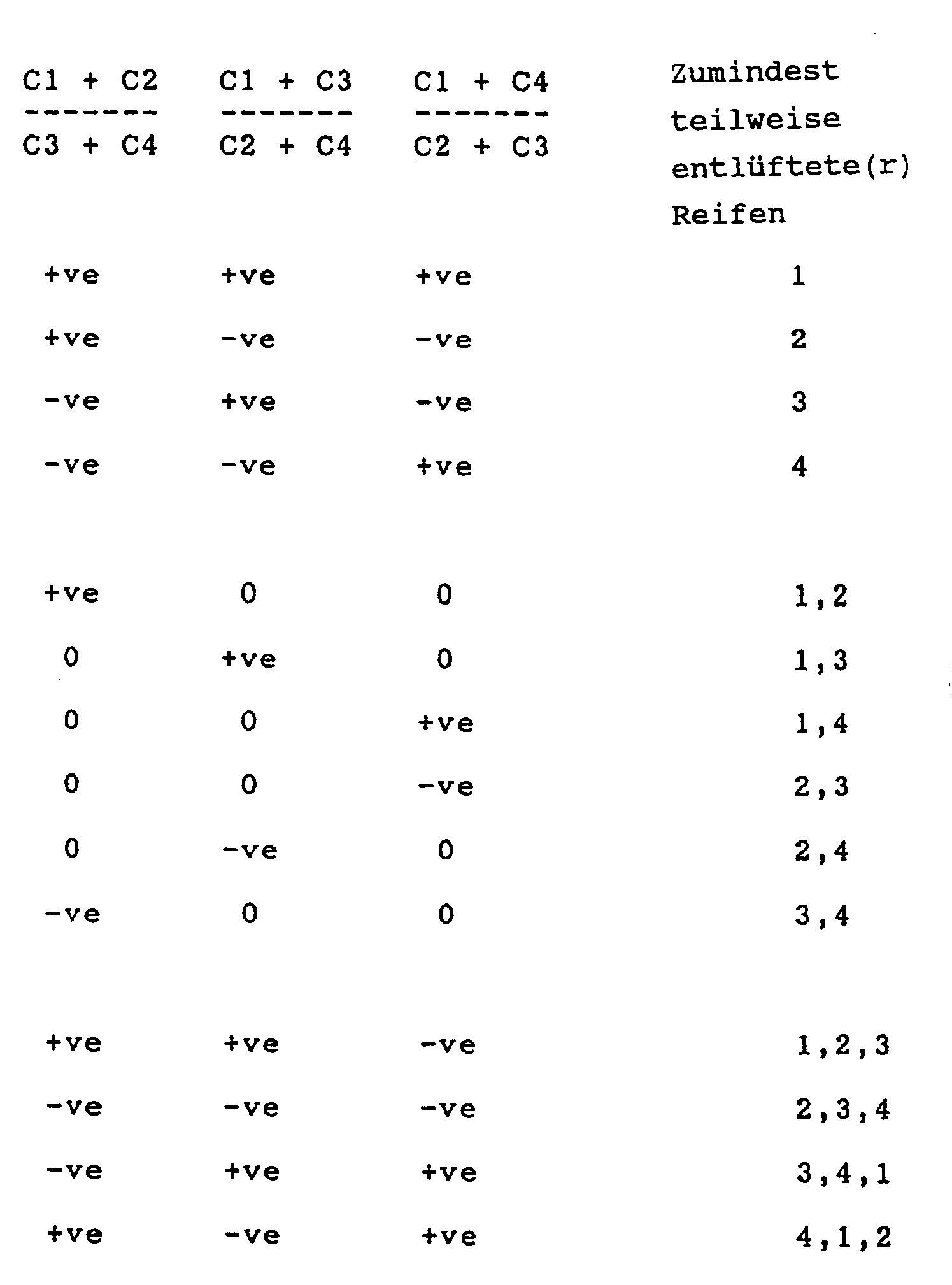
wobei +ve bzw. -ve bedeutet, daß ein Faktor größer bzw. kleiner als die eingestellten Werte ist, und daß der/die zumindest teilweise entlüftete/entlüfteten Reifen auf diese Weise bestimmt wird/werden.
dadurch gekennzeichnet,
daß der Vergleich der Faktoren stattfindet mittels der Wahrheitstabelle
wobei +ve bzw. -ve bedeutet, daß ein Faktor größer bzw. kleiner als die eingestellten Werte ist, und daß der/die zumindest teilweise entlüftete/entlüfteten Reifen auf diese Weise bestimmt wird/werden.
6. Ein Verfahren nach einem der Ansprüche 1 bis 5,
dadurch gekennzeichnet,
daß die Signale für die Geschwindigkeiten relativ zueinander korrigiert werden, und zwar gestützt auf Konstanten, die aus einem Geradeausfahrbetrieb des Fahrzeugs bei einer einzigen Geschwindigkeit abgeleitet werden.
dadurch gekennzeichnet,
daß die Signale für die Geschwindigkeiten relativ zueinander korrigiert werden, und zwar gestützt auf Konstanten, die aus einem Geradeausfahrbetrieb des Fahrzeugs bei einer einzigen Geschwindigkeit abgeleitet werden.
7. Ein Verfahren nach einem der Ansprüche 1 bis 6,
dadurch gekennzeichnet,
daß die Signale elektrische Multipulssignale von jedem Rad des Typs umfassen, der für ein Antiblockiersystem verwendet wird.
dadurch gekennzeichnet,
daß die Signale elektrische Multipulssignale von jedem Rad des Typs umfassen, der für ein Antiblockiersystem verwendet wird.
8. Ein Verfahren nach einem der Ansprüche 1 bis 6,
dadurch gekennzeichnet,
daß die Signale einen einzelnen elektrischen Puls für jede Drehung jedes Rads umfassen und die Zeitperiode zwischen aufeinanderfolgenden Pulsen für den Winkelgeschwindigkeitswert verwendet wird.
dadurch gekennzeichnet,
daß die Signale einen einzelnen elektrischen Puls für jede Drehung jedes Rads umfassen und die Zeitperiode zwischen aufeinanderfolgenden Pulsen für den Winkelgeschwindigkeitswert verwendet wird.
1. Procédé de détection d'un pneumatique dégonflé sur un véhicule, par comparaison des
rayons de roulement des pneumatiques obtenus par comparaison des signaux de vitesse
angulaire de capteur de vitesse de roue monté sur chaque roue, caractérisé par le
calcul des facteurs :

,

et

C1, C2, C3 et C4 étant les signaux de vitesse des roues avant gauche, avant droite, arrière gauche et arrière droite du véhicule, le contrôle de ces facteurs et, lorsque la valeur de l'un au moins des facteurs devient supérieure à 1,0005 ou inférieure à 0,9995, la création d'un signal d'avertissement destiné à indiquer qu'un pneumatique s'est dégonflé partiellement ou totalement.
,
et
C1, C2, C3 et C4 étant les signaux de vitesse des roues avant gauche, avant droite, arrière gauche et arrière droite du véhicule, le contrôle de ces facteurs et, lorsque la valeur de l'un au moins des facteurs devient supérieure à 1,0005 ou inférieure à 0,9995, la création d'un signal d'avertissement destiné à indiquer qu'un pneumatique s'est dégonflé partiellement ou totalement.
2. Procédé selon la revendication 1, caractérisé en ce qu'un signal d'avertissement est
indiqué lorsque la valeur des facteurs devient supérieure à 1,001 ou inférieure à
0,999.
3. Procédé selon la revendication 1 ou 2, caractérisé en ce que le signal d'avertissement
n'est donné qu'après que la valeur d'un facteur s'est trouvée dans la plage concernée
pendant au moins deux périodes consécutives de temps.
4. Procédé selon la revendication 1 ou 2, caractérisé en ce qu'un signal d'avertissement
n'est donné qu'après que la valeur d'un facteur s'est trouvée dans la plage indiquée
pendant cinq périodes successives.
5. Procédé selon l'une quelconque des revendications 1 à 4, caractérisé en ce que la
comparaison des facteurs est réalisée à l'aide de la table de vérité suivante :
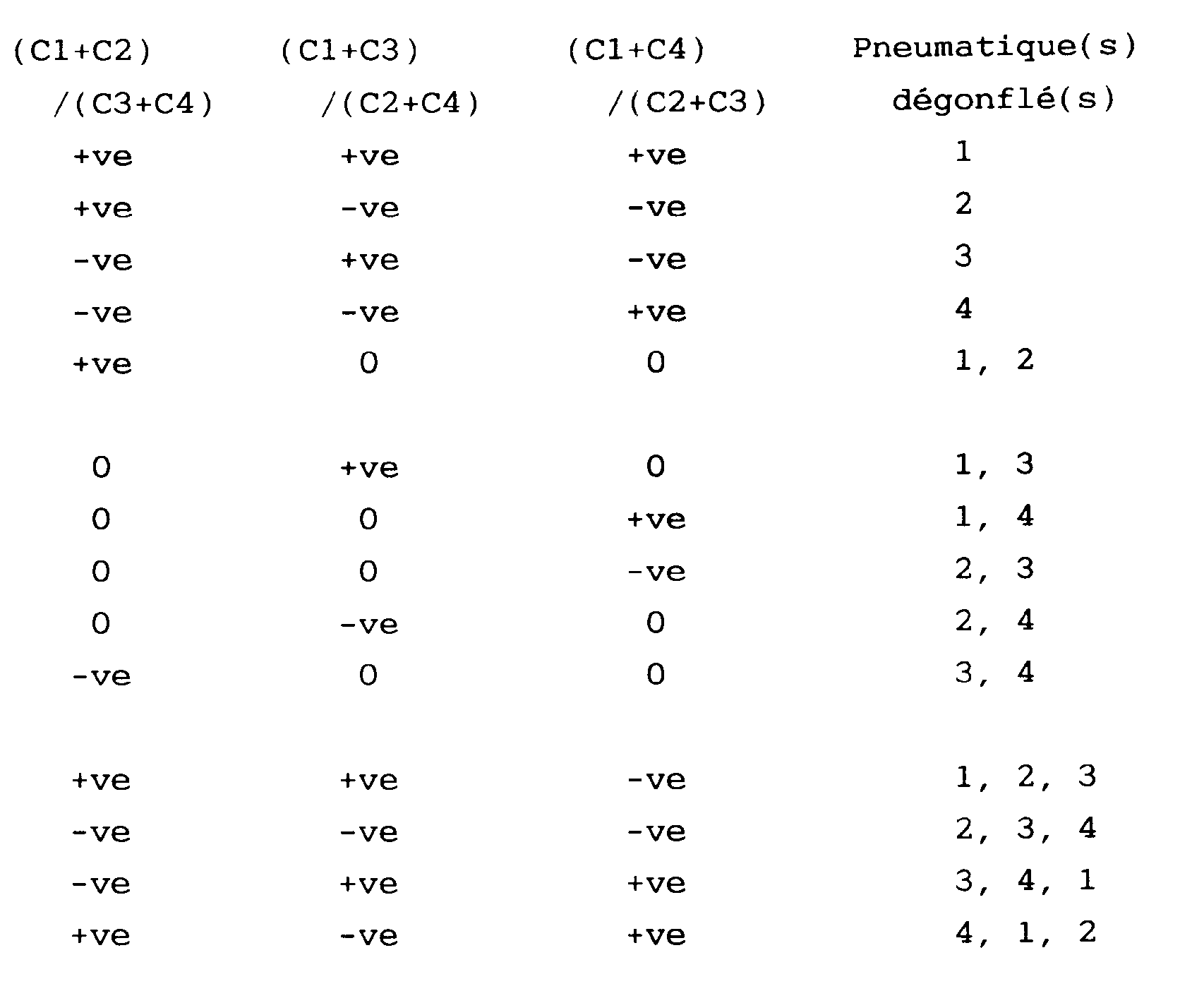
+ve ou -ve indiquant qu'un facteur est supérieur ou inférieur aux valeurs de consigne respectives, et le pneumatique ou les pneumatiques dégonflés sont ainsi déterminés.
+ve ou -ve indiquant qu'un facteur est supérieur ou inférieur aux valeurs de consigne respectives, et le pneumatique ou les pneumatiques dégonflés sont ainsi déterminés.
6. Procédé selon l'une quelconque des revendications 1 à 5, caractérisé en ce que les
signaux de vitesse sont corrigés les uns par rapport aux autres d'après les constantes
dérivées d'une conduite en ligne droite du véhicule à une seule vitesse.
7. Procédé selon l'une quelconque des revendications 1 à 6, caractérisé en ce que les
signaux sont des signaux électriques à plusieurs impulsions pour chaque roue, du type
utilisé dans un système de freinage antiblocage.
8. Procédé selon l'une quelconque des revendications 1 à 6, caractérisé en ce que les
signaux comprennent une seule impulsion électrique par tour de chaque roue, et la
période comprise entre les impulsions successives est utilisée comme valeur de vitesse
angulaire.