| (19) |
 |
|
(11) |
EP 0 505 451 B1 |
| (12) |
EUROPEAN PATENT SPECIFICATION |
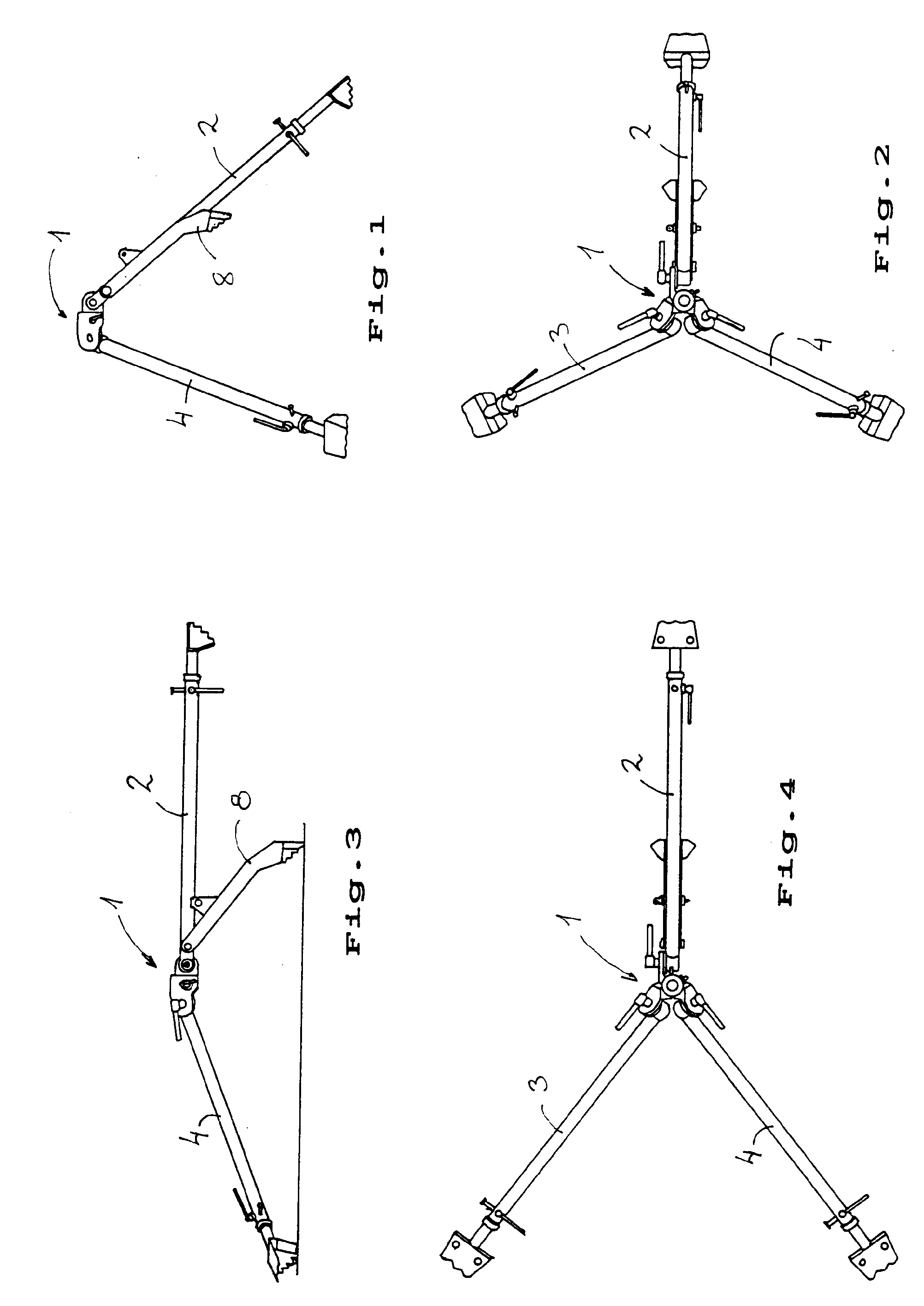
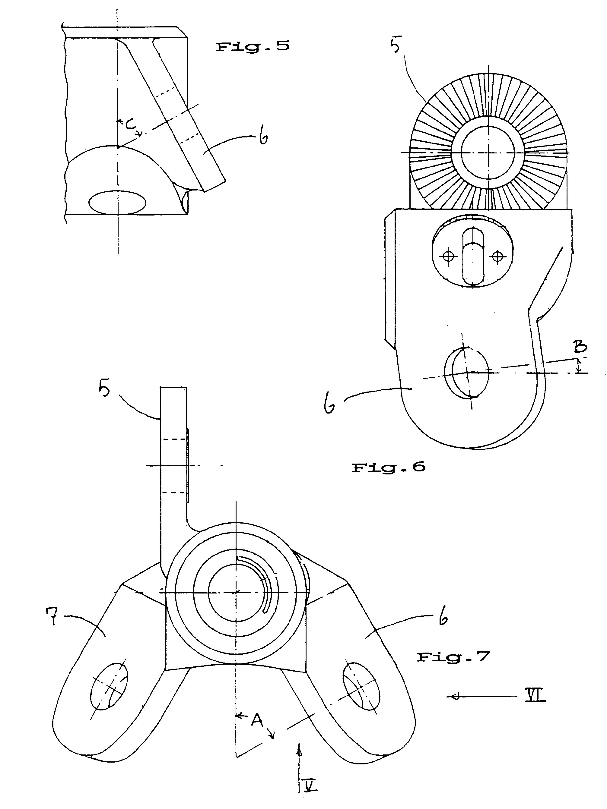
| (45) |
Mention of the grant of the patent: |
|
04.10.1995 Bulletin 1995/40 |
| (22) |
Date of filing: 14.12.1990 |
|
| (51) |
International Patent Classification (IPC)6: F41A 23/14 |
| (86) |
International application number: |
|
PCT/NO9000/187 |
| (87) |
International publication number: |
|
WO 9109/265 (27.06.1991 Gazette 1991/14) |
|
| (54) |
TRIPOD FOR FIREARMS
DREIBEINIGES STATIV FÜR FEUERWAFFEN
TREPIED POUR ARMES A FEU
|
| (84) |
Designated Contracting States: |
|
AT BE CH DE DK ES FR GB GR IT LI LU NL SE |
| (30) |
Priority: |
15.12.1989 NO 895080
|
| (43) |
Date of publication of application: |
|
30.09.1992 Bulletin 1992/40 |
| (73) |
Proprietor: VINGHöGS MEK. VERKSTED AS |
|
N-3133 Duken (NO) |
|
| (72) |
Inventors: |
|
- VINGHOG, Geir
N-3133 Duken (NO)
- HAGEN, Arne Birger
N-3135 Asgardstrand (NO)
|
| (74) |
Representative: Bjerre, Nils B.J. et al |
|
AWAPATENT AB,
P.O. Box 5117
200 71 Malmö
200 71 Malmö (SE) |
| (56) |
References cited: :
US-A- 0 800 492
|
US-A- 1 479 765
|
|
| |
|
|
|
|
| |
|
| Note: Within nine months from the publication of the mention of the grant of the European
patent, any person may give notice to the European Patent Office of opposition to
the European patent
granted. Notice of opposition shall be filed in a written reasoned statement. It shall
not be deemed to
have been filed until the opposition fee has been paid. (Art. 99(1) European Patent
Convention).
|
[0001] The present invention is related to a tripod for firearms, according to the preamble
of the claim.
[0002] Tripods for automatic firearms must be designed for easy transport and handling,
furthermore they must easily and very quickly be installed and simultaneously such
tripods should give a good support for the weapon during use. When firing such a weapon
on targets in the air, there exists a strong demand for turning the weapon in all
directions horizontally as well as inclined hereto. The tripod therefore should give
substantially the same support in all directions.
[0003] Firing on targets at the ground level usually is performed in the same direction
and the tripod therefore preferably should be designed to give a maximum support for
recoil forces in the opposite direction.
[0004] It is an aim of the present invention to provide a tripod having possibility for
installation for firing shots on targets in the air and also directionally firing
at the ground level, thereby giving optimized support, without vibrations, in both
cases. This is achieved with the tripod according to the present invention as described
with the features stated in the characterizing part of the claim.
[0005] The preamble of claim 1 is based on US-A-1,479,765.
[0006] US-A-800,492 discloses an aiming-stand with three supporting legs. A rail is pivotally
connected with one of the legs. According to the inclination of the rail, the elevation
of the rifle rest, provided by notches in the upper edge of the rail, is regulated.
[0007] The drawing discloses in Fig. 1 a side view and Fig. 2 a ground view of the tripod
installed for firing on targets in the air, Fig. 3 discloses a side view and Fig.
4 a ground view of the tripod installed for firing on targets at the ground level,
Fig. 5 discloses a section along the arrow V in Fig. 7, Fig. 6 discloses a side view
along the arrow VI in Fig. 7 and Fig. 7 discloses a ground view of the pivot support
of the tripod.
[0008] As disclosed in Fig. 1 and 2 the tripod according to the present invention comprises
three legs 2, 3 and 4, all being telescopically extendable to a desired length or
posistion. The leg 2 is journalled on a horizontal shaft in a flange 5 fixed to the
pivot support 1, enabling leg 2 to be turned in a vertical plan to adjust the angle
to the ground and the distance from the pivot support to the resting point on the
ground. Legs 3 and 4 are journalled on shafts on flanges 6 and 7 respectively fixed
to the pivot support 1. Legs 3 and 4 thereby may be turned around symmetrically arranged
axes arranged in an angle to a vertical symmetrical plan of the pivot support, with
an angle C seen in said plan as disclosed in Fig. 5 and in relation to a plan perpendicularly
to the symmetry plan, with an angle B as disclosed in Fig. 6, and finally with an
angle A as disclosed in Fig. 7 in the ground view of the pivot support.
[0009] Legs 3 and 4 are journalled to the flanges 6 and 7 respectively. Legs 2, 3 and 4
may be adjusted such that the angle between two adjacent legs is 120°. For installing
the tripod for firing on targets at the ground level corresponding to Fig. 3 and 4,
the legs 3 and 4 are turned towards eachother which is made possible by the inclined
position of their axes, the leges thereafter being fixed to the flanges 6 and 7. The
leg 2 is turned correspondingly in a vertical plan around the axis of the pivot support
1 to a desired position. To ensure that the relatively long support of the leg 2 in
front should not give vibrations, a support leg 8 is journalled to the leg 2 near
the flange 5. The leg 8 is substantially shorter than the leg 2 and therefore provides
a significant support of the tripod in the forward direction, whereas the two legs
3 and 4 receiving the recoil force, are situated relatively far behind the pivot support
and relatively close to eachother.
1. Tripod for firearms, comprising a pivot support (1) having a vertical rotation axis,
the support being connected with telescopicly adjustable legs (2, 3, 4) of the same
length, the legs being connected with the pivot support by flanges (5, 6, 7), of which
the rotation axis of a first flange (5) being horizontal, in such a way that the leg
secured to this flange may be rotated in a vertical plane, the axis of second and
third flanges (7, 6) being arranged symmetrically to the vertical rotation plane of
the first flange, the axis of the second and third flanges establishing acute angles
with the rotation plane of the first flange in a ground view, a front view and a side
view, in such a way that rotation of second and third legs even in a ground view causes
a change of angles of these legs in relation to the rotation plane of the first leg,
CHARACTERIZED IN the distance between the axis of the pivot support and the standing point of the
first leg (2) on the ground being decreasable to ensure safe support when firing in
a direction of an extension of the first leg in that a fourth leg (8) having substantial
smaller length than the other legs, being rotatably connected with the first leg (2)
between the pivot support and the end of the first leg, the fourth leg thereby being
adapted to be such rotated that a support is created for the first leg at a substantially
shorter distance from the pivot axis than the end of the first leg.
1. Dreibeiniges Stativ für Feuerwaffen, das ein Drehlager (1) mit einer vertikalen Drehachse
umfaßt, wobei das Lager mit teleskopisch verstellbaren Beinen (2, 3, 4) gleicher Länge
verbunden ist, wobei die Beine mit dem Drehlager durch Flansche (5, 6, 7) verbunden
sind, von denen die Rotationsachse eines ersten Flansches (5) horizontal verläuft,
in der Art, daß das an diesem Flansch befestigte Bein in einer vertikalen Ebene verschwenkt
werden kann, wobei die Achsen des zweiten und dritten Flansches (7, 6) symmetrisch
zu der vertikalen Schwenkebene des ersten Flansches angeordnet sind, wobei die Achsen
des zweiten und dritten Flansches spitze Winkel mit der Schwenkebene des ersten Flansches
in Draufsicht, Vorderansicht und Seitenansicht bilden, in der Art, daß ein Verschwenken
des zweiten und dritten Beins sogar in Draufsicht eine Änderung der Winkel dieser
Beine in Bezug auf die Schwenkebene des ersten Beins bewirkt,
dadurch gekennzeichnet,
daß der Abstand zwischen der Achse des Drehlagers und dem Standpunkt des ersten Beins
(2) auf dem Boden verringerbar ist, um eine sichere Abstützung beim Abfeuern in eine
Richtung einer Verlängerung des ersten Beins sicherzustellen, dadurch daß ein viertes
Bein (8) mit einer wesentlich geringeren Länge als die anderen Beine mit dem ersten
Bein (2) zwischen dem Drehlager und dem Ende des ersten Beins verschwenkbar verbunden
ist, wobei das vierte Bein angepaßt ist, um so verschwenkt zu werden, daß eine Abstützung
für das erste Bein in einem wesentlich kürzeren Abstand von der Drehachse als das
Ende des ersten Beins erzeugt wird.
1. Trépied pour armes à feu, comprenant un support formant pivot (1) ayant un axe de
rotation vertical, le support étant relié à des jambes télescopiques réglables (2,
3, 4) de la même longueur, les jambes étant reliées au support formant pivot par des
brides (5, 6, 7), dont l'axe de rotation d'une première bride (5) est horizontal,
de façon que la jambe solidement fixée à cette bride puisse être tournée dans un plan
vertical, les axes de la seconde bride et de la troisième bride (7, 6) étant agencés
symétriquement par rapport au plan vertical de rotation de la première bride, les
axes de la seconde bride et de la troisième bride établissant des angles aigus avec
le plan de rotation de la première bride dans une vue de dessus, une vue de face et
une vue de profil, de façon que la rotation des seconde et troisième jambes, même
dans une vue de dessus, provoque une modification des angles de ces jambes en relation
au plan de rotation de la première jambe, caractérisé en ce que la distance entre
l'axe du support formant pivot et le point d'appui de la première jambe (2) sur le
sol peut être diminuée pour assurer un soutien sûr en faisant feu dans le sens de
l'extension de la première jambe, en ce qu'une quatrième jambe (8) a une longueur
sensiblement plus petite que les autres jambes, reliée de façon rotative à la première
jambe (2) entre le support formant pivot et l'extrémité de la première jambe, la quatrième
jambe étant, de ce fait, conçue pour être tournée de façon qu'un soutien soit créé
pour la première jambe à une distance sensiblement plus courte de l'axe de pivot que
l'extrémité de la première jambe.