| (19) |
 |
|
(11) |
EP 0 526 179 B1 |
| (12) |
EUROPEAN PATENT SPECIFICATION |
| (45) |
Mention of the grant of the patent: |
|
02.04.1997 Bulletin 1997/14 |
| (22) |
Date of filing: 29.07.1992 |
|
|
| (54) |
Dental care centre
Zahnhygienezentrum
Centre d'hygiène dentaire
|
| (84) |
Designated Contracting States: |
|
DE FR GB IT |
| (30) |
Priority: |
29.07.1991 ZA 915912
04.10.1991 ZA 917966
|
| (43) |
Date of publication of application: |
|
03.02.1993 Bulletin 1993/05 |
| (73) |
Proprietor: CAMPS LIMITED |
|
Guernsey,
Channel Islands (GB) |
|
| (72) |
Inventor: |
|
- Williams, Kenneth Arthur
Cape Town,
Cape Province (ZA)
|
| (74) |
Representative: Ford, Michael Frederick et al |
|
MEWBURN ELLIS
York House
23 Kingsway
London WC2B 6HP
London WC2B 6HP (GB) |
| (56) |
References cited: :
DE-U- 8 910 400
US-A- 3 977 743
|
US-A- 3 228 737
US-A- 4 944 440
|
|
| |
|
|
|
|
| |
|
| Note: Within nine months from the publication of the mention of the grant of the European
patent, any person may give notice to the European Patent Office of opposition to
the European patent
granted. Notice of opposition shall be filed in a written reasoned statement. It shall
not be deemed to
have been filed until the opposition fee has been paid. (Art. 99(1) European Patent
Convention).
|
[0001] THIS INVENTION relates to a dental care centre.
BACKGROUND TO INVENTION
[0002] A bathroom used by a family unit generally has in it toothbrushes, toothpaste, a
cup or glass and dental floss. Quite often the toothbrushes and toothpaste will stand
in the glass or cup or lie on a shelf and the dental floss will lie on a shelf or
be retained in the manufacturer's original packaging. The toothbrush heads are uncovered
and overall the dental care items are not in any way arranged in tidy or hygienic
fashion.
OBJECT OF INVENTION
[0003] The present invention seeks to provide structures which enables dental care items
to be stored hygienically and tidily arranged.
[0004] US-A-3228737 discloses a rack in which a plurality of toothbrushes can be stored,
each supported in a housing with its bristles resting on a lower surface thereof from
which the handle protrudes downwardly through a slot.
BRIEF SUMMARY OF INVENTION
[0005] According to one aspect of the present invention there is provided a tooth brush
head enclosure including walling defining a space for receiving a tooth brush head
from which a handle protrudes, the walling comprising a bottom wall having a front
edge and two spaced side walls having front edges, said edges bounding a front entrance
to said space, a recess in said front edge of said bottom wall allowing passage therethrough
of the handle of a tooth brush the head of which is in said space whereby the handle
can hang down below said enclosure; a door for closing off said entrance, the door
having a first position in which it closes said entrance and a second position in
which said entrance is open to enable a toothbrush head to be placed in said space
or removed from said space; a cradle; and a water drainage slot characterised in that
the cradle comprises protrusions extending upwardly from said bottom wall for supporting
a tooth brush head which is within said space in such manner that the bristles of
the tooth brush head are spaced from said bottom wall and in that said water drainage
slot forms an extension of said recess, said bottom wall sloping down to said slot
to promote draining of the enclosure.
[0006] Said door can be in the form of a flap having its upper end pivotally mounted on
said walling.
[0007] In the preferred form said enclosure has two side walls, the side walls having free
vertically extending rear edges, and mounting means for the enclosure on the external
faces of said side walls adjacent said rear edges. Preferably said mounting means
are protruding lugs on the external faces of said side walls adjacent said rear edges.
[0008] The present invention also provides the combination of an enclosure as described
above and a wall mounting plate including a recess into which said enclosure is inserted
with said rear edges leading, vertical bounding faces of said recess including sockets
for co-operation with said mounting means on said side walls thereby to mount the
enclosure on said plate.
[0009] Where said mounting means are protruding lugs, said formations are sockets.
[0010] Said rear edges preferably protrude above and below said mounting plate so that a
top wall of the enclosure is above the plate and said bottom wall is below the plate,
there being an air flow passage between said top wall and said plate and between said
bottom wall and said plate.
[0011] The combination can further include a support bar which protrudes from said plate
and a cup having in the base thereof a slot in which said bar can be inserted to support
said cup and can additionally include a toothpaste tube support protruding from said
plate, said support being bifurcated so as to provide a recess into which a toothpaste
tube can be pushed, the tube hanging vertically from said support.
[0012] The invention also provides a combination including a dental floss enclosure comprising
walling defining a space for receiving a reel of dental floss, the walling bounding
a front entrance to said space and including side walls having free vertically extending
rear edges, a door in the form of a flap having its upper end pivotally mounted on
said walling and having a notch in its lower edge through which dental floss can be
run from the interior of said enclosure to the exterior, a dental floss cutter on
the front of said door, the cutter being at a level above said notch so that the floss
runs upwardly from said notch to the cutter, a latch at the lower end of the door
for holding the door closed and for resisting sideways movement of the door when dental
floss is pulled against said cutter on the door to cut off a length of floss, a depression
in the outer face of said door between the notch and the cutter whereby the portion
of the floss spanning from the notch to the cutter transverses said depression, there
being mounting means on the external faces of said side walls adjacent said rear edges
for mounting the dental floss enclosure in a recess of said plate.
BRIEF DESCRIPTION OF DRAWINGS
[0013] For a better understanding of the present invention, and to show how the same may
be carried into effect, reference will now be made, by way of example, to the accompanying
drawings in which:-
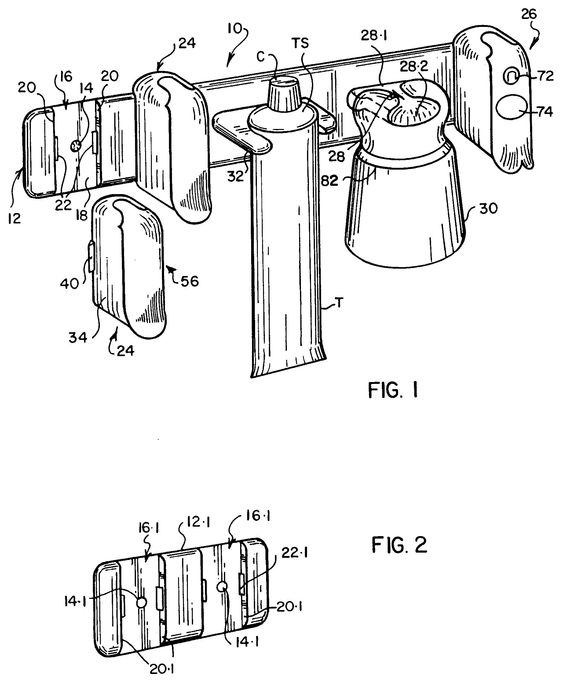
Figure 1 is a pictorial view of a wall mounted structure which incorporates dental
care items;
Figure 2 illustrates a modification of the structure of Figure 1;
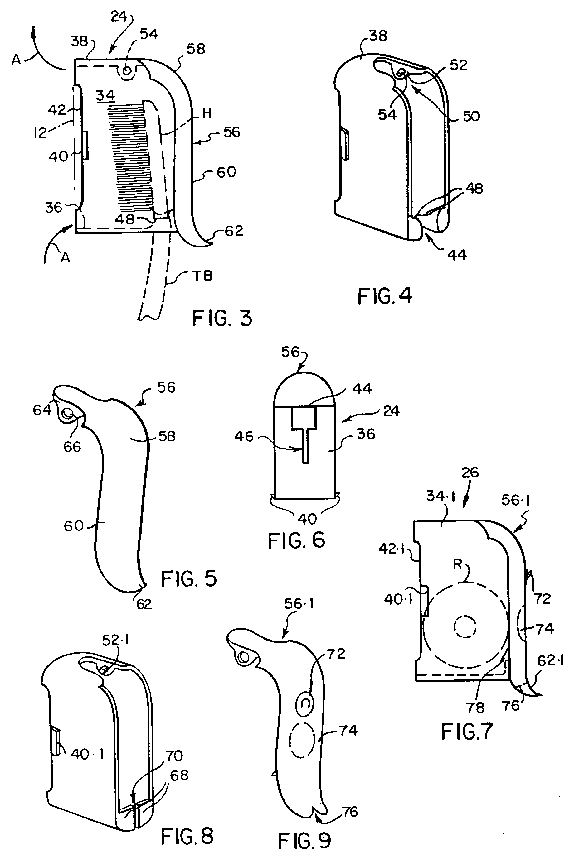
Figure 3 is a side elevation of an enclosure for the head of a toothbrush;
Figure 4 is a pictorial view of the enclosure of Figure 3 without its door;
Figure 5 is a pictorial view of a door;
Figure 6 is an underneath view of the enclosure of Figure 3;
Figure 7 is a side elevation of a dental floss enclosure;
Figure 8 illustrates the enclosure of Figure 7 without its door; and
Figure 9 illustrates the door of the enclosure of Figure 7.
DETAILED DESCRIPTION OF DRAWINGS
[0014] Referring firstly to Figure 1, the structure illustrated is generally designated
10, and comprises a plate 12 which is horizontally elongate and which can be secured
to a wall by screws passed through two screw holes 14, only one of which is visible
in Figure 1. The plate 12 can alternatively be mounted on a wall by means of double-sided
adhesive tape.
[0015] A vertically extending recess 16 extends from the top edge of the plate 12 to the
bottom edge and is bounded by a rear face 18 and two opposed side faces 20. Sockets
22 are provided in the bounding faces 20 of the recess 16.
[0016] Two toothbrush head enclosures 24 are shown in Figure 1. The right hand enclosure
24 is shown attached to the plate 12 and the left hand enclosure 24 is shown detached
from the plate 12. Behind the right hand enclosure 24 there is a second recess 16
which is completely concealed by the enclosure 24. A further enclosure 26 is mounted
on the plate 12 and conceals a further recess 16.
[0017] A support bar 28 protrudes from the plate 12 and a cup 30 is hung from the bar 28.
A bifurcated support 32 also protrudes horizontally from the plate 12 and this serves
to support a tube of toothpaste which is designated T.
[0018] In Figure 2 there is illustrated a plate 12.1 which is formed with two recesses 16.1,
the recesses 16.1 of Figure 2 having the same configuration as the recesses 16 of
Figure 1. The plate 12.1 is secured to a wall (not shown) by screws passed through
the holes 14.1. The bounding faces 20.1 of the recesses 16.1 have sockets 22.1 therein.
The plate 12.1 can thus carry two enclosures 24 or one enclosure 24 and one enclosure
26.
[0019] Turning now to Figures 3 to 6, these illustrate an enclosure 24 in detail. The enclosure
24 illustrated comprises a "box" which is open both at the front and at the rear.
The box is bounded by two vertical side walls 34, a bottom wall 36 and a top wall
38. Lugs 40 are provided on the external faces of the side walls 34 immediately adjacent
the free rear edges 42 of the side walls 34. The lugs 40 are compatible in shape with
the sockets 22.
[0020] The bottom wall 36 has a recess 44 (see particularly Figure 6) in the front edge
thereof, the recess 44 being extended rearwardly by a drainage slot 46. The recess
44 and slot 46 pass through the bottom wall 36. On each side of the recess 44 there
is a protrusion 48. The two protrusions 48 form a cradle on which the head H (Figure
3) of a toothbrush TB can be supported. The handle of the toothbrush is in the recess
44.
[0021] It will be understood from a consideration of the way in which the enclosures 24,
26 are illustrated in Figures 1, 4 and 8 that the inside surface of the bottom wall
36 is of concave configuration and thus slopes down from each side to the drainage
slot 46.
[0022] The top wall 38 has a slot 50 therein and on each side of the slot 50 there is a
mount 52. Each mount 52 depends from the top wall 38 and includes a pin 54. The two
pins 54 are co-axial with one another.
[0023] Reference numeral 56 (see particularly Figure 5) designates a door which is in the
form of a flap. The door includes an upper part 58 and a lower part 60, the parts
58 and 60 merging smoothly with one another and the lower end of the part 60 curving
outwardly (see particularly Figure 3) thereby to provide an operating element 62 for
the door. Two brackets 64 depend from the upper part 58 of the door 56, each bracket
64 having a hole 66 therein. The door 56 is mounted on the enclosure 24 by squeezing
the brackets 64 towards one another, inserting the upper part 58 of the door 56 into
the slot 50 so that the pins 54 are aligned with the holes 66, and then releasing
the brackets 64 so that they spring apart thereby interengaging the pins 54 with the
holes 66 and pivotally mounting the door 56.
[0024] The enclosure 24 is mounted on the plate 12 by squeezing the side walls 34 towards
one another. This reduces the distance between the lugs 40. The side walls 34 are
then inserted into the recess 16. When the side walls 34 are subsequently released,
the lugs 40 enter the sockets 22 and thereby releasably mount the enclosure 24 on
the plate 12. As will be seen from Figure 3, the edges 42 of the side walls 34 are
rebated to receive the plate 12. The enclosure 24 extends both above and below the
plate 12. It will be understood that, because the enclosure 24 does not have a back,
there are inlets to the space within the enclosure 24 both above and below the plate
12. The arrows A in Figure 3 indicate the way in which ventilating air can flow into
and out of the enclosure through these inlets.
[0025] By squeezing the side walls 34 together, thereby to withdraw the lugs 40 from the
sockets 22, the enclosure 24 can readily be removed from the plate 12 and washed out.
[0026] Turning now to Figures 7,8 and 9, the enclosure 26 has many features in common with
the enclosure 24. Where applicable, like parts have been designated with like reference
numerals to which the suffix .1 has been added.
[0027] The protrusions 48, the recess 44 and the slot 46 are omitted from the enclosure
26 which consequently has an unapertured bottom wall. Two front wall portions 68 (Figure
8) protrude upwardly from the bottom wall and there is a vertically extending slot
70 between the wall portions 68. On the outer face of the door 56.1 there is a double
edged stainless steel floss cutter 72. Below the floss cutter 72 there is a depressed
area 74.
[0028] The floss cutter 72 preferably comprises two tangs and a disc-like central portion
between the tangs. The door 56.1 has an external depression for receiving said central
portion and two apertures for receiving the tangs. The tangs are pushed through the
apertures and the portions thereof which project from the inside of the door are bent
over to secure the cutter in place.
[0029] If desired one or more additional cups and one or more additional plates each having
a support 28 protruding therefrom can be provided.
[0030] The operating element 62.1 of the door 56.1 has a notch 76 in it. On the rear of
the door 56.1 there is a protrusion 78.
[0031] A reel R of dental floss is inserted into the enclosure 26 whilst the door is held
in its raised position. The floss is unreeled and drawn down into the slot 70 so that
is has a free end outside the enclosure. The door is then closed and the floss pressed
up into the notch 76, taken upwardly across the depressed area 74 and hooked over
the cutter 72.
[0032] The protrusion 78, by engaging with the top edges of the wall portions 68, forms
a latch to hold the door closed. The protrusion 78 spans between the side walls 34.1.
It thus resists any tendency of the door 56.1 to move sideways when dental floss is
being withdrawn and cut.
[0033] Reverting now to Figure 1, it will be noted that the support 32 is dimensioned so
that it grips the flexible part of the toothpaste tube T below the more rigid top
structure TS onto which the cap C is screwed. The distance between the arms of the
support 32 is less than the diameter of the tube T and hence the tube T is always
squeezed somewhat by the arms of the support 32 so that the toothpaste tube T does
not drop through.
[0034] The support 28 has a slightly wider portion 28.1 adjacent the plate 12 and a slightly
narrower portion 28.2 outwardly of the portion 28.1. The cup 30 has, in the base thereof,
a slot for receiving the support 28. The base of the cup 30 includes two claws 80
which curve towards one another, but do not meet, and which bound the slot. The width
of the slot is slightly more than that of the portion 28.2, so that, as the cup is
slid onto the support 28, the portion 28.2 slides through the slot until the cup encounters
the opposed shoulders which exist where the portion 28.1 merges with the portion 28.2.
This limits further movement of the cup towards the plate 12.
[0035] The cup 30 can be slid off the support 28, inverted, and slid back on in an upright
position. The ring 82 is a separate item which is slid onto the cup over the base
and caused to snap into a groove which is moulded into the cup.
1. A tooth brush head enclosure (24) including walling (34, 36, 38) defining a space
for receiving a tooth brush head (H) from which a handle protrudes, the walling comprising
a bottom wall (36) having a front edge and two spaced side walls (34) having front
edges, said edges bounding a front entrance to said space, a recess (44) in said front
edge of said bottom wall allowing passage therethrough of the handle of a tooth brush
the head of which is in said space whereby the handle can hang down below said enclosure;
a door (56) for closing off said entrance, the door having a first position in which
it closes said entrance and a second position in which said entrance is open to enable
a toothbrush head to be placed in said space or removed from said space; a cradle
(48); and a water drainage slot (46) characterised in that the cradle comprises protrusions
extending upwardly from said bottom wall (36) for supporting a tooth brush head which
is within said space in such manner that the bristles of the tooth brush head are
spaced from said bottom wall (36) and in that said water drainage slot forms an extension
of said recess (44), said bottom wall (36) sloping down to said slot (46) to promote
draining of the enclosure.
2. An enclosure according to claim 1, characterised in that said door (56) is in the
form of a flap having its upper end pivotally mounted on said walling (38).
3. An enclosure according to claim 1 or claim 2, in which said enclosure has two side
walls (34), the side walls having free vertically extending rear edges (42), and mounting
means (40) for the enclosure on said side walls adjacent said rear edges.
4. An enclosure according to claim 3 in which said mounting means (40) are protruding
lugs on the external faces of said side walls adjacent said rear edges.
5. The combination of an enclosure according to claim 3 or claim 4 and a wall mounting
plate (12) including a recess (16) into which said enclosure (24) is inserted with
said rear edges (42) leading, vertical bounding faces (20) of said recess including
sockets (22) for receiving said lugs(40) of the enclosure thereby to mount the enclosure
on the plate.
6. The combination according to claim 5 in which said rear edges protrude above and below
said mounting plate (12) so that a top wall (38) of the enclosure is above the plate
and said bottom wall is below the plate there being inlets to the space within the
enclosure 24 both above and below the plate through which venting air (A) can flow
into and out of the enclosure.
7. The combination of claim 5 or 6 and further including a support bar (28) which protrudes
from said plate (12) and a cup (30) having in the base thereof a slot in which said
bar can be inserted to support said cup, the slot and bar being configured so that
the slot can receive the bar both when the cup is inverted, in which case the cup
hangs down from the bar, or with its base lowermost in which case the cup stands up
on the bar.
8. The combination of claim 5, 6, or 7 and further including a toothpaste tube support
(32) protruding from said plate, said support being bifurcated so as to provide a
recess into which a toothpaste tube (T) can be pushed, the tube hanging vertically
from said support.
9. The combination as claimed in any one of claims 5 to 8 and further including a dental
floss enclosure (26) comprising walling defining a space for receiving a reel (R)
of dental floss, the walling bounding a front entrance to said space and including
side walls (34.1) having free vertically extending rear edges, a door in the form
of a flap (56.1) having its upper end pivotally mounted on said walling and having
a notch (76) in its lower edge through which dental floss can be run from the interior
of said enclosure to the exterior, a dental floss cutter (72) on the front of said
door, the cutter being at a level above said notch so that the floss runs upwardly
from said notch to the cutter, a latch (78) at the lower end of the door for holding
the door closed and for resisting sideways movement of the door when dental floss
is pulled against said cutter on the door to cut off a length of loss, a depression
(74) in the outer face of said door between the notch (76) and the cutter (72) whereby
the portion of the floss spanning from the notch to the cutter traverses said depression,
there being mounting means (40.1) on the external faces of said side walls (34.1)
adjacent said rear edges (42.1) for mounting the dental floss enclosure in a recess
(20) of said plate (12).
1. Aufnahmebehälter (24) für den Kopf einer Zahnbürste, umfassend eine Umwandung (34,
36, 38), die einen Raum zur Aufnahme eines Zahnbürstenkopfs (H) definiert, aus dem
ein Griff hervorragt, wobei die Umwandung eine Bodenwand (36) mit einer Vorderkante
und zwei beabstandete Seitenwände (34) mit Vorderkanten umfaßt, wobei die Kanten einen
vorderen Zugang zum Raum begrenzen, wobei eine Ausnehmung (44) in der Vorderkante
der Bodenwand ein Hindurchführen des Griffs einer Zahnbürste zuläßt, deren Kopf sich
im Raum befindet, wodurch der Griff aus dem Behälter nach unten heraushängen kann;
eine Tür (56) zum Verschließen des Zugangs, wobei die Tür eine erste Position, in
der sie den Zugang verschließt, sowie eine zweite Position aufweist, in der der Zugang
offen ist, sodaß ein Zahnbürstenkopf in den Raum eingebracht oder aus dem Raum entnommen
werden kann; ein Hängegestell (48); und einen Wasserablaufschlitz (46), dadurch gekennzeichnet,
daß das Hängegestell Vorsprünge umfaßt, die sich von der Bodenwand (36) nach oben
erstrecken, um einen Zahnbürstenkopf, der sich innerhalb des Raumes befindet, so zu
halten, daß die Borsten des Zahnbürstenkopfs von der Bodenwand (36) beabstandet sind
und daß der Wasserablaufschlitz eine Verlängerung der Ausnehmung (44) bildet, wobei
die Bodenwand (36) zum Schlitz (46) hin abfällt, um das Ablaufen aus dem Aufnahmebehälter
zu unterstützen.
2. Aufnahmebehälter nach Anspruch 1, dadurch gekennzeichnet, daß die Tür (56) die Form
einer Klappe aufweist, deren oberes Ende verschwenkbar an der Umwandung (38) montiert
ist.
3. Aufnahmebehälter nach Anspruch 1 oder 2, worin der Aufnahmebehälter zwei Seitenwände
(34) aufweist, wobei die Seitenwände freie, sich vertikal erstreckende Hinterkanten
(42) aufweisen, sowie an den Seitenwänden angrenzend an die Hinterkanten vorgesehene
Montagemittel (40) für den Aufnahmebehälter.
4. Aufnahmebehälter nach Anspruch 3, worin die Montagemittel (40) an die Hinterkanten
angrenzende, vorstehende Ansätze an den Außenflächen der Seitenwände sind.
5. Kombination aus einem Aufnahmebehälter nach Anspruch 3 oder 4 und einer Wandmontageplatte
(12), die eine Ausnehmung (16) umfaßt, in die der Aufnahmebehälter (24) mit den Hinterkanten
(42) voraus eingesteckt ist, wobei vertikale Begrenzungsflächen (20) der Ausnehmung
Sockel (22) zum Aufnehmen der Ansätze (40) des Aufnahmebehälters umfassen, um dadurch
den Aufnahmebehälter an der Platte zu montieren.
6. Kombination nach Anspruch 5, worin die Hinterkanten oberhalb und unterhalb der Montageplatte
(12) vorstehen, sodaß eine obere Wand (38) des Aufnahmebehälters sich oberhalb der
Platte und die Bodenwand sich unter der Platte befindet, wobei sich sowohl oberhalb
als auch unterhalb der Platte Einlässe in den Raum innerhalb des Aufnahmebehälters
(24) befinden, durch die Belüftungsluft (A) in den Aufnahmebehälter hinein und aus
diesem heraus strömen kann.
7. Kombination nach Anspruch 5 oder 6, die weiters eine Haltestange (28), die aus der
Platte (12) herausragt, sowie einen Becher (30) umfaßt, an dessen Basis sich ein Schlitz
befindet, in den die Stange eingeschoben werden kann, um den Becher zu halten, wobei
der Schlitz und die Stange so geformt sind, daß der Schlitz die Stange sowohl aufnehmen
kann, wenn der Becher umgedreht ist, in welchem Fall der Becher von der Stange nach
unten herabhängt, als auch dann, wenn sein Boden den untersten Teil bildet, in welchem
Fall der Becher aufrecht auf der Stange steht.
8. Kombination nach Anspruch 5, 6 oder 7, die weiters eine Zahnpastatubenhalterung (32) umfaßt, die aus der Platte herausragt,
wobei die Halterung gegabelt ist, sodaß sie eine Ausnehmung bildet, in die eine Zahnpastatube
(T) gedrückt werden kann, wobei die Tube vertikal von der Halterung herabhängt.
9. Kombination nach einem der Ansprüche 5 bis 8, die weiters einen Zahnseidenaufnahmebehälter
(26) umfaßt, der eine Umwandung, die einen Raum zur Aufnahme einer Zahnseidenspule
(R) definiert, wobei die Umwandung einen vorderen Zugang zum Raum begrenzt und Seitenwände
(34.1) mit freien, sich vertikal erstreckenden Hinterkanten umfaßt; eine Tür in Form
einer Klappe (56.1), deren oberes Ende schwenkbar an der Umwandung montiert ist und
die eine Kerbe (76) in ihrer unteren Kante aufweist, durch die Zahnseide aus dem Inneren
des Aufnahmebehälters nach außen geführt werden kann; einen Zahnseidenschneider (72)
an der Vorderseite der Tür, wobei sich der Schneider in einer Höhe oberhalb der Kerbe
befindet, sodaß die Seide von der Kerbe zum Schneider nach oben läuft; einen Riegel
(78) am unteren Ende der Tür, um die Tür geschlossen zu halten und einer Seitwärtsbewegung
der Tür entgegenzuwirken, wenn Zahnseide gegen den an der Tür befindlichen Schneider
gezogen wird, um ein Stück Zahnseide abzuschneiden; und eine Vertiefung (74) in der
Außenfläche der Tür zwischen der Kerbe (76) und dem Schneider (72) umfaßt, wodurch
jener Abschnitt der Zahnseide, der sich von der Kerbe zum Schneider erstreckt, quer
über die Vertiefung verläuft, wobei Montagemittel (40.1) an den Außenflächen der Seitenwände
(34.1) angrenzend an die Hinterkanten (42.1) montiert sind, um den Zahnseidenaufnahmebehälter
in einer Ausnehmung (20) der Platte (12) zu montieren.
1. Boîtier (24) pour tête de brosse à dents comprenant des parois (34, 36, 38) définissant
un espace pour recevoir une tête de brosse à dents (H) à partir de laquelle fait saillie
une poignée, les parois comprenant une paroi de fond (36) ayant un bord frontal et
deux parois latérales espacées (34) ayant des bords frontaux, lesdits bords délimitant
une entrée frontale dudit espace, un creux (44) dans ledit bord frontal de ladite
paroi de fond permettant le passage à travers celle-ci de la poignée d'une brosse
à dents dont la tête est dans ledit espace de sorte que la poignée peut pendre sous
ledit boîtier; une porte (56) pour fermer ladite entrée, la porte ayant une première
position dans laquelle elle ferme ladite entrée et une seconde position dans laquelle
ladite entrée est ouverte pour permettre de placer une tête de brosse à dents dans
ledit espace ou de la retirer dudit espace; un berceau (48); et une fente d'écoulement
d'eau (46), caractérisé en ce que le berceau comprend des saillies s'étendant vers
le haut à partir de ladite paroi de fond (36) pour supporter une tête de brosse à
dents qui est dans ledit espace d'une manière telle que les poils de la tête de brosse
à dents sont espacés de ladite paroi de fond (36) et en ce que ladite fente d'écoulement
d'eau forme une extension dudit creux (44), ladite paroi de fond (36) s'inclinant
vers le bas vers ladite fente (46) pour favoriser le drainage du boîtier.
2. Boîtier selon la revendication 1, caractérisé en ce que ladite porte (56) a la forme
d'un volet ayant son extrémité supérieure montée pivotante sur lesdites parois (38).
3. Boîtier selon la revendication 1 ou 2, dans lequel ledit boîtier comporte deux parois
latérales (34), les parois latérales ayant des bords libres postérieurs s'étendant
verticalement (42), et des moyens de montage (40) pour le boîtier sur lesdites parois
latérales adjacents auxdits bords postérieurs.
4. Boîtier selon la revendication 3, dans lequel lesdits moyens de montage (40) sont
des pattes saillantes sur les races externes desdites parois latérales adjacentes
auxdits bords postérieurs.
5. Combinaison d'un boîtier selon la revendication 3 ou 4 et d'une plaque de montage
de paroi (12) comprenant un renfoncement (16) dans lequel ledit boîtier (24) est inséré
avec lesdits bords postérieurs (42) en tête, des faces verticales de retenue (20)
dudit renfoncement comprenant des mortaises (22) pour recevoir lesdites pattes (40)
du boîtier afin de monter le boîtier sur la plaque.
6. Combinaison selon la revendication 5, dans laquelle lesdits bords postérieurs font
saillie au-dessus et en dessous de ladite plaque de montage (12) de façon qu'une paroi
supérieure (38) du boîtier soit au-dessus de la plaque et ladite paroi de fond soit
en dessous de la plaque, des orifices d'admission dans l'espace étant prévus dans
le boîtier (24) à la fois au-dessus et on dessous de la plaque à travers lesquels
de l'air de ventilation (A) peut circuler dans le boîtier et hors de celui-ci.
7. Combinaison selon la revendication 5 ou 6, et comprenant en outre une barre de support
(28) qui fait saillie de ladite plaque (12) et un gobelet (30) ayant dans sa base
une fente dans laquelle ladite barre peut être insérée pour supporter ledit gobelet,
la fente et la barre étant configurées de façon que la fente puisse recevoir la barre
à la fois lorsque le gobelet est inversé, dans lequel cas le gobelet pend vers le
bas à partir de la barre, ou avec sa base extrême inférieure dans lequel cas le gobelet
repose verticalement sur la barre.
8. Combinaison selon l'une des revendications 5 à 7, et comprenant en outre un support
(32) de tube de pâte dentifrice faisant saillie de ladite plaque, ledit support étant
en fourche pour réaliser un creux dans lequel un tube de pâte dentifrice (T) peut
être poussé, le tube étant suspendu verticalement à partir dudit support.
9. Combinaison selon l'une des revendications 5 à 8, et comprenant en outre un boîtier
(26) pour du fil dentaire comprenant des parois définissant un espace pour recevoir
une bobine (R) de fil dentaire, les parois délimitant une entrée frontale dudit espace
et comprenant des parois latérales (34.1) ayant des bords libres postérieurs s'étendant
verticalement, une porte sous la forme d'un volet (56.1) ayant son extrémité supérieure
montée pivotante sur lesdites parois et ayant une encoche (76) dans son bord inférieur
à travers lequel le fil dentaire peut défiler de l'intérieur dudit boîtier vers l'extérieur,
un coupoir de fil dentaire (72) sur la façade de ladite porte, le coupoir étant à
un niveau au-dessus de ladite encoche de façon que le fil se déplace vers le haut
à partir de ladite encoche vers le coupoir, un verrou (78) à l'extrémité inférieure
de la porte pour tenir la porte fermée et pour résister à des mouvements latéraux
de la porte lorsque le fil dentaire est tiré contre ladit coupoir sur la porte pour
couper une longueur de fil, un évidement (74) dans la face externe de ladite porte
entre l'encoche (76) et le coupoir (72) de façon que la portion du fil s'étendant
entre l'encoche et le coupoir traverse ledit évidement, des moyens de montage (40.1)
étant prévus sur les faces externes desdites parois latérales (34.1) adjacents auxdits
bords postérieurs (42.1) pour monter le boîtier de fil dentaire dans un renfoncement
(20) de ladite plaque (12).