| (19) |
 |
|
(11) |
EP 0 531 247 A1 |
| (12) |
EUROPEAN PATENT APPLICATION |
| (43) |
Date of publication: |
|
10.03.1993 Bulletin 1993/10 |
| (22) |
Date of filing: 04.09.1992 |
|
|
| (84) |
Designated Contracting States: |
|
BE CH DE ES FR GB IT LI NL SE |
| (30) |
Priority: |
04.09.1991 DK 1552/91
|
| (71) |
Applicant: LINAK A/S |
|
DK-6430 Nordborg (DK) |
|
| (72) |
Inventor: |
|
- Jensen, Bent
DK-6430 Nordborg (DK)
|
| (74) |
Representative: Pedersen, Soeren Skovgaard |
|
c/o K. Skoett-Jensen Patentingenioerer A/S,
Lemmingvej 225
8361 Hasselager
8361 Hasselager (DK) |
|
| |
|
(57) In linear actuators, where the spindle device (6) is driven via a toothed gearing
comprising two bevel gears (10, 12), it proves difficult to maintain a satisfactory
greasing of the two gears. The grease is "cut" off the gears relatively soon. The
solution to this problem is to completely contain the gears inside their respective,
separate chambers between tightly limiting surfaces, at least at the gear rim area,
such that the grease be retained in this area and be forcibly applied on the gear
rim to effect the greasing.
|

|
[0001] The invention relates to a linear actuator comprising a spindle device driven via
a toothed gearing having two bevel gears, where the transmission shaft is engaging
one gear and the spindle the other one.
[0002] It proves difficult in a simple manner to ensure greasing the gears. The gears have
been greased from the factory with an antinoise grease, but this tends to be "cut"
off the gears at a relatively early stage, resulting in metal grinding against metal
and the gears consequently soon be worn down. The heavier the loads that the actuators
be subject to, the sooner the shearing of the grease takes place and that at a time
when greasing is most vital. Furthermore the centrifugal force itself causes the grease
to be thrown off the gears, and the gravitational force likewise tends to make the
grease run off.
[0003] The object of the invention was simply to find a constructively simple and inexpensive
solution to ensure greasing of the gears during the entire service life of the actuator,
including it being subject to heavy loads. This is achieved by a solution according
to the invention where the gears at least at the gear rim area are fully contained
inside their individual chambers between snuggly limiting surfaces such that the grease
be retained in this area and be carried along on the gear rim, this being the correct
place for performing said application of grease. The grease is so to speak forcibly
supplied from one gear to the other where these are entering into engagement with
one another. By applying grease of an antinoise nature the actuator will consequently
retain a low noise level all its service life, this being of significance. Field experiments
have proved that a construction according to the invention offers a service life of
twice the usual for the gears. Further features of the invention are disclosed in
the subsequent claims.
[0004] The actuator according to the invention will be described in further detail in the
following with reference to the attached drawing illustrating an embodiment. The drawing
illustrates as follows:-
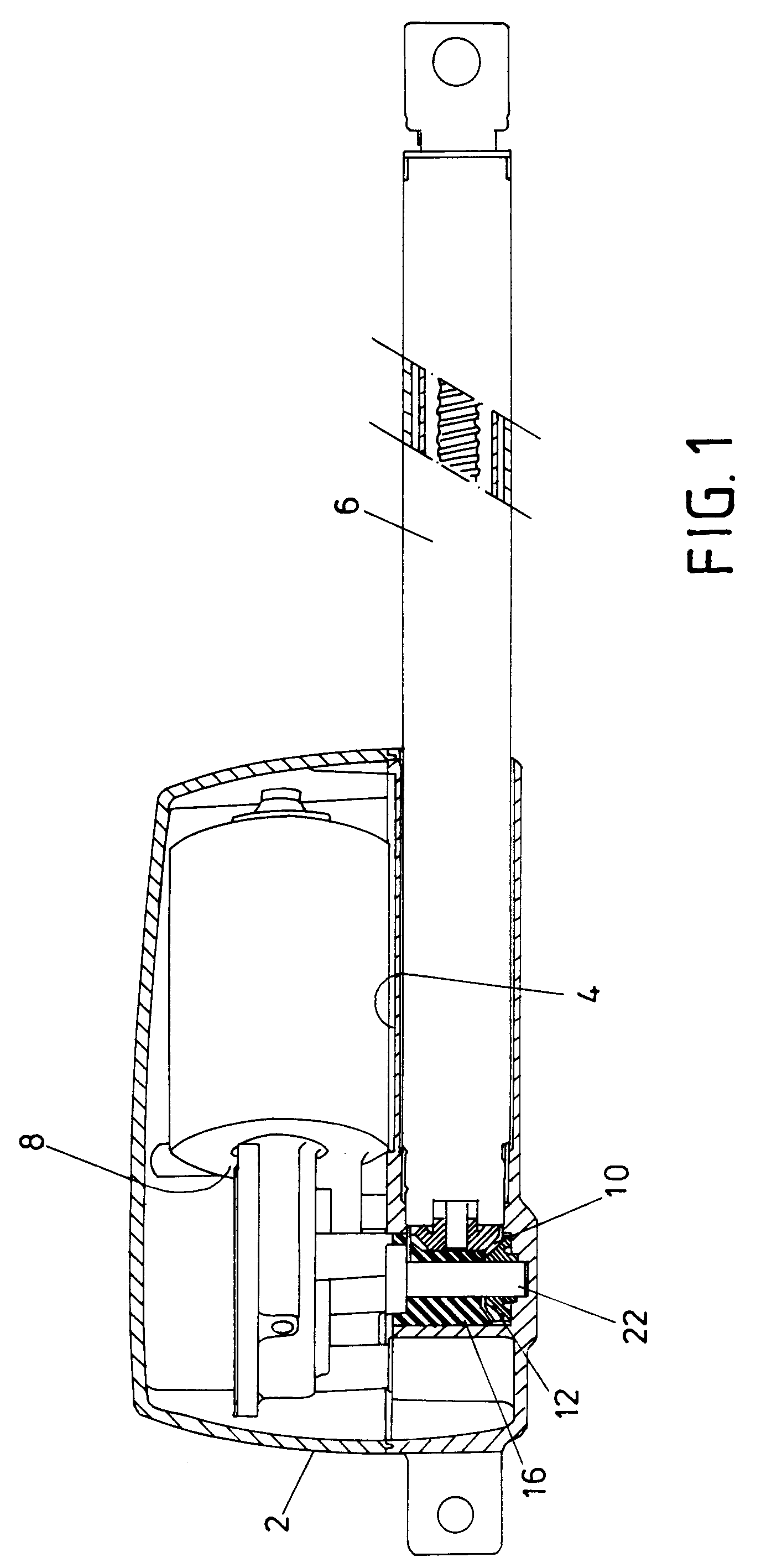
Fig. 1 illustrates a longitudinal section through the actuator,
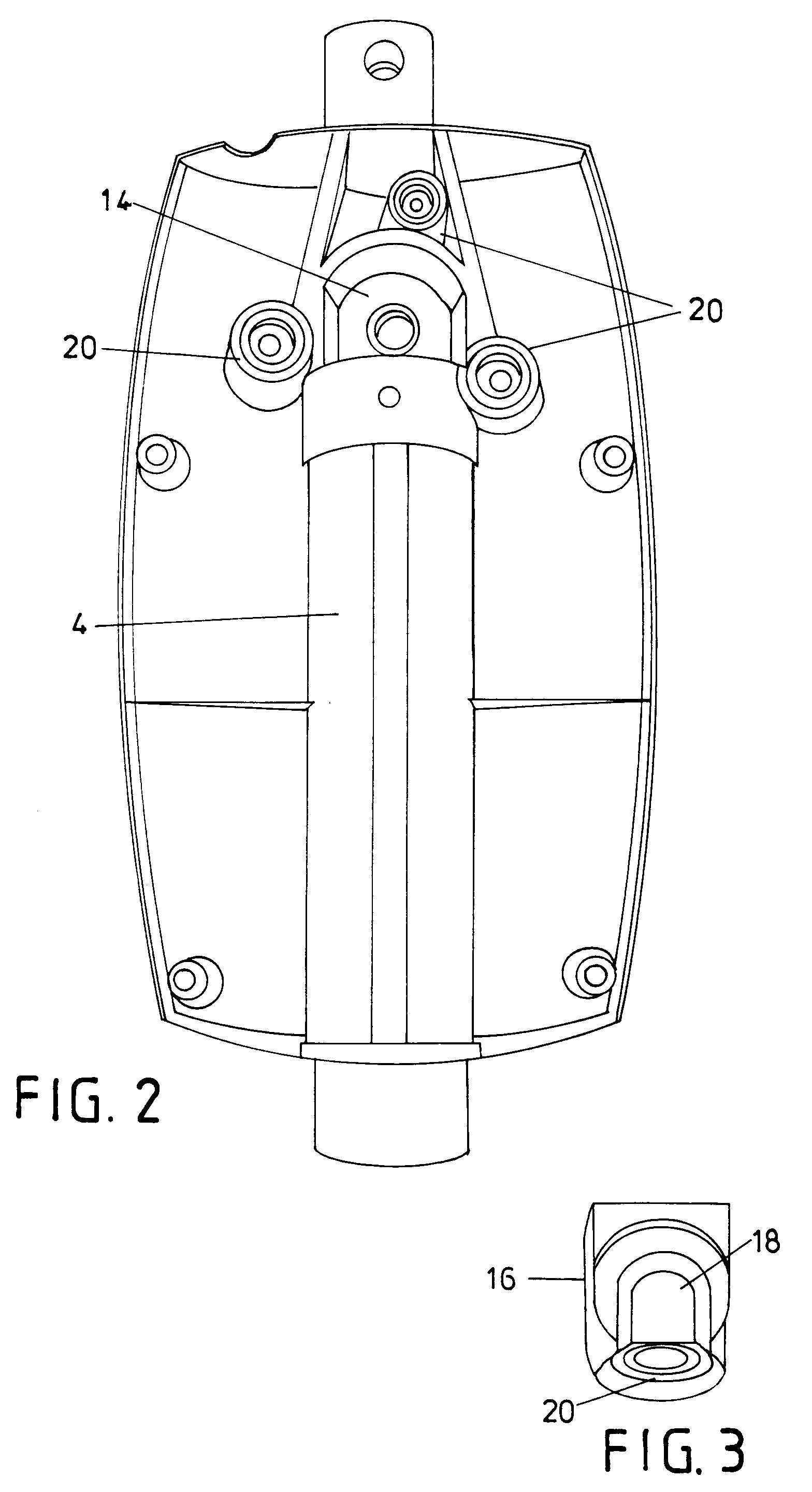
Fig. 2 illustrates the lower portion of the actuator casing seen from above, and
Fig. 3 is a perspective view from beneath of the infilling element.
[0005] The actuator comprises a casing 2 consisting of a lower and an upper portion having
an internal tube-formed portion 4 in the lower portion in which a spindle device 6
is embedded. The upper portion of the casing accommodates an electric motor 8 integral
with a mitre gear for driving the spindle via a toothed gearing consisting of two
bevel gears 10, 12. The bevel gear 10 of the spindle device, i.e. the gear at the
end of the actual spindle is attached to and protrudes from the end of the tube-formed
portion 4 and the bevel gear 12 of the transmission shaft, i.e. the gear at the end
of the transmission shaft 22 of the transmission unit is in engagement with the former
at the lower side. The gears are contained inside a compartment 14, where the shape
of the bottom corresponds to the lower side of the toothed gear. The lateral limits
of the compartment are constituted of the tube-formed portion 4 containing the spindle
device, and opposite to this a semicircular wall narrowly encircling the circumference
of the transmission shaft gear as well as a straight section of wall at either side
continuing the curved wall as tangents to connection to the end of the tube-formed
portion of the spindle device. Inside the compartment is detachably inserted an infilling
element 16, the lower end of which has a shape that corresponds to the upper side
of the transmission gear, and the flat side of said element facing towards the spindle
device having a shape that corresponds to the shape of the spindle gear. The gears
are thus contained inside their separate chambers 18, 20 having the surfaces tightly
against the gear rims such that the grease is retained on the rims eliminating any
possibility of shearing the grease even in cases of heavy loads. The infilling element
16 has a recess to accommodate the transmission shaft 22. The element is detachably
placed down into the compartment and is retained in position by the motor unit that
is being supported by the compartment wall and has screws securing it to the three
pillars 24 in the lower portion. The element 16 consequently also retains the gears
in their positions.
[0006] It should be realized that the above only serves as an example of an embodiment and
that the invention as specified in the following claims can have a variety of actual
embodiments.
1. A linear actuator comprising a spindle device (6) driven via a toothed gearing (10,
12) where the transmission shaft (22) be in engagement with one bevel gear (12) and
the spindle (6) with the other bevel gear (10), characterized in that the bevel gears
at least in the gear rim area are totally contained inside their respective, separate
chambers (18, 20), where the walls are in intimate contact with the gears, and where
the chambers exclusively are in connection with one another via the mutual engagement
of the two gears, whereby the grease is retained on the gears and forcibly applied
with these, during running.
2. An actuator according to claim 1, characterized in that the chambers (18, 20) for
the gears are designed in a separate element (16) coupled to the actuator casing (2).
3. An actuator according to claim 2, characterized in that the limit of one chamber (18)
is constructed in a planar lateral face of the separate element (16) and that the
limit of the other chamber (20) is constructed in an end face of the separate element.
4. An actuator according to claim 3, characterized in that a compartment (14) is constructed
in the actuator for accommodating the separate element (16) where the support face
of the bevel gear (10) of the spindle constitutes part of the lateral wall of the
compartment and where the support face for the driven bevel gear (12) constitutes
part of the floor or ceiling of the compartment.
5. An actuator according to claim 4, characterized in that the support face for the bevel
gear (10) of the spindle is constituted of the end of the tube-formed portion (4)
of the spindle device and that the lateral wall of the compartment from there encircles
the driven bevel gear (12) in intimate contact with its circumference, and that a
continuous recess for the transmission shaft (22) is incorporated in the element (16).
6. An actuator according to claim 5, characterized in that the height of the element
(16) is adapted to reaching the upper edge of the compartment (14) and is retained
by the electric motor (8) being mounted above the compartment.