|
(11) | EP 0 597 974 B1 |

| (12) | EUROPEAN PATENT SPECIFICATION |
|
|
| (54) |
METHOD FOR SMOOTHING OUT ACCELERATION JERKS OF A VEHICLE PROPELLED BY AN INTERNAL-COMBUSTION ENGINE Verfahren zur Glättung von Beschleunigungsstösse eines durch eine Brennkraftmaschine angetriebenen Fahrzeugs PROCEDE D'AMORTISSEMENT DES A-COUPS A L'ACCELERATION DANS UN VEHICULE MU PAR UN MOTEUR A EXPLOSION |
|
|
|||||||||||||||||||||||||||||||
| Note: Within nine months from the publication of the mention of the grant of the European patent, any person may give notice to the European Patent Office of opposition to the European patent granted. Notice of opposition shall be filed in a written reasoned statement. It shall not be deemed to have been filed until the opposition fee has been paid. (Art. 99(1) European Patent Convention). |
[0001] The present invention relates to a method for smoothing out acceleration jerks of a motor vehicle propelled by an internal-combustion engine and, more particularly, to such a method enabling such jerks to be smoothed out in an acceleration phase from a steady state or after a deceleration phase.
[0002] Figure 5B of the attached drawing shows the variation with time of various parameters connected with the engine or with the vehicle, following an abrupt acceleration requested by the driver at the instant to. At this instant, the driver presses the accelerator pedal right down which controls the opening of the throttle valve. Since the ignition-advance angle A of the engine is conventionally corrected in order to provide a maximum torque, the longitudinal acceleration of the vehicle is recorded with the aid of an accelerometer. On the recording of the output signal from this accelerometer, time oscillations of a substantial amplitude which are progressively damped are observed. These oscillations represent jerks which are disagreeably experienced by the driver. Thus it may be said that the level of driving comfort of the vehicle is lowered by these jerks.
[0003] The recorded oscillations of the acceleration arise from the "elasticity" of the kinematic system which goes from the engine to the wheels of the vehicle, in particular at the clutch disc and at the cardan joints. Too rapid an increase in the engine torque, requested by the driver during an acceleration, causes the system to oscillate, the oscillations produced being manifested for the driver by disagreeable jerks in the progression of the vehicle.
[0004] Ways have been sought to eliminate these jerks by controlling the engine torque at the start of acceleration. According to a first Solution explained in French Patent Application FR-A-2 633 978 filed in the name of BENDIX ELECTRONICS, the action of the accelerator pedal is neutralised over the angle of opening of the throttle valve in an initial zone of the travel of this pedal and the flow rate of air inducted into the engine is then regulated with the aid of a particular control law, in order to avoid jerks, but only in the case of low charges.
[0005] According to another solution described in French Patent Application EP-A-517838 in the name of SIEMENS AUTOMOTIVE S.A., the masses of air and of fuel entering the engine are controlled so as to constrain the latter to follow a behaviour defined by a model. It is then possible to optimise the response of the engine, including when transient accelerations are requested by the driver.
[0006] These solutions, which require the use of a throttle valve actuated by a motor, thus have the drawback of being expensive.
[0007] This drawback is overcome by the method for transient-state correction of the ignition advance of an internal-combustion engine described in French Patent Application FR-A-2 678 986 filed on 9th July 1991 by the Applicant. According to this method, on changing the gear ratio of a gearbox associated with the engine, jerks in the speed of this engine on reaccelerating are eliminated by correcting the ignition advance as a function of the time derivative of the induction pressure of the engine, substantially until leaving the transient state due to the gear-ratio change. The reacceleration is detected by the increase in the pressure at the induction manifold of the engine which results therefrom.
[0008] Although this method has given satisfactory results, there is still a need for a method for smoothing out the jerks which is based on a solid theoretical basis, enabling the method to be optimised.
[0009] EP-A-339 602 and US-A-4 799 469 disclose methods for smoothing out acceleration jerks, wherein an acceleration phase of the engine is detected and the ignition advance is reduced in dependence of the selected gear ratio.
[0010] The object of the present invention is therefore to provide a method for smoothing out acceleration jerks which is inexpensive to implement and may be applied to various situations in which an acceleration requested by the driver is liable to cause the jerks which lower the level of driving comfort of the vehicle.
[0011] The object of the present invention is also to provide such a method which is sustained by a theoreticai basis allowing the process to be optimised.
[0012] These objectives of the invention are achieved, as well as others which will emerge on reading the description which follows, with a method for smoothing out acceleration jerks of a motor vehicle propelled by an internal-combustion engine, a method according to which an entry into an acceleration phase of the vehicle is detected, the ignition advance of the engine is then reduced to a predetermined value and the advance is maintained at this value for a predetermined time interval which is a function of the selected gear ratio of a gearbox placed on the output side of the engine.
[0013] As will be seen below, by adopting such a method for controlling the ignition advance during a transient acceleration phase, the amplitude of the jerks mentioned hereinabove is considerably reduced, it being possible to reduce this amplitude to 20% of the amplitude observed without the application of the present invention. As a result there is a great improvement in the driving comfort.
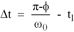
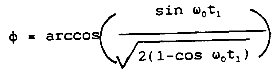
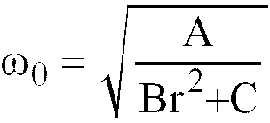
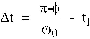
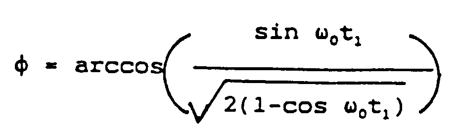
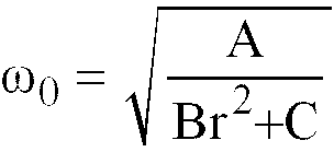
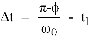
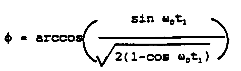
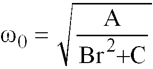
[0014] According to a preferred implementation of the method according to the invention, the time interval Δt is of the form:
where:
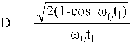
characteristic frequency of the system,
A, B, C are constants,
t1 = duration of the acceleration requested by the driver.
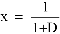
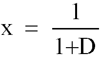
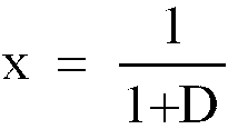
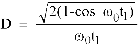
[0015] Still according to the invention, a reduction ratio x in the torque delivered by the engine is calculated which is suitable for smoothing out the jerks, such that:
with
and then the ignition-advance reduction, to be put into operation in order to obtain the reduced torque, is calculated.
[0016] Other characteristics and advantages of the method according to the invention will emerge on reading the description which follows and on examining the attached drawing in which:
- Figures 1 and 2 are diagrams which illustrate a modelling according to the invention of the kinematic system which goes from an internal-combustion engine to the wheels of the vehicle which it propels,
- Figure 3 is a graph, useful for the explanation of the method according to the invention, of absorption of the jerks observed in an acceleration phase of the vehicle,
- Figure 4 is a time diagram which illustrates the change with time of the value of the ignition-advance change with time of the value of the ignition-advance angle of the engine, established by the present invention, during an acceleration phase of the vehicle and
- Figures 5A and 5B are sets of time diagrams of the change with time of the value of the ignition advance, from the output of a longitudinal accelerometer and from the output of an opening-angle sensor of a throttle valve of the engine, which serve to illustrate the improvement in the driving comfort obtained by the present invention.
[0017] According to the invention, in order to reduce the aforementioned oscillations, reliance is placed on a prior modelling of the kinematic system in question. This modelling leads to the diagram in Figure 1 where the engine takes the form of a mass of inertia J representing the inertia of the connecting-rod assembly and of the flywheel of the engine. The latter is conventionally associated with a clutch whose characteristics are similar to those of a spring of stiffness K1. The clutch itself is associated with a gearbox whose inertia may be considered as small with respect to that of the engine and which therefore may be neglected, together with possible angular backlash. In the model in Figure 1, the gearbox is represented by the speed-reducing gear ratio r. The members for transmitting the power to the wheels of the vehicle may be modelled by a spring of stiffness K2. The kinematic system is excited by a torque C developed by the engine.
[0018] The model shown schematically in Figure 1 may be simplified and reduced to the elements appearing in Figure 2 where the model comprises only a mass of inertia J and a spring of stiffness K such that:
[0019] It will be noted from now on that the equivalent stiffness K is a function of the selected gear ratio r of the gearbox.
[0020] The dynamic behaviour of the system, constituted by the mass of inertia J and the spring of stiffness K tial equation:
where θ is an angle which defines the angular position of the flywheel of the engine. It is the time fluctuations or oscillations in the value of this angle, which are induced by an abrupt increase in the engine torque requested by the driver, which are the cause of the jerks experienced by said driver during an acceleration phase.
[0021] According to the present invention, it is possible to cancel or at least reduce these oscillations, by controlling the engine torque during an acceleration phase as illustrated in Figure 3. In this figure are represented the oscillations θA which are conventionally observed when the engine torque passes linearly from the value C0 to the value C1, following an action of the driver on the accelerator pedal, which controls an increase in the opening angle of a throttle valve of the engine during a time t1 called hereinafter "acceleration time". Wide oscillations in θA are then observed which may lead to appreciable variations, of the order of 0.3 g, in the acceleration of the vehicle. It is these variations which the invention aims to reduce.
[0022] In order to do this, the torque developed by the engine is limited at will, by substituting that requested by the driver with that (CL) controlled according to the invention after a linear rise in the torque until the instant t1, estimated beforehand, and the torque is stabilised at the value CL for a time Δt, this value corresponding to a predetermined fraction of the final torque C1 requested by the driver, the end of the time interval Δt coinciding with a first maximum of the oscillation in the angle θA, reached at the instant t2. The variations with time of the angle θ are then constrained as represented in Figure 3, any oscillation even being theoretically stifled after t2, which considerably improves the driving comfort.
[0023] This limitation of the torque to the value CL is obtained according to the invention by a reduction in the ignition advance of the engine. It is known that such a reduction, with respect to a value giving the optimum torque, enables the torque supplied to be reduced. It is also known that, conventionally, this advance is measured in degrees of angle before a piston of the engine passes through its top dead centre (TDC).
[0024] According to an essential characteristic of the method according to the invention, the duration Δt during which it is required to reduce the ignition advance in order to stabilise the torque at the value CL, depends on the selected gear ratio r in the gearbox. According to the invention, Δt is calculated with the aid of the following formula:
with
and
characteristic frequency of the system
A, B, C being constants such that:
A = K1.K2
B = J.K1
C = J.K2
[0025] It should be noted that Δt, being a function of the characteristic frequency ω0 of the system, is ultimately a function of the gear ratio r since ω0 is a function of r.
[0026] Having thus calculated the duration Δt of the advance reduction, it is still necessary to determine the limiting torque C1 to be maintained for Δt. Assuming that the maximum torque C1 is fixed, a reduction ratio (x) in this torque C1 is sought such that:
with
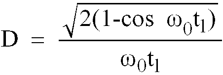
D corresponding to an "overshoot rate" of the oscillations of the system.
[0027] Thus x is in fact a function of the selected gear ratio of the gearbox, being a function of ω0 which depends on r.
[0028] The method according to the invention is designed to be implemented in a system where the engine is controlled by an ignition and, optionally, injection computer. Such a computer conventionally comprises one or more microprocessors which may by duly programmed in order to execute the calculations indicated hereinabove. The implementation of the method according to the invention also requires the computer to receive the output from an accelerator-pedal position sensor and, at least, from such a sensor which is sensitive to the "foot up-foot down" transition, which is generally the case. Provision must also be made for a sensor providing the computer with the "r" information, that is to say the gear ratio engaged in the gearbox. Such sensors commonly equip gearboxes in order to provide the r information to a computer.
[0029] A potentiometric throttle-valve position sensor is also commonly used to supply a signal to an ignition-and injection-control computer. According to the invention, when the time derivative of the signal supplied by the sensor, which derivative is calculated by the computer, exceeds a predetermined threshold, the overshoot is interpreted as resulting from an abrupt acceleration requested by the driver, from a steady state for example. The advance correction according to the invention is then activated.
[0030] Reference is now made to the graph in Figure 4 in order to describe more completely the change with time of the ignition-advance angle established on executing the method according to the invention, during an acceleration phase of the engine. Starting from an instant t0 when the driver of the vehicle presses on the accelerator pedal in order to request an acceleration, the control of the ignition-advance angle by the ignition computer associated with the engine, conventionally operated as a function of the speed of this engine and of the air-induction pressure or of the inducted-air flow rate, is inhibited and replaced by the control according to the present invention. According to a preferred form of implementing this control, the advance angle is first of all uniformly decremented to a value aL corresponding to the torque reduction sought by the invention, this advance being maintained for the time interval Δt. The latter is normally close to 0 as represented in Figure 4. At the end of the time interval Δt which is a function, according to the invention, of the gearbox gear ratio r, the ignition-advance angle is rapidly incremented until the moment when the advance thus incremented exceeds the advance normally calculated by the ignition computer which then reassumes the control of the ignition-advance angle. The invention thus relates to the control of the ignition-advance angle during a transient acceleration phase, which control is substituted, only during such phases, by the control developed by the computer according to conventional rules. This substitution enables the acceleration jerks, which the driver would normally experience if the computer continued to operate conventionally during the acceleration phases, to be eliminated or greatly limited.
[0031] According to a preferred form of implementing the present invention, in order to avoid appreciable jerks caused by an advance reduction operated at low speed, the ignition-advance angle control according to the invention is only used, in an acceleration phase, if the speed of the engine is greater than a predetermined speed, 700 rpm for example. A speed sensor commonly feeds information to ignition-advance computers which renders the implementation of this arrangement particularly simple.
[0032] In some computers, the ignition advance is calculated as a function of the speed of the engine and of the pressure or of the inducted-air flow rate. The locating in time of the events arising during one cycle of the engine is then produced with signals which are a function of the speed. It is then clear that the time Δt for maintaining the reduced advance aL will be, in this case, a function not only of the gearbox gear ratio r but also of the speed of the engine.
[0033] The ignition-advance reduction according to the invention is effective for relatively abrupt accelerations, of a duration t1 of between approximately 0.1 and 0.3 s. For accelerations of longer duration, the aforementioned jerks are less appreciable and the correction is no longer necessary.
[0034] The amplitude of the oscillations to be eliminated is proportional to the increase in the opening angle of the valve during the acceleration time t1. Thus, if the advance correction according to the invention is effective for an increase in a given opening of the valve, this is also the case for a smaller valve opening even if, in this case, the torque limitation put into operation is greater than necessary.
[0035] According to the theoretical model established as indicated hereinabove, the amplitude of the oscillations diminishes when the gearbox gear ratio r increases, for a same acceleration time t1. However, it will be noted that the advance back-off according to the invention remains necessary at high gear ratios since, the average acceleration being lower at these gear ratios, the driver experiences the acceleration oscillations to the same degree.
[0036] The advance back-off according to the invention, illustrated by Figure 4, reveals that this back-off can vary as a function of various parameters: rate of decrease in the advance angle, value of the reduced advance aL, duration Δt of this advance, rate of rise in the advance. These parameters are influenced by a possible injection cut-off of fuel, in a deceleration phase prior to a reacceleration requested by the driver. The programming of the calculations into the microprocessor of the computer is then provided so as to take into account a possible injection cut-off, known from the computer which also controls the opening of the injectors and the injection time, within the value of these parameters.
[0037] As has been seen above, in computers where the rates of events are determined by a signal whose frequency is a function of the speed of the engine, the time Δt, for maintaining the reduced torque aL, expressed as the number of times the piston of a cylinder passes through the top dead centre, will have to be corrected as a function of the speed, as well as the rates of decrease and of rise of the advance. On the other hand, since the speed has no influence on the overshoot rate D of the oscillations of the system occurring in the expression for the reduction ratio x, this amount of reduction is not influenced by the speed.
[0038] Reference will now be made to Figures 5A and 5B which represent the change in time of the ignition-advance angle, from the output signal of a longitudinal accelerometer and from a potentiometric sensor of the angular position of the throttle valve, in the case of an acceleration phase corrected according to the invention, or without correction, respectively. The driver requests an acceleration at the instant t0. At the end of the acceleration time (stabilisation of the opening angle of the valve), damped oscillations are revealed in the output signal of the accelerometer which measures the variations in the acceleration of the vehicle over its path. It is observed that, in the absence of the advance correction according to the invention, these oscillations (see Figure 5B), which are representative of the jerks experienced by the driver, may initially reach an amplitude of 0.3 g and are therefore very noticeable. With the advance correction according to the invention (Figure 5A), the amplitude of the oscillations in the output of the accelerometer is very greatly reduced, by a ratio of approximately 5, and are virtually no longer noticeable to the driver.
1. Method for smoothing out acceleration jerks of a motor vehicle propelled by an internal-combustion
engine, characterised in that an entry into an acceleration phase of the vehicle is
detected, the ignition advance of the engine is then reduced to a predetermined reduced
advance value (aL) and the advance is maintained at this value for a predetermined time interval (Δt)
which is a function of selected gear ratio (r) of a gearbox placed on the output side
of the engine.
2. Method according to Claim 1, characterised in that the time interval (Δt) is of the
form:
where:
where:
A, B, C are constants and,
t1 = duration of the acceleration requested by the driver.
3. Method according to Claim 2, characterised in that reduction ratio (x) in the torque
delivered by the engine is calculated which is suitable for smoothing out the jerks,
such that:
with
and then the reduced ignition-advance value (aL), to be put into operation in order to obtain the reduced torque (C1), is calculated.
with
and then the reduced ignition-advance value (aL), to be put into operation in order to obtain the reduced torque (C1), is calculated.
4. Method according to any one of the preceding claims, characterised in that an entry
of the engine into an acceleration phase is detected by a position sensor of an accelerator
pedal switching between a "foot up" position and a "foot down" position.
5. Method according to any one of Claims 1 to 4, characterised in that an entry of the
engine into an acceleration phase is detected on exceeding a threshold predetermined
by the time derivative of a signal which is representative of the position of a throttle
valve of the engine.
6. Method according to either one of Claims 4 and 5, characterised in that the speed
of the engine is measured and in that the detection of an entry of the engine into
an acceleration phase is validated only when the speed of the engine is greater than
a predetermined threshold.
7. Method according to any one of the preceding claims, characterised in that the reduced
advance value (aL) is achieved by uniformly decrementing the advance value established, prior to the
entry into the acceleration phase, by advance calculating and controlling means associated
with the engine and which are inhibited on detecting an entry into an acceleration
phase.
8. Method according to Claim 7, characterised in that, at the end of the time interval
(Δt) for maintaining the reduced advance (aL), the advance is uniformly incremented up to the level corresponding to the advance
calculated by the said calculating and controlling means which are reactivated on
leaving the acceleration phase.
9. Method according to Claim 8, characterised in that a possible cut-off of the supply
to a device for injecting fuel into the engine is detected, prior to the entry into
an acceleration phase and the rates of decrementation and incrementation of the ignition
advance, together with the constant reduced advance value (aL) maintained during the time interval (Δt), are corrected as a function of such a
detection.
10. Method according to any one of the preceding claims, which is adapted to an engine
for which the ignition advance is calculated as a function of the speed of the engine
and of the pressure or of the flow rate of air inducted into the engine, characterised
in that the predetermined reduced-advance value is a function both of the selected
gear ratio (r) of the gearbox and of the speed of the engine.
1. Verfahren zum Glätten von Beschleunigungsstößen eines von einer Brennkraftmaschine
angetriebenen Kraftfahrzeuges, dadurch gekennzeichnet, daß der Eintritt in eine Beschleunigungsphase
des Fahrzeugs erfaßt wird, daß dann die Zündvorverstellung der Brennkraftmaschine
auf einen vorgegebenen Wert verringerter Vorverstellung (aL) reduziert und die Vorverstellung auf diesem Wert während eines vorgegebenen Zeitintervalls
(Δt) gehalten wird, welches eine Funktion des gewählten Übersetzungsverhältnisses
(r) eines an der Abtriebsseite der Brennkraftmaschine angeordneten Getriebes ist.
2. Verfahren nach Anspruch 1, dadurch gekennzeichnet, daß das Zeitintervall (Δt) die
Form hat:
worin
worin
worin A, B, C Konstanten sind und
t1 = der Dauer der vom Fahrer angeforderten Beschleunigung ist.
3. Verfahren nach Anspruch 2, dadurch gekennzeichnet, daß das Untersetzungsverhältnis
(x) des von der Brennkraftmaschine abgegebenen Drehmoments, das zum Glätten der Stöße
geeignet ist, berechnet wird, derart, daß
mit
und daß dann der reduzierte Zündvorverstellungswert (aL), der zum Erzielen des reduzierten Drehmomentes (C1) einzusetzen ist, berechnet wird.
mit
und daß dann der reduzierte Zündvorverstellungswert (aL), der zum Erzielen des reduzierten Drehmomentes (C1) einzusetzen ist, berechnet wird.
4. Verfahren nach einem der vorhergehenden Ansprüche, dadurch gekennzeichnet, daß der
Eintritt der Brennkraftmaschine in eine Beschleunigungsphase durch einen Stellungsfühler
eines Beschleunigerpedals erfaßt wird, das zwischen einer "Fuß-oben"-Stellung und
einer "Fuß-unten"-Stellung umschaltet.
5. Verfahren nach einem der Ansprüche 1 bis 4, dadurch gekennzeichnet, daß der Eintritt
der Brennkraftmaschine in eine Beschleunigungsphase bei Überschreiten eines vorgegebenen
Schwellenwertes durch die zeitliche Ableitung eines Signals erfaßt wird, das die Stellung
eines Drosselventils der Brennkraftmaschine darstellt.
6. Verfahren nach einem der Ansprüche 4 und 5, dadurch gekennzeichnet, daß die Drehzahl
der Brennkraftmaschine gemessen wird und daß das Erfassen des Eintritts der Brennkraftmaschine
in eine Beschleunigungsphase nur dann bestätigt wird, wenn die Drehzahl der Brennkraftmaschine
größer als ein vorgegebener Schwellenwert ist.
7. Verfahren nach einem der vorhergehenden Ansprüche, dadurch gekennzeichnet, daß man
den reduzierten Vorverstellungswert (aL) durch gleichförmiges, schrittweises Verringern des Vorverstellungswertes erhält,
der vor Eintritt in die Beschleunigungsphase durch Vorverstellungs-Berechnungs-und
Steuermittel ermittelt wurde, welche der Brennkraftmaschine zugeordnet sind und gesperrt
werden, wenn ein Eintritt in eine Beschleunigungsphase festgestellt wird.
8. Verfahren nach Anspruch 7, dadurch gekennzeichnet, daß am Ende des Zeitintervalls
(Δt) zum Aufrechterhalten der reduzierten Vorverstellung (aL) die Vorverstellung gleichförmig und schrittweise bis auf das Niveau entsprechend
der Vorverstellung erhöht wird, die von den Berechnungs- und Steuermitteln berechnet
wurde, welche bei Verlassen der Beschleunigungsphase reaktiviert werden.
9. Verfahren nach Anspruch 8, dadurch gekennzeichnet, daß eine mögliche Unterbrechung
der Zufuhr zu einer Vorrichtung zum Einspritzen von Kraftstoff in die Brennkraftmaschine
vor Eintritt in eine Beschleunigungsphase erfaßt wird und daß die Raten der schrittweisen
Verringerung und Erhöhung der Zündvorverstellung zusammen mit dem konstanten reduzierten
Vorverstellungswert (aL), der während des Zeitintervalls (Δt) aufrechterhalten wird, in Abhängigkeit von
dieser Erfassung korrigiert werden.
10. Verfahren nach einem der vorhergehenden Ansprüche, das an eine Brennkraftmaschine
angepaßt ist, für die die Zündvorverstellung in Abhängigkeit von der Drehzahl der
Brennkraftmaschine und des Drucks oder des Durchsatzes der in die Brennkraftmaschine
angesaugten Luft berechnet wird, dadurch gekennzeichnet, daß der vorgegebene reduzierte
Vorverstellungswert eine Funktion sowohl des gewählten Übersetzungsverhältnisses (r)
des Getriebes wie auch der Drehzahl der Brennkraftmaschine ist.
1. Procédé de lissage d'à-coups d'accélération d'un véhicule automobile propulsé par
un moteur à combustion interne, caractérisé en ce qu'on détecte une entrée en phase
d'accélération du véhicule, on réduit alors l'avance à l'allumage du moteur jusqu'à
une valeur d'avance réduite prédéterminée (aL) et on maintient l'avance à cette valeur pendant un intervalle de temps (Δt) prédéterminé
fonction du rapport (r) sélectionné d'une boîte de vitesses placée en sortie du moteur.
2. Procédé conforme à la revendication 1, caractérisé en ce que l'intervalle de temps
(Δt) est de la forme :
où :
où :
A, B, C sont des constantes
t1 = durée de l'accélération demandée par le conducteur.
3. Procédé conforme à la revendication 2, caractérisé en ce qu'on calcule un taux (x)
de réduction du couple délivré par le moteur propre à lisser les à-coups, tel que
:
avec
et on calcule ensuite la valeur d'avance réduite à l'allumage (a1) à opérer pour obtenir le couple réduit (C1).
avec
et on calcule ensuite la valeur d'avance réduite à l'allumage (a1) à opérer pour obtenir le couple réduit (C1).
4. Procédé conforme à l'une quelconque des revendications précédentes, caractérisé en
ce qu'on détecte une entrée du moteur en phase d'accélération à la commutation d'un
capteur de position d'une pédale d'accélérateur entre une position "pied levé" et
une position "pied non levé".
5. Procédé conforme à l'une quelconque des revendications 1 à 4, caractérisé en ce qu'on
détecte une entrée du moteur en phase d'accélération au dépassement d'un seuil prédéterminé
par la dérivée temporelle d'un signal représentatif de la position d'un papillon de
gaz du moteur.
6. Procédé conforme à l'une quelconque des revendications 4 et 5, caractérisé en ce qu'on
mesure le régime du moteur et en ce qu'on valide la détection d'une entrée du moteur
en phase d'accélération seulement lorsque le régime du moteur est supérieur à un seuil
prédéterminé.
7. Procédé conforme à l'une quelconque des revendications précédentes, caractérisé en
ce qu'on atteint la valeur d'avance réduite (aL) par une décrémentation régulière de la valeur d'avance établie, antérieurement à
l'entrée en phase d'accélération, par des moyens de calcul et de commande d'avance
associés au moteur et qui sont inhibés à la détection d'une entrée en phase d'accélération.
8. Procédé conforme à la revendication 7, caractérisé en ce que, à la fin de l'intervalle
de temps (Δt) de maintien de l'avance réduite (aL), on incrémente régulièrement l'avance jusqu'au niveau correspondant à l'avance calculée
par lesdits moyens de calcul et de commande qui sont réactivés à la sortie de la phase
d'accélération.
9. Procédé conforme à la revendication 8, caractérisé en ce qu'on détecte une éventuelle
coupure de l'alimentation d'un dispositif d'injection de carburant dans le moteur,
antérieurement à l'entrée en phase d'accélération et on corrige les vitesses de décrémentation
et d'incrémentation de l'avance à l'allumage, ainsi que la valeur d'avance réduite
constante (aL) maintenue pendant l'intervalle de temps (Δt), en fonction d'une telle détection.
10. Procédé conforme à l'une quelconque des revendications précédentes, adapté à un moteur
pour lequel l'avance à l'allumage est calculée en fonction du régime du moteur et
de la pression ou du débit d'air admis dans le moteur, caractérisé en ce que la valeur
prédéterminée d'avance réduite est fonction à la fois du rapport (r) sélectionné de
la boîte de vitesses et du régime du moteur.