| (19) |
 |
|
(11) |
EP 0 599 189 B1 |
| (12) |
EUROPEAN PATENT SPECIFICATION |
| (45) |
Mention of the grant of the patent: |
|
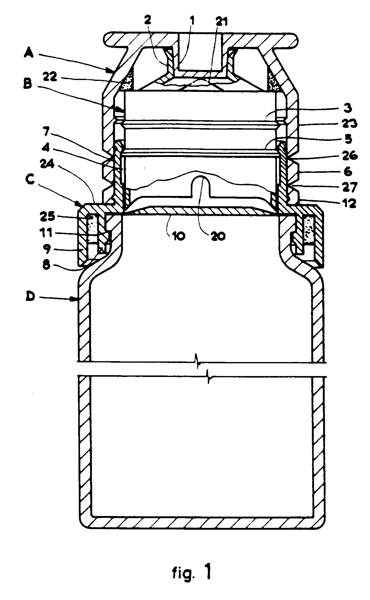
04.03.1998 Bulletin 1998/10 |
| (22) |
Date of filing: 18.11.1993 |
|
| (51) |
International Patent Classification (IPC)6: B65D 51/28 |
|
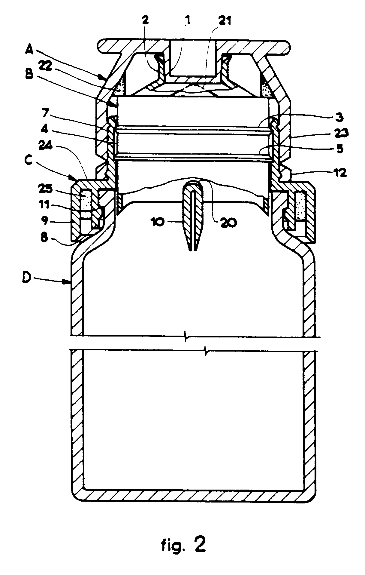
| (54) |
Proportioning device for extemporaneous multidose syrups for pharmaceutical use
Vorrichtung zum Dosieren von pharmazeutischem, mehrfachdosiertem Sirup für die Zubereitung
an Orte und Stelle
Dispositif pour le dosage extemporanée des sirops pharmaceutiques multidose
|
| (84) |
Designated Contracting States: |
|
AT BE CH DE DK ES FR GB GR IE IT LI LU MC NL PT SE |
| (30) |
Priority: |
27.11.1992 IT MI921016 U
|
| (43) |
Date of publication of application: |
|
01.06.1994 Bulletin 1994/22 |
| (73) |
Proprietor: IBSA - INSTITUT BIOCHIMIQUE S.A. |
|
CH-6903 Lugano (CH) |
|
| (72) |
Inventors: |
|
- Mutterle, Antonio
Ch-6932 Breganzona (CH)
- Donati-Pedemonti, Elisabetta
it-22100 Breccia (Province of Como) (IT)
|
| (74) |
Representative: Gervasi, Gemma, Dr. et al |
|
NOTARBARTOLO & GERVASI Srl,
Corso di Porta Vittoria, 9
20122 Milano
20122 Milano (IT) |
| (56) |
References cited: :
EP-A- 0 069 892
EP-A- 0 251 193
CH-A- 505 736
|
EP-A- 0 217 425
EP-A- 0 344 849
FR-A- 2 289 407
|
|
| |
|
|
|
|
| |
|
| Note: Within nine months from the publication of the mention of the grant of the European
patent, any person may give notice to the European Patent Office of opposition to
the European patent
granted. Notice of opposition shall be filed in a written reasoned statement. It shall
not be deemed to
have been filed until the opposition fee has been paid. (Art. 99(1) European Patent
Convention).
|
PRIOR ART
[0001] In the pharmaceutical field there are numerous active principles whose stability
has a short life span once they have been introduced in an aqueous environment. When
however said active principles have to be administered in form of syrup, for instance
to permit the adjustment of the dosage to patient's needs, the pharmaceutical technician
formulates the preparation in form of dry syrup.
[0002] This pharmaceutical form is made up by a bottle containing a granular or powdery
product to which the patient or the chemist adds drinking water up to a preset level,
marked on either the bottle or the label. The addition of water can be made in a preset
quantity by means of a special calibrated proportioning beaker. While the anhydrous
form has a stability which generally lasts for several months, the reconstituted form
remains stable for no more than a few days and often requires to be preserved in a
refrigerator.
[0003] Water addition to dry syrups is a critical point of these pharmaceutical forms, and
in particular:
- the water utilized may not be drinkable, especially in third world countries; besides,
the water utilized, even though it may be bacteriologically pure, may contain mineral
salts that can alterate the drug;
- the total volume may oscillate greatly, as water addition is made difficult by the
label which covers the bottle almost completely. Besides, in adding water, air bubbles
may form within the granular product, which distort the volume of the fluid and which
when the latter is shaken cause the formation of foam layers which hinder a correct
assessment of the level. In this case, the patient stops adding water too soon, which
involves that the drug administered has a concentration higher than the prescribed
posology;
- the same problem occurs with presentations having a separate water proportioner. Introducing
water with the proportioner is no easy operation, and fluid losses often take place
during the pouring, with the already described consequences of an increased drug concentration
or an empirical reintegration of water by the patient, alterating in this way the
final volume.
[0004] These drawbacks, which produce incorrect syrup dosages, may turn out to be particularly
harmful and dangerous in case of antibiotics administration.
[0005] The pharmaceutical market offers several preparations which are presented in monodose
bottles.
[0006] The hydrosensitive active principle in form of powder is contained in the proportioning
plug which is perforated just before the administration, allowing the powder to solubilize
or disperse in the syrup below. The bottle has a drawback in that it can contain,
because of its size, only the volume of one single dose.
[0007] EP-A-344 849 discloses a container cap for powders applicable to a bottle, constituted
by a housing provided with a substantially cylindrical cavity whose lower extremity
is closed by a detachable diaphgram, and by a substantially cylindrical and hollow
piston, which terminates in the shape of a flutemouth while its upper extremity is
closed and from the closed extremity of the piston there extends an annular element
with an inverted L shaped cross- section. When the piston is pushed downwards to make
the powder fall down into the bottle, it causes, thanks to the flouthmouth conformation
of its lower part, the almost total detachment of the diaphgram.
[0008] Figure 2 of EP-A-344 849 shows that after the piston has been pushed downwards, the
partially detached diaphgram remains hanging within the neck of the bottle.
SUMMARY
[0009] We have now found a proportioning device for extemporaneous syrups which permits
to overcome the drawbacks of the prior art advantageously, and which also permits
an easy reconstitution of the syrup.
[0010] Referring to Figure 1, said proportioning device which allows the assembly in one
single structure of all of the constituents of the syrup, comprises a container (D)
for the fluid, a closing plug containing the active principle in subdivided solid
form comprising a tray (C), a removable hood (A) and a perforator (B), coaxial and
internal to said hood (A) and made up by a cylinder-shaped structure having in the
lower part a cutting edge, and a diaphgram (10) separating said closing plug from
said container, which diaphgram is perforated the moment one wishes the active principle
to go down into the active fluid, characterized in that said cutting edge is a dove-tailed
cutting edge interrupted by two windows (20) diametrally opposite to one another,
in correspondance of which the diaphgram (10) is not cut when perforator B goes down
and perforates diaphgram (10), so that said diaphgram is taken up in the windows (20),
folded on itself and blocked in correspondance of its diameter, and said hood is utilizable
as a measure (23).
[0011] Tray (C) is typically divided into two sectors, a lower sector tightly fixed on the
mouth of said container D and an upper sector in which said hood and said perforator
B engage telescopically.
[0012] Preferred and/or typical embodiments of the present invention are illustrated in
the dependent claims.
[0013] The present invention is also directed to the closing plug as defined in claim 1
and in dependent claims, as well as to a process for assembling the proportioning
device according to the present invention, as hereinafter described in the present
application.
[0014] The fact that perforator (B) is characterized by the above illustrated dove-tailed
cutting edge, interrupted by two windows 20 diametrally opposite to one another, in
correspondance of which the diaphgram is not cut during the reconstitution, permits
to fold the diaphgram on itself and to keep it blocked in correspondance of its diameter.
In this way the diaphgram cannot fall into the fluid below, nor it can obstruct the
mouth of the bottle during the pouring.
[0015] Said device permits the administration in subsequent times of several doses, which
are measured utilizing the hood A as a measure, with a great advantage in use, and,
besides, it offers the advantage of an easy fabrication and assembly of the components.
DETAILED DESCRIPTION OF THE INVENTION
[0016] The characteristics and advantages of the proportioning device for extemporaneous
multidose syrups for pharmaceutical use according to this invention will be illustrated
with more details in the following description.
BRIEF DESCRIPTION OF THE DRAWINGS
[0017] The device object of this invention is shown in figures 1 and 2, of which:
figure 1 is a longitudinal section of the device before the use, but ready for use;
figure 2 is the same device once the perforator has been pushed down, perforating
the diaphragm 10 and causing the fall of the active principle into the fluid below.
DESCRIPTION OF THE PREFERRED EMBODIMENT
[0018] The device comprises two elements, namely a container D and a closing plug constituted
by a tray C, a perforator B and a hood A.
[0019] Tray C, which has a bigger diameter lower sector and a smaller diameter upper sector,
united through the horizontal base 24, is applied at the mouth of said container.
The lower sector is fixed to the wall of the mouth of container D by means of a ring-step
11, and ensures the tightness against the base of the mouth thanks to the interposition
of the marginal sector of diaphragm 10. Diaphragm 10 is constituted by a polythene
membrane coupled to an aluminium/polythene film; the latter permit to ensure the tightness
between the fluid contained in the container D and the (hydrosensitive) subdivided
solid contained in the closing plug.
[0020] Diaphragm 10 closes at the bottom perforator B in which the active principle is loaded
in form of powder or granules, and separates it tightly from container D where the
fluid for the solution or the dispersion of the active principle is contained.
[0021] The lower sector of said tray is made up by two cylinder-shaped coaxial elements
8 and 9, stiffened by internal baffles 25 and connected to one another through the
horizontal base 24. A structure forms, suitable for withstanding the pressure exerted
on said base during the assembly, and which has a good aesthetical appearance.
[0022] The upper sector is made up by a cylinder-shaped element 7 equipped, in correspondence
with the upper edge, with a ring-indentation 4, and fit for engaging with perforator
B on the inside, and hood A on the outside.
[0023] Perforator B is made up by a cylinder-shaped structure having in the lower part a
dove-tailed cutting edge, interrupted by two windows 20 diametrally opposite to one
another, in correspondence of which the diaphragm is not cut during the reconstitution.
This permits to fold the diaphragm on itself and to keep it blocked in correspondence
of its diameter. In this way the diaphragm cannot fall into the fluid below, nor can
it obstruct the mouth of the bottle during the pouring. In correspondence of said
cutting edge, diaphragm 10 has a weakening ring to make perforation easier. On the
external surface, the perforator has two ring-steps 3 and 5, which limit the travel
within the upper sector of the tray.
[0024] At the upper end, it has a cylinder-shaped mouth 2 for clutching in indentation 1
of hood A, characterized by a drip-catching flared rim, suitable for pouring the fluid.
[0025] Hood A comprises three sectors: an upper truncated conic cylindrical sector 23 whose
base projects with respect to the truncated conic base; an intermediate sector made
up by a ring-band 6 easily removable in that it adheres to the upper sector and to
the lower sector by means of circumference weakened lines 26 and 27, and equipped
also with a tongue, to make hold and traction easier; a lower ring-sector 12 resting
on the base of the tray.
[0026] The device object of this invention has, among others, the advantage of being assemblable
by means of high-speed automatic machines which provide to dosing and loading the
active principle and the fluid, as well as to the assembly of the various parts.
[0027] In detail, hood A, already assembled with perforator B, is turned upside down, to
contain the necessary quantity of active principle. Tray C is assembled on to the
A/B complex, forming the "container-plug" device which shall be assembled, in its
turn, to container D, previously filled with the constitution fluid.
[0028] To utilize the syrup, ring-band 6 is taken off, causing in this way the overlying
part 23 of hood A to slide downwards. By exerting a pressure on the base of A, the
whole A and B goes down and perforates diaphragm 10 which is taken up in windows 20
and the active principle falls down and solves or disperses in the fluid below. After
the reconstitution phase of the syrup, the perforator, which up to this point had
been an integral part of hood A, becomes integral with tray C and permits to pour
the syrup through its flared cylindrical drip-catching mouth.
[0029] Now, part 23 of hood A is removed which constitutes a proportioning small beaker
or measure, and the first dose of the syrup to be administered is poured in it. Afterwards,
the proportioning beaker is reintroduced as a cover of the device until the second
dose is taken, and so on.
[0030] The removal of element 23 of the hood from mouth 2 of the perforator is made easier
by the presence of pairs of elements 21 and 22, on the external surface of the perforator
and the internal surface of the hood, respectively. Element 21 is tilt-bed shaped
and element 22 is tongue-shaped. The rotation of element 23 causes tongue 22 to slide
along tilt-bed 21 and at the same time said element 23 goes up again. The pairs of
elements 21 and 22 are in number of two or three, arranged along the circumference
at 180° or 120° respectively.
[0031] Container D has a volume that permits to load in it the quantity of fluid necessary
to the reconstitution of the syrup.
[0032] Measure 23 has a volume that permits to load in it the unity dose of syrup, for instance
from 2 ml to 15 ml.
[0033] Hence, the device object of this invention allows the administration of the number
of doses required according to order, during the period of validity of the reconstituted
syrup.
[0034] The following are the construction materials of the various components of the device
object of this invention:
- glass or plastic material for container D;
- polythene or other plastic material for tray C;
- polypropylene or other plastic material for perforator B;
- polythene or other plastic material for hood A;
- polythene-aluminium coupling for diaphragm 10;
All of the materials that constitute the invention can be sterilized
by irradiation or exposure to ethylene oxide, which permits to confect the preparation
in sterile conditions.
[0035] Many variants may be introduced in the device object of this invention, without overstepping
its claim field. In particular, an embodiment may be considered in which the plug
is screw-coupled to the container, always in keeping with the spirit of the invention.
[0036] The fluid loaded in the container D may be constituted by simple purified water or
a simple placebo sucrose-syrup or other acariogenic sugars or a medicated syrup containing
a non-hydrosentitive active principle.
[0037] Preferred placebo syrups have for instance the following composition:
PLACEBO SYRUP 1 : maltitol solution, aromatizers, sweeteners, and/or pH correctors,
purified water;
PLACEBO SYRUP 2: sucrose, aromatizers, sweeteners, and/or pH correctors, purified
water.
[0038] Numerous active principles may be advantageously used for extemporaneous syrups utilizing
the device object of this invention, and in particular, for instance, the following:
Amoxicillin compact;
Amoxicillin powder, disgregants, fluidizers and wetteners; constituents are dry-mixed;
Amoxicillin powder, disgregants, wetteners and diffusers; constituents are wet-granulated;
Amoxicillin powder, disgregants, wetteners and diffusers; constituents are dry-granulated;
Cephalexin compact;
Cephalexin powder mixed with suitable excipients: disgregants, wetteners, diffusers
and fluidizers;
Doxycycline compact;
Doxycycline powder mixed with suitable excipients;
Ampicillin compact;
Ampicillin powder mixed with suitable excipients;
Vitamin complexes;
Naproxen powder;
Naproxen mixed or granulate with suitable excipients;
Mefenamic Acid powder;
Mefenamic Acid mixed or granulate with suitable excipients;
Doxylamine succinate powder or mixture with suitable excipients;
N-acetylcysteine powder.
[0039] The examples hereabove are not to be construed as a limitation and only refer to
some therapeutical classes. The proportioning device, object of this invention, may
actually be used for any active principle which can be administered in form of syrup.
[0040] It ensues from the above description that the use of the device object of this invention
is extremely advantageous. In fact, the mixing of the active principle with the fluid
is carried out in a practical and safe way, without interventions by the chemist or
the patient, and the latter benefits from at least four advantages:
- he performs an objectively easy and safe operation, which is important in particular
with old people;
- he does not run the risk of mistaking the dosage, causing the product to be dangerous;
- he does not risk to pollute the product with unsuitable water;
- he does not expose the product to microbiologic pollution risks.
1. Proportioning device for extemporaneous multidose syrups for pharmaceutical use, which
allows the assembly in one single structure of all of the constituents of the syrup,
comprising a container (D) for the fluid, a closing plug containing the active principle
in subdivided solid form constituted by a tray (C), a removable hood (A) and a perforator
(B), coaxial and internal to said hood (A) and made up by a cylinder-shaped structure
having in the lower part a cutting edge, and a diaphgram (10) separating said closing
plug from said container, which diaphgram is perforated the moment one wishes the
active principle to go down into the active fluid, characterized in that said cutting
edge is a dove-tailed cutting edge interrupted by two windows (20) diametrally opposite
to one another, in correspondance of which the diaphgram (10) is not cut when perforator
B goes down and perforates diaphgram (10), so that said diaphgram is taken up in the
windows (20), folded on itself and blocked in correspondance of its diameter, and
said hood is utilizable as a measure (23).
2. Proportioning device as claimed in claim 1, characterized in that said tray (C) is
distinct in two sectors, a lower sector tightly fixed on the mouth of said container
(D) and an upper sector in which said hood (A) and said perforator (B) engage telescopically.
3. Proportioning device as claimed in claim 2, wherein said upper sector of tray (C)
is made up by a cylinder-shape element (7) equipped in correspondance with the upper
edge with a ring-indentation (4) fit for engaging with perforator (B) on the inside
and hood (A) on the outside, and said perforator (B) has on its external surface two
ring-steps (3) and (5) which limit its travel within said upper sector of tray (C)
so that once perforator (B) has been pushed down and has perforated diaphgram (10),
the perforator (B), which up to this point had been an integral part of hood A, then
becomes integral with tray (C), thus allowing removal of element (23) of hood (A)
which constitutes a small proportioning beaker or measure.
4. Proportioning device according to claim 1, characterized in that said diaphragm (10)
realizes the tightness between said container (D) and said closing plug through the
interposition of its marginal sector.
5. Proportioning device as claimed in claim 1, characterized in that diaphgram (10) closes
at the bottom perforator (B).
6. Proportioning device according to claim 1, characterized in that said lower sector
of tray (C) of the closing plug is constituted by two coaxial cylindric elements (8)
and (9) stiffened by internal sects (25) and connected to one another by means of
a horizontal base (24).
7. Proportioning device according to claim 1, characterized in that the closing plug
is suitable to be screw-coupled to the container.
8. Proportioning device according to anyone of claims from 2 to 7, characterized in that
said lower sector of tray (C) is fixed to the external wall of container (D) in such
a way that no part of tray (C) is internal to container (D).
9. Proportioning device according to claim 2, characterized in that tray (C) has a bigger
diameter lower sector and a smaller diameter upper sector united through the horizontal
base (24), the lower sector is fixed to the wall of the mouth of container (D) by
means of ring-step (11), and the marginal sector of diaphgram (10) is interposed between
ring-step (11) of container (D) and said horizontal base (24).
10. Proportioning device according to claim 1, characterized in that said hood (A) is
constituted by a truncated conic cylindric upper sector (23) whose base projects with
respect to the truncated conic base, an intermediate sector constituted by an easily
removable band (6), and a lower sector (12) which rests on the tray base.
11. Proportioning device according to claim 1, characterized in that pairs of elements
(21) and (22) are present respectively on the external surface of said perforator
and the internal surface of said hood, element (21) being tilt-bed-shaped and element
(22) being tongue-shaped.
12. Proportioning device according to claim 1, characterized in that the perforator (B)
at its upper end has a cylinder-shaped mouth (2) for clutching in indentation (1)
of hood (A).
13. Proportioning device according to claim 12, characterized in that said cylinder-shaped
mouth (2) has a drip-catching flared rim, suitable for pouring the fluid.
14. Proportioning device according to claim 1, constituted by suitable and perfectly sterilizable
plastic materials.
15. Proportioning device according to claim 1, characterized in that said container (D)
is made of glass or plastic material, said tray (C) is made of polythene, said perforator
(B) is made of polypropylene, said hood (A) is made of polythene and said diaphragm
(10) is made of polythene-aluminium coupling.
16. Proportioning device according to claim 1, characterized in that the volume of said
container (D) permits to load in it the quantity of fluid necessary to the reconstitution
of the syrup.
17. Proportioning device according to claim 1, characterized in that the volume of said
measure (23) permits to load in it the unity dose of fluid from 2 to 15 ml.
18. Closing plug suitable for containing an active principle in subdivided solid form
and applicable to a container (D) to form a proportioning device for extemporaneous
multidose syrups for pharmaceutical use, comprising a tray (C), a hood (A) and a perforator
(B), which are as defined in anyone of claims from 1 to 17.
19. Use of a closing plug suitable for containing an active principle in subdivided solid
form, comprising a tray (C), a hood (A) and a perforator (B) which are as defined
in anyone of claims from 1 to 17, in the manufacture of a proportioning device for
extemporaneous multidose syrups.
20. A process for assemblying a proportioning device as claimed in anyone of claims from
1 to 17, which comprises assemblying hood (A) with perforator (B), turning upside
down hood (A) to contain the necessary quantity of active principle, assemblying tray
(C) on to the (A/B) complex, forming the "container-plug" device, assembling such
"container-plug" device to container (D), previously filled with the constitution
fluid.
1. Zuteilvorrichtung für Multidosis-Stegreifsirups zur pharmazeutischen Benutztung, die
das Zusammenfügen aller Bestandteile des Sirups in einer einzigen Struktur ermöglicht,
umfassend einen Behälter (D) für die Flüssigkeit, einen Verschlußstopfen, der den
Hauptwirkstoff in unterteilter Festkörperform enthält und eine Schale (C), eine entfernbare
Kappe (A) und einen zu der Kappe (A) koaxialen und internen Perforierer (B) aufweist
und durch eine zylinderförmige Struktur mit einer Schneidkante in ihrem unteren Teil
und eine Membran (10) gebildet ist, die den Verschlußstopfen von dem Behälter trennt,
wobei die Membran in dem Moment perforiert wird, wo erwünscht wird, daß der Hauptwirkstoff
sich in die aktive Flüssigkeit hinab bewegt,
dadurch gekennzeichnet, daß die Schneidkante eine durch zwei sich diametral einander gegenüberliegende Fenster
(20) unterbrochene schwalbenschwanzförmige Schneidkante ist, wodurch übereinstimmend
die Membran (10) nicht geschnitten wird, wenn sich der Perforierer (B) hinabbewegt
und die Membran (10) perforiert, so daß die Membran in den Fenstern (20) auf sich
selbst gefaltet und in Übereinstimmung mit ihrem Durchmesser blockiert aufgenommen
wird und die Kappe als Meßgefäß (23) verwendbar ist.
2. Zuteilvorrichtung nach Anspruch 1, dadurch gekennzeichnet, daß die Schale (C) in zwei
Abschnitte unterteilt ist, einen dicht auf der Mündung des Behälters (D) befestigten
Unterabschnitt und einen Oberabschnitt, in dem die Kappe (A) und der Perforierer (B)
teleskopartig ineinander eingreifen.
3. Zuteilvorrichtung nach Anspruch 2, dadurch gekennzeichnet, daß der Oberabschnitt der
Schale (C) durch ein zylinderförmiges Element (7) gebildet ist, das in Übereinstimmung
mit der Oberkante mit einer ringförmigen Ausnehmung (4) ausgestattet ist, geeignet
zum Eingreifen in den Perforierer (B) auf der Innenseite und in die Kappe (A) auf
der Außenseite, und der Perforierer (B) auf seiner Außenfläche zwei ringförmige Stufen
(3) und (5) aufweist, die seinen Verfahrweg innerhalb des Oberabschnitts der Schale
(C) derart begrenzen, daß der Perforierer (B), der bislang ein integraler Teil der
Kappe (A) war, einteilig mit der Schale (C) wird, sobald der Perforierer (B) nach
unten gedrückt wurde und die Membran (10) perforiert hat, folglich das Entfernen des
Elements (23) der Kappe (A) ermöglichend, die ein kleines Zuteilbecherglas oder -
meßgefäß bildet.
4. Zuteilvorrichtung nach Anspruch 1, dadurch gekennzeichnet, daß die Membran (10) Dichtheit
zwischen dem Behälter (D) und dem Verschlußstopfen durch die Anordnung ihres Randabschnitts
dazwischen verwirklicht.
5. Zuteilvorrichtung nach Anspruch 1, dadurch gekennzeichnet, daß die Membran (10) den
Perforierer (B) unten verschließt.
6. Zuteilvorrichtung nach Anspruch 1, dadurch gekennzeichnet, daß der Unterabschnitt
der Schale (C) des Verschlußstopfens durch zwei koaxiale Zylinderelemente (8) und
(9) gebildet ist, die durch interne Zwischenwände (25) versteift und miteinander mittels
eines horizontalen Fußes (24) verbunden sind.
7. Zuteilvorrichtung nach Anspruch 1, dadurch gekennzeichnet, daß der Verschlußstopfen
ausgebildet ist, mit dem Behälter schraubgekoppelt zu werden.
8. Zuteilvorrichtung nach mindestens einem der Ansprüche 2 bis 7, dadurch gekennzeichnet,
daß der Unterabschnitt der Schale (C) an der Außenwand des Behälters (D) derart befestigt
ist, daß kein Teil der Schale (C) innerhalb des Behälters (D) ist.
9. Zuteilvorrichtung nach Anspruch 2, dadurch gekennzeichnet, daß die Schale (C) einen
Unterabschnitt mit größerem Durchmesser und einen Oberabschnitt mit kleinerem Durchmesser
aufweist, die durch den horizontalen Fuß (24) vereint sind, wobei der Unterabschnitt
an der Mündungswand des Behälters (D) mittels einer ringförmigen Stufe (11) befestigt
und der Randabschnitt der Membran (10) zwischen der ringförmigen Stufe (11) des Behälters
(D) und dem horizontalen Fuß (24) angeordnet ist.
10. Zuteilvorrichtung nach Anspruch 1, dadurch gekennzeichnet, daß die Kappe (A) durch
einen konischen, zylinderstumpfartigen Oberabschnitt (23), dessen Fuß in bezug auf
den kegelstumpfartigen Fuß vorsteht, einen durch ein leicht entfernbares Band (6)
gebildeten Zwischenabschnitt und einen Unterabschnitt (12) gebildet ist, der auf dem
Schalenfuß ruht.
11. Zuteilvorrichtung nach Anspruch 1, dadurch gekennzeichnet, daß Elementpaare (21) und
(22) jeweils auf der Außenfläche des Perforierers und der Innenfläche der Kappe vorhanden
sind, wobei Element (21) wie ein geneigtes Bett geformt und Element (22) zungenförmig
ist.
12. Zuteilvorrichtung nach Anspruch 1, dadurch gekennzeichnet, daß der Perforierer (B)
an seinem oberen Ende eine zylinderförmige Mündung (2) zum Eingreifen in die Ausnehmung
(1) der Kappe (A) aufweist.
13. Zuteilvorrichtung nach Anspruch 12, dadurch gekennzeichnet, daß die zylinderförmige
Mündung (2) einen Tropfen fangenden aufgeweiteten Rand aufweist, der zum Gießen der
Flüssigkeit ausgebildet ist.
14. Zuteilvorrichtung nach Anspruch 1, dadurch gekennzeichnet, daß sie durch geeignete
und vollkommen sterilisierbare Kunststoffwerkstoffe gebildet ist.
15. Zuteilvorrichtung nach Anspruch 1, dadurch gekennzeichnet, daß der Behälter (D) aus
Glas oder Kunststoffwerkstoff hergestellt ist, die Schale (C) aus Polyethylen hergestellt
ist, der Perforierer (B) aus Polypropylen hergestellt ist, die Kappe (A) aus Polyethylen
hergestellt ist und die Membran (10) aus einem Polyethylen-Aluminiumverbund hergestellt
ist.
16. Zuteilvorrichtung nach Anspruch 1, dadurch gekennzeichnet, daß das Volumen des Behälters
(D) ermöglicht, in ihn die zur Rekonstitution des Sirups notwendige Menge Flüssigkeit
zu füllen.
17. Zuteilvorrichtung nach Anspruch 1, dadurch gekennzeichnet, daß das Volumen des Meßbehälters
(23) ermöglicht, in ihn die Einheitsflüssigkeitsdosis von 2 bis 15 ml zu füllen.
18. Verschlußstopfen, ausgebildet zum Enthalten eines Hauptwirkstoffs in unterteilter
Festkörperform und anwendbar auf einen Behälter (D), um eine Zuteilvorrichtung für
pharmazeutische, Multidosis-Stegreifsirups zu bilden, umfassend eine Schale (C), eine
Kappe (A) und einen Perforierer (B), die wie in mindestens einem der Ansprüche 1 bis
17 definiert sind.
19. Verwendung eines Verschlußstopfens, der zum Enthalten eines Hauptwirkstoffs in unterteilter
Festkörperform ausgebildet ist und eine Schale (C), eine Kappe (A) und einen Perforierer
(B) umfaßt, die wie in mindestens einem der Ansprüche 1 bis 17 definiert sind, zum
Herstellen einer Zuteilvorrichtung für Multidosis-Stegreifsirups.
20. Verfahren zum Zusammensetzen einr Zuteilvorrichtung nach mindestens einem der Ansprüche
1 bis 17, umfassend das Zusammensetzen der Kappe (A) mit dem Perforierer (B), das
Umdrehen der Kappe (A), die die notwendige Menge des Hauptwirkstoffs enthält, das
Anbringen der Schale (C) auf den (A/B) Komplex, das Bilden der

Behälterstopfen"-Vorrichtung, das Zusammensetzen solch einer
Behälterstopfen"-Vorrichtung mit dem Behälter (D), der vorhergehend mit der Konstitutionsflüssigkeit
gefüllt wurde.
1. Dispositif de dosage de sirops multidoses improvisés destiné à une utilisation pharmaceutique,
qui permet l'assemblage en une seule structure de tous les constituants du sirop,
comprenant un récipient (D) pour le fluide, un bouchon de fermeture contenant le principe
actif sous forme solide subdivisée, constitué d'un plateau (C), d'une cloche amovible
(A) et d'un perforateur (B) coaxial et interne à ladite cloche (A) et constitué d'une
structure en forme de cylindre présentant dans la partie inférieure un bord coupant
et un diaphragme (10) séparant ledit bouchon de fermeture dudit récipient, lequel
diaphragme est transpercé au moment où l'on souhaite faire descendre le principe actif
dans le fluide actif, caractérisé en ce que ledit bord coupant est un bord coupant
à queue-d'aronde interrompu par deux fenêtres (20) diamétralement opposées l'une à
l'autre, avec lequel le diaphragme (10) en correspondance n'est pas coupé lorsque
le perforateur (B) descend et transperce le diaphragme (10) de telle sorte que ledit
diaphragme soit soulevé pour pénétrer dans les fenêtres (20), plié sur lui-même et
bloqué de manière correspondante à son diamètre et ladite cloche peut être utilisée
comme mesure (23).
2. Dispositif de dosage selon la revendication 1, caractérisé en ce que ledit plateau
(C) est distinct dans deux secteurs, un secteur inférieur fixé solidement sur l'ouverture
dudit récipient (D) et un secteur supérieur dans lesquels ladite cloche (A) et ledit
perforateur (B) sont mis en prise de manière télescopique.
3. Dispositif de dosage selon la revendication 2, dans lequel ledit secteur supérieur
du plateau (C) est constitué d'un élément en forme de cylindre (7) équipé en correspondance
avec le bord supérieur d'une couronne dentée (4) adaptée pour se mettre en prise avec
le perforateur (B) à l'intérieur et la cloche (A) à l'extérieur, et ledit perforateur
(B) présente sur sa surface externe deux paliers annulaires (3) et (5) qui limitent
son trajet à l'intérieur dudit secteur supérieur du plateau (C) de telle sorte qu'une
fois que le perforateur (B) a été poussé vers le bas et a transpercé le diaphragme
(10), le perforateur (B) qui jusqu'à ce stade constituait une partie intégrale de
la cloche (A), forme ensuite une seule pièce avec le plateau (C), permettant ainsi
le retrait de l'élément (23) de la cloche (A) qui constitue un petit bécher de dosage
ou une mesure.
4. Dispositif de dosage selon la revendication 1, caractérisé en ce que ledit diaphragme
(10) réalise l'étanchéité entre ledit récipient (D) et ledit bouchon de fermeture
par l'interposition de son secteur marginal.
5. Dispositif de dosage selon la revendication 1, caractérisé en ce que le diaphragme
(10) se ferme au niveau du perforateur inférieur (B).
6. Dispositif de dosage selon la revendication 1, caractérisé en ce que ledit secteur
inférieur du plateau (C) du bouchon de fermeture est constitué de deux éléments cylindriques
coaxiaux (8) et (9) rigidifiés par deux sections (25) internes et connectés l'un à
l'autre au moyen d'une base horizontale (24).
7. Dispositif de dosage selon la revendication 1, caractérisé en ce que le bouchon de
fermeture convient pour être couplé par vissage au récipient.
8. Dispositif de dosage selon l'une quelconque des revendications 2 à 7, caractérisé
en ce que ledit secteur inférieur du plateau (C) est fixé sur la paroi interne du
récipient (D) de telle manière qu'aucune partie du plateau (C) ne soit interne au
récipient (D).
9. Dispositif de dosage selon la revendication 2, caractérisé en ce que le plateau (C)
présente un secteur inférieur de diamètre plus grand et un secteur supérieur de diamètre
plus faible reliés par une base horizontale (24), le secteur inférieur est fixé à
la paroi de l'ouverture du récipient au moyen d'un palier annulaire (11) et le secteur
marginal du diaphragme (10) est intercalé entre le palier annulaire (11) du récipient
(D) et ladite base horizontale (24).
10. Dispositif de dosage selon la revendication 1, caractérisé en ce que ladite cloche
(A) est constituée d'un secteur supérieur cylindrique tronconique (23) dont la base
fait saillie par rapport à la base tronconique, d'un secteur intermédiaire constitué
d'une bande pouvant être retirée facilement (6) et d'un secteur inférieur (12) qui
repose sur la base du plateau.
11. Dispositif de dosage selon la revendication 1, caractérisé en ce que des paires d'éléments
(21) et (22) sont présentes respectivement sur la surface externe dudit perforateur
et la surface interne de ladite cloche, l'élément (21) étant en forme de lit incliné
et l'élément (22) ayant la forme d'une languette.
12. Dispositif de dosage selon la revendication 1, caractérisé en ce que le perforateur
(B) au niveau de son extrémité supérieure présente une ouverture en forme de cylindre
(2) pour s'accoupler avec la dentelure (1) de la cloche (A).
13. Dispositif de dosage selon la revendication 12, caractérisé en ce que ladite ouverture
en forme de cylindre (2) présente un bord évasé ramasse-gouttes convenant pour verser
le fluide.
14. Dispositif de dosage selon la revendication 1, constitué de matériaux plastiques adaptés
et pouvant être parfaitement stérilises.
15. Dispositif de dosage selon la revendication 1, caractérisé en ce que ledit récipient
(D) est constitué d'un matériau en verre ou plastique, ledit plateau (C) est constitué
de polythène, ledit perforateur (B) est constitué de polypropylène, ladite cloche
(A) est fabriquée en polythène et ledit diaphragme (10) est constitué d'un couplage
de polythène et d'aluminium.
16. Dispositif selon la revendication 1, caractérisé en ce que le volume dudit récipient
(D) permet de charger à l'intérieur la quantité de fluide nécessaire à la reconstitution
du sirop.
17. Dispositif de dosage selon la revendication 1, caractérisé en ce que le volume de
ladite mesure (23) permet de charger à l'intérieur la dose unitaire de fluide comprise
entre 2 et 15 ml.
18. Bouchon de fermeture adapté pour contenir un principe actif sous forme solide subdivisée
et applicable à un récipient (D) pour former un dispositif de dosage de sirops multidoses
improvisés destiné à une utilisation pharmaceutique, comprenant un plateau (C), une
cloche (A) et un perforateur (B) qui sont tels que définis dans l'une quelconque des
revendications 1 à 17.
19. Utilisation d'un bouchon de fermeture adapté pour contenir un principe actif sous
forme solide subdivisée, comprenant un plateau (C), une cloche (A) et un perforateur
(B) qui sont tels que définis dans l'une quelconque des revendications 1 à 17 dans
la fabrication d'un dispositif de dosage de sirops multidoses improvisés.
20. Procédé d'assemblage d'un dispositif de dosage selon l'une quelconque des revendications
1 à 17, qui comprend les étapes consistant à assembler la cloche (A) avec le perforateur
(B), retourner la cloche (A) pour contenir la quantité nécessaire de principe actif,
assembler le plateau (C) sur le complexe (A/B), former le dispositif "récipient-bouchon",
assembler ce dispositif "récipient-bouchon" sur le récipient (D) rempli au préalable
avec le fluide de constitution.