| (19) |
 |
|
(11) |
EP 0 610 050 B1 |
| (12) |
EUROPEAN PATENT SPECIFICATION |
| (45) |
Mention of the grant of the patent: |
|
30.12.1998 Bulletin 1998/53 |
| (22) |
Date of filing: 31.01.1994 |
|
| (51) |
International Patent Classification (IPC)6: G01F 23/26 |
|
| (54) |
Variable fluid and tilt level sensing probe system
Hessonde für verschiedene Flüssigkeiten und geneigte Flüssigkeitsspiegel
Sonde de mesure pour des liquides divers et pour des miroirs de liquides inclinés
|
| (84) |
Designated Contracting States: |
|
AT DE FR GB IT SE |
| (30) |
Priority: |
01.02.1993 US 11728
|
| (43) |
Date of publication of application: |
|
10.08.1994 Bulletin 1994/32 |
| (73) |
Proprietor: LEE/MAATUK ENGINEERING, INC. |
|
Santa Ana, CA 92705 (US) |
|
| (72) |
Inventor: |
|
- Lee, Calvin s.
Laguna Niguel,
California 92677 (US)
|
| (74) |
Representative: Greenwood, John David et al |
|
Graham Watt & Co.
Riverhead
Sevenoaks
Kent TN13 2BN
Sevenoaks
Kent TN13 2BN (GB) |
| (56) |
References cited: :
EP-A- 0 149 279
US-A- 3 935 739
|
DE-B- 1 250 146
US-A- 5 138 880
|
|
| |
|
|
|
|
| |
|
| Note: Within nine months from the publication of the mention of the grant of the European
patent, any person may give notice to the European Patent Office of opposition to
the European patent
granted. Notice of opposition shall be filed in a written reasoned statement. It shall
not be deemed to
have been filed until the opposition fee has been paid. (Art. 99(1) European Patent
Convention).
|
BACKGROUND OF THE INVENTION
[0001] U.S. Patent 5,138,880 discloses a digital level sensing probe system including digital
probe constructed of two (2) concentric cylinders, forming a set of discrete, cylindrical
capacitors that use the substance whose level is to be measured as a dielectric material.
The set of capacitors is arranged along the axis of measurement where each capacitor
represents a discrete level increment. Each capacitor is assigned a unique time slot
in a switching sequence. The first level capacitor is used as a reference to which
all other capacitors are sequentially compared. In the switching sequence, an AC signal
is applied across each capacitor and compared with the inverted signal which is applied
across the first level capacitor. A logic "1" results when the substance is present
and a logic "0" when the substance is absent. The logic is decoded and converted to
display the appropriate quantity of substance measured.
[0002] The possibility of mounting printed circuit configurations printed in the flat and
mounted in facing relation on flat support elements with appropriate aligned spacing
is mentioned in such Patent.
[0003] The use of individual isolated capacitors arranged along the axis of measurement,
where each capacitor represents a discrete level increment checked sequentially in
a unique time slot switching sequence for presence or absence of fluid, provides marked
advance in accuracy compared to analog probes which depend on variable dielectric
values proportional to wetted level of the probe; also compared to semi-isolated capacitors
employing a common electrode.
BRIEF DESCRIPTION OF THE INVENTION
[0004] For further refinement of accuracy, it has been found desirable to compensate for
tilting of the fluid container when the probe is offset from the geometrical center;
also to accommodate situations where the first fluid level may have a different dielectric
value from the higher level fluid which may impair its qualification as a reference,
as in the case of condensation creating a water level under the principal gasoline,
oil or other fluid to be measured. In order to accommodate the possibility of a different
first level fluid, alternative references are disclosed herein which are not subject
to first fluid level variations.
[0005] By separating discrete level capacitors into plural individual isolated capacitors
in each plane of measurement with the container in normal attitude, the sensing of
differential presence and absence of fluid at the individual capacitors of each level,
may be employed as an indicator of tilting and programmed to compensate for fluid
volume with such tilted attitude.
[0006] In the particular case of a vehicle on a road inclined upwardly or downwardly, a
plurality of capacitors of a discrete level separated in the longitudinal plane of
tilting will suffice for sensing the attitude of container. Such arrangement has been
provided in the present embodiment which integrates the housing, mounting, connector,
capacitive sensors and circuitry into a one-piece body where a custom integrated circuit
may be applied onto the housing to form the entire fluid level sensing system in a
flat configuration.
BRIEF DESCRIPTION OF THE DRAWINGS
[0007]
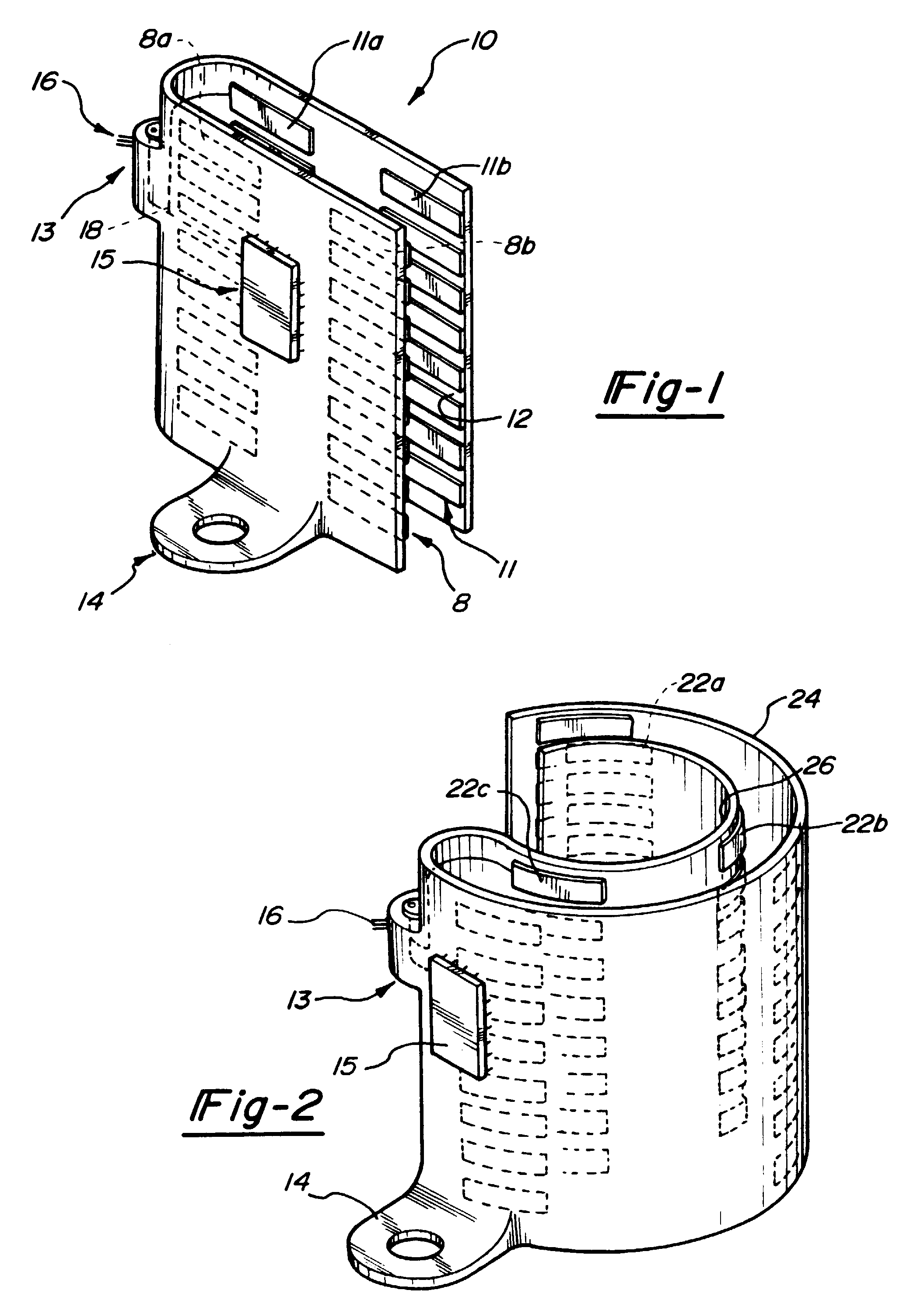
Fig. 1 is a perspective view of a one-piece body incorporating eight dual capacitor
units, mounting pad connector and custom IC pad and circuitry molded into a flat body
for sensing fore and aft tilting;
Fig. 2 is a perspective view of a one-piece body having a three circumferentially
isolated capacitor elements arranged in columns for sensing tilting in any plane;
and
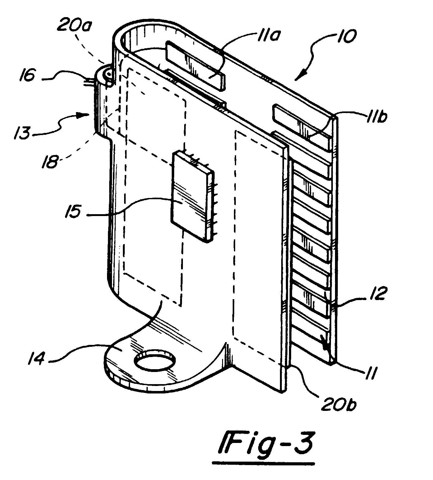
Fig. 3 is a first alternative embodiment of the sensing probe system of Figure 1.
DETAILED DESCRIPTION OF PREFERRED EMBODIMENT
[0008] As shown in Fig. 1 in schematic form, fluid sensor of the present invention comprises
one-piece body 10 having a set of discrete capacitor elements 8, 11 formed as printed
circuits bonded to facing surfaces 12 of body 10 integrally connected by connector
13 with mounting pad 14 and custom IC 15 mounted on exterior surface of body 10 which
may be metalized to provide shielding. Three pins 16 are provided in connector 13
with printed circuit metalization, shown schematically as line 18, brought into the
connector body up to the pin seating.
[0009] While greatest accuracy is obtained by providing completely isolated capacitors,
partial benefits including the economy of a one-piece molded body may be realized
when a common electrodes 20a, 20b, see Fig. 3, provided on one side face individual
discrete capacitor elements at respective levels on the other side.
[0010] In order to detect attitude, the opposed capacitor elements 8, 11 can be separated
into two columns 8a, 11a and 8b, 11b, forward and aft when the fluid sensor is mounted
in the plane of tilting, and the inclination of the fluid calculated from the output
of the opposed capacitor elements 8 and 11.
[0011] As shown in Fig. 2, in order to detect tilting in any plane, three or more circumferentially
isolated capacitors 22a, 22b may be provided at each measurement level in cylindrical
housings 24, 26 such as disclosed in U.S. Patent 5,138,880. By correlating volume
increments of the particular container configuration to be monitored with tilting
at the successive levels and storing the related data in relation to the container
configuration, a more accurate compensated reading may be provided.
[0012] In providing a reference for each discrete capacitor, the first level capacitor may
be employed to which all other capacitors are sequentially compared in a unique time
slot as disclosed in the '880 patent. As mentioned above, in some cases, particularly
when fluid other than the fluid to be measured is at the first level, as where condensed
water settles below oil or gasoline to be measured, it may be better to use a reference
other than the first level capacitor; for example, a fixed reference capacitor, physically
different and not part of the probe body. In such case, the reference capacitor may
be set at a value intermediate the respective capacitance of one of the elemental
capacitors in the probe with or without liquid between its plates.
[0013] Alternatively, a microprocessor may be used to generate all the logic and mutiplexing
functions, in which case, a reference may be stored in the computer's memory which
is proportional to the capacitance of the element. For example, if the element is
in liquid the number might be twenty and when the element is empty, the number might
be seventy. A threshold value of forty-five may be stored in memory and compared with
each elemental number. If greater than forty-five, it is known to be air; if less
than forty-five, liquid is indicated. In actual practice, for example, dielectric
constants may be 1 for air and 2.1 for oil, which are assigned the numerical value
of seventy for air and twenty for oil respectively. Therefore, forty-five gives a
safety margin of plus or minus twenty-five counts between air and oil.
[0014] A fourth referencing method may use each capacitor as a reference for the following
capacitor. Numerical thresholding can again be set at a midpoint.
[0015] With any of the referencing methods, the threshold value is reached when an individual
capacitor is partially covered with the substance to be sensed. The same is true when
the container is at its normal level or tilted to establish differential coverage
of individual capacitors in a multi-capacitor element such as employed at successive
levels to be sensed.
[0016] It will be understood that while two isolated capacitors may be employed to sense
tilting in a single plane, or three 120° capacitors to sense tilting in any plane,
it will be possible to subdivide the plural capacitors for each level into a higher
number of individual isolated capacitors to achieve greater sensitivity in detecting
the tilting angle, which with appropriate stored data related to the configuration
of the container, can provide desired refinement of accuracy in measurement by the
probe.
1. Digital fluid level sensing probe for use in a fluid container comprising a set of
capacitors arranged along an axis of measurement where each capacitor represents a
discrete level increment in a horizontal plane of dielectric fluid to be measured,
each capacitor comprising a pair of individual, electrically, isolated capacitor elements,
each individually subject to dielectric fluid which is present at its level and having
sensible differential capacitance readable relative to a reference having an intermediate
threshold value as to presence or absence of said fluid when addressed in a sequential
individual time slot for each capacitor, plural individual capacitors at each level
being spaced horizontally in columns to sense differentially fluid presence and absence
upon tilting of the container from its normal attitude, the arrangement of said plural
individual capacitors providing means to compensate for volumetric differentials incident
to container tilting for enhanced accuracy of sensing volume indicated by fluid level.
2. Probe of claim 1 wherein said horizontal spacing is in a single plane subject to tilting
differential of fluid presence at the individual capacitors of each level.
3. Probe of claim 2 wherein said probe comprises a one-piece body having two opposed
sides joined by an integral connector, facing surfaces of each side having opposed
adjacent capacitor element spaced to accommodate intermediate dielectric fluid up
to the fluid level in the container.
4. Probe of claim 3 including an integral mounting pad for attachment of said one-piece
body to the bottom surface of said container.
5. Probe of claim 3 wherein an outer surface of said one-piece body is metalized to provide
shielding.
6. A probe as claimed in claim 1 wherein, said probe having a one-piece body with two
opposed sides jointed by an integral connector, facing surfaces of said having said
capacitors secured thereon and spaced to accommodate intermediate dielectric fluid
up to the fluid level in the container, said body having an integral mounting pad.
7. Probe of claim 3 or 6 including a custom integrated circuit pad applied to the outer
surface of one side.
8. Probe of claim 6 wherein a surface of said body is metalized to provide shielding.
9. Probe of claim 6 including terminals provided in said integral connector with circuitry
being brought into said one-piece body up to the terminals in said connector.
10. Digital fluid level sensing probe for use in a fluid container having plural capacitors
each comprising a set of capacitors arranged along an axis of measurement where each
capacitor represents discrete level increment in dielectric fluid to be measured,
and having sensible differential capacitance readable relative to a reference having
an intermediate threshold value as to presence or absence of said fluid when addressed
in sequential individual time slots for each capacitor, said probe having a one-piece
body with two opposed sides joined by an integral connector, facing surfaces of said
sides having said capacitor secured to said facing surfaces and spaced to accommodate
intermediate dielectric fluid up to the fluid level in the container, one side having
discrete isolated capacitors and the other side having a common electrode, said body
having an integral mounting pad, the discrete isolated capacitors of each of the plural
capacitors being spaced horizontally in columns to sense differentially fluid presence
and absence upon tilting of the container from its normal attitude, the arrangement
of said plural individual capacitors providing means to compensate for volumetric
differentials incident to container tilting for enhanced accuracy of sensing volume
indicated by fluid level.
11. Probe of claim 1 or 6 wherein said set of capacitors further includes at least three
of said plural individual capacitors at each level being spaced circumferentially
to sense differentially fluid presence and absence upon tilting of the container in
any direction.
1. Digitale Flüssigkeitsspiegel-Meßsonde zur Verwendung in einem Flüssigkeitsbehälter
mit einem Satz entlang einer Meßachse angeordneten Kondensatoren, von denen jeder
eine diskrete Niveaustufe in einer horizontalen Ebene einer zu messenden dielektrischen
Flüssigkeit definiert und ein Paar von einzelnen, elektrisch isolierten Kondensatorelementen
aufweist, von denen jedes der dielektrischen Flüssigkeit ausgesetzt ist, die sich
auf deren Niveau befindet und eine meßbare Differentialkapazität hat, die bezüglich
einer Referenz mit einem Zwischengrenzwert lesbar ist, der die An- oder Abwesenheit
der Flüssigkeit angibt, wenn dieses in einem einzelnen sequentiellen Zeitfenster für
jeden Kondensator adressiert wird, wobei eine Vielzahl von einzelnen Kondensatoren
in jeder Ebene horizontal im Abstand zueinander in Spalten angeordnet sind, um differential
die An- und Abwesenheit von Flüssigkeit beim Neigen des Behälters aus seiner Normallage
zu messen, wobei die Anordnung der Vielzahl von einzelnen Kondensatoren Mittel zur
Kompensation von sich aus dem Neigen des Behälters ergebenden volumetrischen Differenzen
schafft, um die Genauigkeit des gemessenen Volumens zu verbessern, das durch den Flüssigkeitsspiegel
angegeben wird.
2. Meßsonde nach Anspruch 1, wobei der horizontale Abstand in einer einzelnen Ebene von
dem Neigungsunterschied der an den einzelnen Kondensatoren jedes Niveaus befindlichen
Flüssigkeit abhängig ist.
3. Meßsonde nach Anspruch 2, wobei die Sonde einen einstückigen Körper aufweist, der
zwei gegenüberliegende Seiten hat, die durch einen einstückigen Konnektor miteinander
verbunden sind, wobei die einander zugewandten Oberflächen jeder Seite einander gegenüberliegende
Kondensatorelemente aufweist, die im Abstand zueinander angeordnet sind, um dazwischen
dielektrische Flüssigkeit bis zu dem Flüssigkeitsspiegel in dem Behälter aufzunehmen.
4. Sonde nach Anspruch 3 aufweisend eine integrale Befestigungsunterlage zur Befestigung
des einstückigen Körpers an der Bodenfläche des Behälters.
5. Sonde nach Anspruch 3, wobei eine Außenfläche des einstückigen Körpers zur Schaffung
einer Abschirmung metallisiert ist.
6. Eine Sonde nach Anspruch 1, wobei die Sonde einen einstückigen Körper mit zwei gegenüberliegenden
Seiten hat, die durch einen integralen Konnektor miteinander verbunden sind, wobei
die Kondensatoren an den einander zugewandten Oberflächen derselben befestigt und
im Abstand zueinander angeordnet sind, um dazwischen dielektrische Flüssigkeit bis
zu dem Flüssigkeitsspiegel in dem Behälter aufzunehmen, wobei der Körper eine integrale
Befestigungsunterlage hat.
7. Sonde nach Anspruch 3 oder 6 aufweisend eine kundenspezifisch integrierte Schaltkreisunterlage,
die an die Außenseite einer Seite angebracht ist.
8. Sonde nach Anspruch 6, wobei eine Fläche des Körpers zur Schaffung einer Abschirmung
metallisiert ist.
9. Sonde nach Anspruch 6 aufweisend Anschlüsse, die in dem integralen Konnektor vorgesehen
sind, wobei der Schaltkreis in dem einstückigen Körper bis zu den Konnektoranschlüssen
untergebracht ist.
10. Digitale Flüssigkeitsspiegel-Meβsonde zur Verwendung in einem Flüssigkeitsbehälter
mit einer Vielzahl von Kondensatoren, von denen jeder einen Satz von entlang einer
Meßachse angeordneten Kondensatoren umfaßt, von denen jeder Kondensator eine diskrete
Niveaustufe in einer zu messenden dielektrische Flüssigkeit definiert und eine meßbare
Differentialkapazität hat, die bezüglich einer Referenz mit einem Zwischengrenzwert
lesbar ist, der die An- oder Abwesenheit der Flüssigkeit angibt, wenn dieser in einzelnen
sequentiellen Zeitfenstern für jeden Kondensator adressiert wird, wobei der Sensor
einen einstückigen Körper mit zwei gegenüberliegenden Seiten hat, die durch einen
integralen Konnektor miteinander verbunden sind, wobei die einander zugewandten Flächen
der Seiten den Kondensator an den einander zugewandten Flächen gesichert und im Abstand
zueinander angeordnet haben, um dazwischen dielektrische Flüssigkeit bis zu dem Flüssigkeitsspiegel
in dem Behälter aufzunehmen, wobei eine Seite diskret isolierte Kondensatoren und
die andere Seite eine gemeinsame Elektrode haben, der Körper eine integrale Befestigungsunterlage
hat, die diskret isolierten Kondensatoren von jeder der Vielzahl der Kondensatoren
horizontal im Abstand zueinander in Spalten angeordnet sind, um differentiell die
An- und Abwesenheit von Flüssigkeit beim Neigen des Behälers aus seiner Normallage
zu messen, die Anordnung der Vielzahl von einzelnen Kondensatoren Mittel zur Kompensation
von volumetrischen Unterschieden schafft, die sich aus dem Neigen des Behälters ergeben,
um die Genauigkeit des gemessenen Volumens zu verbessern, das durch den Flüssigkeitsspiegel
angezeigt wird.
11. Sonde nach Anspruch 1 oder 6, wobei der Satz von Kondensatoren ferner wenigstens drei
von der Vielzahl der einzelnen Kondensatoren auf jedem Niveau umfaßt, die umfangsmäßig
verteilt angeordnet sind, um differentiell die An- und Abwesenheit von Flüssigkeit
beim Neigen des Behälters in jede Richtung zu messen.
1. Sonde numérique de détection de niveau de fluide destinée à être utilisée dans un
récipient à fluide comprenant un groupe de condensateurs agencés selon un axe de mesure
dans laquelle chaque condensateur représente un incrément de niveau individuel dans
un plan horizontal de fluide diélectrique à mesurer, chaque condensateur comprenant
deux éléments formant condensateurs individuels isolés électriquement, chacun d'eux
étant soumis individuellement au fluide diélectrique qui est présent à son niveau
et ayant une capacité différentielle sensible lisible par rapport à une référence
ayant une valeur de seuil intermédiaire relative à la présence ou à l'absence dudit
fluide lorsqu'elle est adressée dans une tranche de temps successive individuelle
pour chaque condensateur, plusieurs condensateurs individuels à chaque niveau étant
espacés horizontalement en colonnes pour détecter de manière différentielle la présence
et l'absence de fluide lors d'une inclinaison du récipient par rapport à sa position
normale, la configuration desdits plusieurs condensateurs individuels fournissant
des moyens pour compenser les différences volumétriques dues à l'inclinaison du récipient
pour augmenter la précision de détection du volume indiqué par le niveau de fluide.
2. Sonde selon la revendication 1, dans laquelle ledit espacement horizontal se trouve
dans un plan unique exposé à une différence d'inclinaison relative à la présence du
fluide au niveau des condensateurs individuels de chaque niveau.
3. Sonde selon la revendication 2, dans laquelle ladite sonde comprend un corps en une
pièce comportant deux côtés opposés réunis par un dispositif de raccordement intégré,
les surfaces en vis-à-vis de chaque côté comportant des éléments formant condensateurs
adjacents opposés espacés de façon à adapter le fluide diélectrique intermédiaire
au niveau de fluide dans le récipient.
4. Sonde selon la revendication 3, comprenant une patte de montage intégrée pour fixer
ledit corps en une pièce à la surface de fond dudit récipient.
5. Sonde selon la revendication 3, dans laquelle une surface extérieure dudit corps en
une pièce est métallisée pour founir un blindage.
6. Sonde selon la revendication 1, dans laquelle ladite sonde comporte un corps en une
pièce ayant deux côtés opposés réunis par un dispositif de raccordement intégré, les
surfaces en vis-à-vis de ceux-ci comportant lesdits condensateurs qui y sont assujettis
et étant espacées de façon à adapter le fluide diélectrique intermédiaire au niveau
de fluide dans le récipient, ledit corps comportant une patte de montage intégrée.
7. Sonde selon la revendication 3 ou 6, comprenant un bloc de circuits intégrés de façon
personnalisée appliqué à la surface extérieure d'un côté.
8. Sonde selon la revendication 6, dans laquelle une surface dudit corps est métallisée
pour fournir un blindage.
9. Sonde selon la revendication 6, comprenant des bornes disposées dans ledit dispositif
de raccordement intégré, des circuits étant introduits dans ledit corps en une pièce
jusqu'aux bornes disposées dans ledit dispositif de raccordement.
10. Sonde numérique de détection de niveau de fluide destinée à être utilisée dans un
récipient à fluide comportant plusieurs condensateurs qui comprennent chacun un groupe
de condensateurs agencés selon un axe de mesure, dans laquelle chaque condensateur
représente un incrément de niveau individuel de fluide diélectrique à mesurer, et
ayant une capacité différentielle sensible lisible par rapport à une référence ayant
une valeur de seuil intermédiaire relative à la présence ou à l'absence dudit fluide
lorsqu'elle est adressée par tranches de temps successives individuelles pour chaque
condensateur, ladite sonde comportant un corps en une pièce ayant deux côtés opposés
réunis par un dispositif de raccordement intégré, les surfaces en vis-en-vis desdits
côtés comportant ledit condensateur assujetti aux surfaces en vis-à-vis et étant espacées
de façon à adapter le fluide diélectrique intermédiaire au niveau de fluide dans le
récipient, un côté comportant les condensateurs individuels isolés et l'autre côté
comportant une électrode commune, ledit corps comportant une patte de montage intégrée,
les condensateurs individuels isolés de chacun des plusieurs condensateurs étant espacés
horizontalement en colonnes pour détecter de manière différentielle la présence et
l'absence du fluide lors d'une inclinaison du récipient par rapport à sa position
normale, la configuration desdits plusieurs condensateurs individuels fournissant
des moyens pour compenser les différences volumétriques dues à l'inclinaison du récipient
pour augmenter la précision du volume indiqué par le niveau de fluide.
11. Sonde selon la revendication 1 ou 6, dans laquelle ledit groupe de condensateurs comprend
en outre au moins trois desdits plusieurs condensateurs individuels à chaque niveau
espacés dans le sens de la circonférence pour détecter de manière différentielle la
présence et l'absence du fluide lors d'une inclinaison du récipient dans n'importe
quelle direction.