| (19) |
 |
|
(11) |
EP 0 623 938 B1 |
| (12) |
EUROPEAN PATENT SPECIFICATION |
| (45) |
Mention of the grant of the patent: |
|
08.04.1998 Bulletin 1998/15 |
| (22) |
Date of filing: 25.11.1993 |
|
| (86) |
International application number: |
|
PCT/JP9301/726 |
| (87) |
International publication number: |
|
WO 9412/990 (09.06.1994 Gazette 1994/13) |
|
| (54) |
Ferrite containing magnetic material and method of manufacture of ferrite by sintering
Ferrit enthaltendes magnetisches Material und Herstellung von Ferrit durch Sintern
Matériau comprennant du ferrite et procédé de fabrication de ferrite par frittage
|
| (84) |
Designated Contracting States: |
|
DE FR GB |
| (30) |
Priority: |
25.11.1992 JP 314817/92
16.07.1993 JP 176453/93
19.10.1993 JP 260771/93
|
| (43) |
Date of publication of application: |
|
09.11.1994 Bulletin 1994/45 |
| (73) |
Proprietor: MATSUSHITA ELECTRIC INDUSTRIAL CO., LTD. |
|
Kadoma-shi,
Osaka-fu, 571 (JP) |
|
| (72) |
Inventors: |
|
- INUZUKA, Tsutomu
Kadoma-shi,
Osaka 571 (JP)
- HARADA, Shinji
Kanato-shi,
Osaka 576 (JP)
- FUJI, Hiroshi
Takatsuki-shi,
Osaka 569 (JP)
- OHBA, Michio
Kadoma-shi,
Osaka 571 (JP)
|
| (74) |
Representative: Patentanwälte
Leinweber & Zimmermann |
|
Rosental 7
80331 München
80331 München (DE) |
| (56) |
References cited: :
EP-A- 0 490 245
JP-A- 4 142 003
JP-A-58 135 606
|
JP-A- 3 097 204
JP-A-58 135 177
JP-B-39 020 677
|
|
| |
|
|
- DATABASE WPI Week 9425, Derwent Publications Ltd., London, GB; AN 94-208000 & SU-A-1
809 931 (USSR STRUCTURAL MAKROKINETICS INST.) 15 April 1993
- DATABASE WPI Week 9435, Derwent Publications Ltd., London, GB; AN 94-284689 & SU-C-2
009 561 (USSR STRUCTURAL MAKROKINETICS INST.) 15 March 1994
- DATABASE WPI Week 8031, Derwent Publications Ltd., London, GB; AN 80-54382C & JP-A-55
080 727 (MITSUBISHI)
- DATABASE WPI Week 9206, Derwent Publications Ltd., London, GB; AN 92-046159 & JP-A-3
291 901 (TDK) 24 December 1991
|
|
| |
|
| Note: Within nine months from the publication of the mention of the grant of the European
patent, any person may give notice to the European Patent Office of opposition to
the European patent
granted. Notice of opposition shall be filed in a written reasoned statement. It shall
not be deemed to
have been filed until the opposition fee has been paid. (Art. 99(1) European Patent
Convention).
|
TECHNICAL FIELD
[0001] The present invention relates to a magnetic material used for various kinds of electronic
parts, and a method of manufacturing the same.
BACKGROUND ART
[0002] A conventional magnetic material has been manufactured in the following manner.
[0003] First, ferrite raw powder is previously sintered, thereafter, the sintered mass is
crushed. Particles obtained by the crushing operation are thereafter compressed in
metallic dies. The compact removed from the metallic dies is sintered. Thus, the magnetic
material is obtained. However, it is a well-known fact that the magnetic material
manufactured in the above-described manner inevitably shrinks during the sintering
process, and consequently, the magnetic material is designed considering this shrinkage
so that it will have a slightly larger size than a desired size when it is sintered.
Therefore, after the sintering process, the magnetic material must be cut to have
the desired size and shape. However, since the magnetic material after sintered is
extremely hard, a cutting blade wears considerably, and it must be replaced with a
new one frequently. As a result, the manufacturing cost increase.
[0004] Consequently, there was suggested a magnetic material whose shrinkage during sintering
was substantially prevented so that the above-mentioned cutting operation would not
be required (cf. JP-A-1-264959). This magnetic material is manufactured by mixing
magnetic powder with filling powder which is one kind selected from silicon, titanium
and aluminum, compressing this mixture by metallic dies, and thereafter sintering
the compact, which has been removed from the metallic dies, in an oxygen atmosphere
or in a nitrogen atmosphere. In the case of this conventional magnetic material, oxidization
expansion or nitrogenization expansion of the above-mentioned filling powder can decrease
shrinkage of the magnetic material during sintering to an extremely small degree.
However, silicon, titanium, aluminum or the like which is a non-magnetic material
is mixed in the magnetic powder, and consequently, there arises a problem that the
magnetic property as the magnetic material is deteriorated.
[0005] Thus, an objective of the invention resides in providing a magnetic material whose
dimensional change due to sintering is small and whose magnetic property is not deteriorated.
[0006] In order to achieve the above object, according to the invention, there is provided
a magnetic material as laid down in claim 1 and a manufacturing method as laid down
in claim 16, respectively. Preferred embodiments of the invention are claimed in the
subclaims.
[0007] With the above-described structure, a rate of dimensional change of the magnetic
material due to sintering is low, and deterioration in the magnetic property does
not occur. The reason is that the shrinkage preventing grains are interposed among
the ferrite grains and sintered with the ferrite grains in contact with their outer
peripheries, thereby preventing shrinkage which is caused by ferrite grains approaching
to one another to be bound, as in the case of the conventional magnetic material.
Further, the shrinkage preventing grains are oxidized with oxygen and change into
ferrite when they are sintered with the ferrite grains, so that a non-magnetic material
observed in the conventional magnetic material will not be mixed, and that the magnetic
property will not be deteriorated.
BRIEF DESCRIPTION OF THE DRAWINGS
[0008]
Fig. 1 is an enlarged view showing an internal structure of a magnetic material according
to one embodiment of the present invention;
Fig. 2 is an enlarged view showing one condition of the magnetic material in a manufacturing
process; and
Fig. 3 is a characteristic graph showing a dimensional change rate.
BEST MODE FOR CARRYING OUT THE INVENTION
Example 1:
[0009] A first embodiment of the present invention will be hereinafter described with reference
to the attached drawings. Fig. 1 is an enlarged view showing an internal structure
of a magnetic material in the embodiment of the invention. The magnetic material has
a cylindrical shape or a plate-like shape and comprises a great number of ferrite
grains 1 and contraction preventing grains 2 which are located among the great number
of ferrite grains 1. The ferrite grains 1 are manufactured by mixing and sintering
ferrite raw powder consisting of Fe
2O
3, NiO, ZnO and CuO, these having a mixing mole ratio of 47.2 : 15.5 : 32.1 : 5.2,
crushing the sintered mass, and sintering crushed ferrite particles 1a. Further, the
ferrite grains 1 thus obtained are mixed with metal iron powder 2a having a diameter
of 5 µm or less, as shown in Fig. 2, which amounts to 20 parts by weight of the ferrite
particles 1a, and the mixture is sintered. Thus, the shrinkage preventing grains 2
are formed among the ferrite grains 1, as shown in Fig. 1.
[0010] A manufacturing method of the magnetic material comprises a first step of sintering,
at 1320°C for six hours, ferrite raw powder consisting of Fe
2O
3, NiO, ZnO and CuO which have a mixing mole ratio of 47.2 : 15.5 : 32.1 : 5.2, a second
step of forming ferrite particles 1a by crushing the sintered mass into particles
having a diameter of 40 µm or less, a third step of forming shrinkage preventing grains
2 by mixing metal iron powder 2a having a diameter of 5 µm or less with the ferrite
particles 1a, as shown in Fig. 2, which metal iron powder amounts to 20 pats by weight
of the ferrite particles 1a, a fourth step of forming pellets by adding 7 wt% epoxy
resin to a mixture of the ferrite particles 1a and the metal iron powder 2a, a fifth
step of compressing the formed pellets into an article of a cylindrical shape having
an inner diameter of 7 mm, an outer diameter of 12 mm and a thickness of 3 mm under
a pressure of 3 ton/cm
2, and a sixth step of sintering the compact of the cylinder shape in an electric furnace
at 1200°C.
[0011] In this example, it is a notable characteristic that, as shown in Fig. 2, the metal
iron powder 2a for forming the shrinkage preventing grains 2 is located among the
great number of ferrite grains 1 in the third step, and this mixture is sintered.
[0012] That is to say, by sintering in the sixth step, the metal iron powder 2a thus located
is sintered with the ferrite grains 1 in contact with their outer peripheries, and
also oxidized with oxygen, so that the metal iron powder 2a formed into the shrinkage
preventing grains 2 by sintering will prevent the ferrite grains 1 from approaching
to one another to be sintered, as shown in Fig. 1. As a result, the dimensional change
rate is extremely low.
[0013] In the sixth step, although the ferrite grains 1 are partially sintered with one
another, the metal iron powder 2a is located in large gaps among the ferrite grains
1 without fail, as shown in Fig. 2, so that the ferrite grains 1 will be generally
sintered with the shrinkage preventing grains 2, to thereby prevent shrinkage.
[0014] Moreover, at the time of sintering in the sixth step, the metal iron powder 2a combines
with oxygen in the external atmosphere and is oxidized to increase in diameter. When
the metal iron powder 2a among the ferrite grains 1 is oxidized and expansion, shrinkage
among the ferrite grains 1 is likewise prevented.
[0015] When the metal iron powder 2a is sintered with the ferrite grains 1 on the outer
peripheries thereof, elements are partially diffused and supplied from the ferrite
grains 1, and the above-described oxidization simultaneously takes place, so that
the metal iron powder 2a itself changes into ferrite. By the way, reference numeral
3 in Fig. 1 denotes a gap formed after sintering.
[0016] Fig. 3 illustrates the relationship between a mixing amount of iron metal powder
2a and a dimensional change rate and a mechanical strength of a magnetic material.
As samples, magnetic materials obtained by mixing 0 to 50 parts of metal powder 2a
by weight of ferrite particles 1a of metal iron powder 2a with ferrite particles 1a
are employed. As shown in Fig. 3, when the mixing amount of the metal iron powder
2a is five parts by weight of ferrite particles or less, the mechanical strength is
sufficient, but the effect as the shrinkage preventing grains 2 is so small that the
dimensional change rate during sintering is increased. When the mixing amount of metal
powder is 40 parts by weight of ferrite particles or more, a sufficient mechanical
strength can not be obtained although the dimensional change rate is low. Therefore,
the mixing amount of the metal iron powder 2a should preferably be more than five
parts by weight of ferrite particles and less than 40 parts by weight of ferrite particles.
[0017] Properties of magnetic materials obtained by adding 2 to 30 parts of metals or metallic
compounds other than the metal iron powder 2a by weight of ferrite particles, as the
shrinkage preventing grains 2, and properties of magnetic materials obtained by adding
the metal iron powder 2a are shown in Table 1 for comparison.

[0018] Specimen No. 1 to 16 are the magnetic materials according to this embodiment obtained
by adding various kinds of filling powder (metal iron powder (Fe), metal nickel powder
(Ni), metal zinc powder (Zn), iron oxide powder (FeO)).
[0019] As clearly understood from Table 1, the optimum mixing amounts for decreasing the
dimensional change rates varied in accordance with the kinds of filling powder. However,
as the mixing amount of the filling powder increased, the dimensional change rate
decreased, and magnetic materials which had the same dimensions as the molded articles
could be obtained. Further, in all of specimens No. 1 to 16, sufficient magnetic properties
and mechanical strengths could be obtained.
[0020] Properties of magnetic materials obtained by mixing various kinds of metals at desired
percentages (wt%) as filling powder, and adding 15 to 25 parts of the mixed powder
by weight of ferrite particles to ferrite particles are shown in Table 2 for comparison.

[0021] Specimens No. 17 to 29 are the magnetic materials according to this embodiment obtained
by adding various kinds of filling powder (mixed powder of metal iron powder, metal
nickel powder and metal zinc powder).
[0022] As clearly understood from Table 2, although the filling powder is mixed powder,
magnetic materials whose dimensional change rates are low and which have sufficient
magnetic properties and mechanical strengths could be obtained.
Example 2:
[0023] A second embodiment of the present invention will be now described. Structures of
magnetic materials and their manufacturing methods which are used in Example 2 are
substantially the same as those of Example 1 so that explanations thereof will be
omitted. Properties of the magnetic materials in which filling powder for forming
contraction preventing grains 2 is varied will be described below.
[0024] Properties of magnetic materials obtained by adding 20 to 25 parts of filling powder
by weight of ferrite particles to ferrite particles for forming ferrite grains 1 are
shown in Table 3 for comparison.

[0025] Specimens No. 30 to 35 are the magnetic materials according to this embodiment obtained
by adding various kinds of filling powder (mixed powder of metal iron powder (Fe),
metal nickel powder (Ni) and metal zinc powder (Zn)) at different mixing percentages.
[0026] As clearly understood from Table 3, magnetic materials which had the same dimensions
as the compacts could be obtained, and initial magnetic permeabilities were larger
than those of the specimens of Example 1.
[0027] Properties of magnetic materials obtained by mixing various kinds of metals or various
kinds of metallic oxides as filling powder at percentages substantially equal to the
structural percentage of powder metallic elements which constitute the sample 35,
and adding 25 weight parts of the mixed powder to ferrite particles for forming ferrite
grains 1 are shown in Table 4 for comparison.
TABLE 4
| SPECIMEN NO. |
METAL OR METALLIC OXIDE |
DIMENSIONAL CHANGE RATE (%) |
INITIAL MAGNETIC PERMEABILITY |
MECHANICAL STRENGTH (kgf) |
| 36 |
METAL IRON, |
|
|
|
| NICKEL OXIDE, |
0.0 |
480 |
10.8 |
| ZINC OXIDE |
|
|
|
| 37 |
IRON OXIDE, |
|
|
|
| METAL NICKEL, |
0.0 |
470 |
11.3 |
| ZINC OXIDE |
|
|
|
| 38 |
IRON OXIDE, |
|
|
|
| NICKEL OXIDE, |
0.0 |
470 |
10.4 |
| METAL ZINC |
|
|
|
[0028] Specimens No. 36 to 38 are the magnetic materials according to this embodiment obtained
by adding various kinds of filling powder (mixed powder of metal iron powder (diameter:
5 µm), metal nickel powder (diameter: 3 µm), metal zinc powder (diameter: 7 µm), nickel
oxide powder (diameter: 1 µm), zinc oxide powder (diameter: 1 µm) and iron oxide powder
(diameter: 1 µm)) at different mixing percentages. Among these specimens, the specimen
36 contains metal iron powder, nickel oxide powder and zinc oxide powder at a weight
ratio of 57.6 : 15.0 : 27.4. The specimen 37 contains metal nickel powder, iron oxide
powder and zinc oxide powder at a weight ratio of 9.7 : 67.8 : 22.5. The specimen
38 contains metal zinc powder, nickel oxide powder and iron oxide powder at a weight
ratio of 18.5 : 69.0 : 12.5.
[0029] In the specimens 36 to 38, as clearly understood from Table 4, magnetic materials
which had the same dimensions as the compact could be obtained, and they had sufficient
magnetic properties and mechanical strengths.
[0030] It should be noted that in the specimens 30 to 38, only the X-ray diffraction peaks
which indicated spinel crystal structures were observed, and X-ray diffraction peaks
which indicated crystal structures other than the spinel crystal structures observed
in the samples of Example 1 were not observed.
[0031] This results implies that a sintered product only comprises a ferrite sintered material
having a spinel crystal structure so that a sintered material whose initial magnetic
permeability is more excellent can be obtained.
Example 3:
[0032] A third embodiment of the present invention will be now described. Structures of
a magnetic material and its manufacturing method which are used in Example 3 are substantially
the same as those of Example 1 so that explanations thereof will be omitted. Properties
of the magnetic material in which filling powder is varied will be described below.
[0033] Properties of a magnetic material obtained by mixing metal iron powder (diameter:
5 µm), nickel oxide powder (diameter: 1 µm), zinc oxide powder [diameter: 1 µm) and
copper oxide powder (diameter: 1 µm)) as filling powder at a weight ratio of 55.8
: 12.2 : 27.6 : 4.4 so as to have substantially the same composition as ferrite grains
1, and adding 25 parts of mixed powder by weight of ferrite particles of the mixed
powder to ferrite particles for forming the ferrite grains 1 are shown in Table 5
for comparison.
TABLE 5
| Specimen No. |
DIMENSIONAL CHANGE RATE (%) |
INITIAL MAGNETIC PERMEABILITY |
MECHANICAL STRENGTH (Kgf) |
| 39 |
0.0 |
650 |
12.8 |
[0034] As clearly understood from Table 5, the specimen had a uniform structure, and consequently,
a sintered magnetic material having a larger initial magnetic permeability than that
of Example 2 was obtained. Further, even if the oxides which constitute the above-mentioned
filling powder are metal powder, a similar effect can be obtained.
Example 4:
[0035] A fourth embodiment of the present invention will be now described. Magnetic materials
used in Example 4 are obtained by mixing 50 parts of filling powder containing at
least Zn-system ferrite by weight of ferrite particles with ferrite particles for
forming ferrite grains 1 which are formed of ferrite raw powder having a mixing mole
ratio of 47.8 : 15.2 : 32.0 : 5.0. Structures of the magnetic materials and their
manufacturing methods are substantially the same as those of Example 1 so that explanations
thereof will be omitted. Properties of the magnetic materials will be described below.
[0036] Properties of the magnetic materials according to this embodiment are shown in Table
6 for comparison.
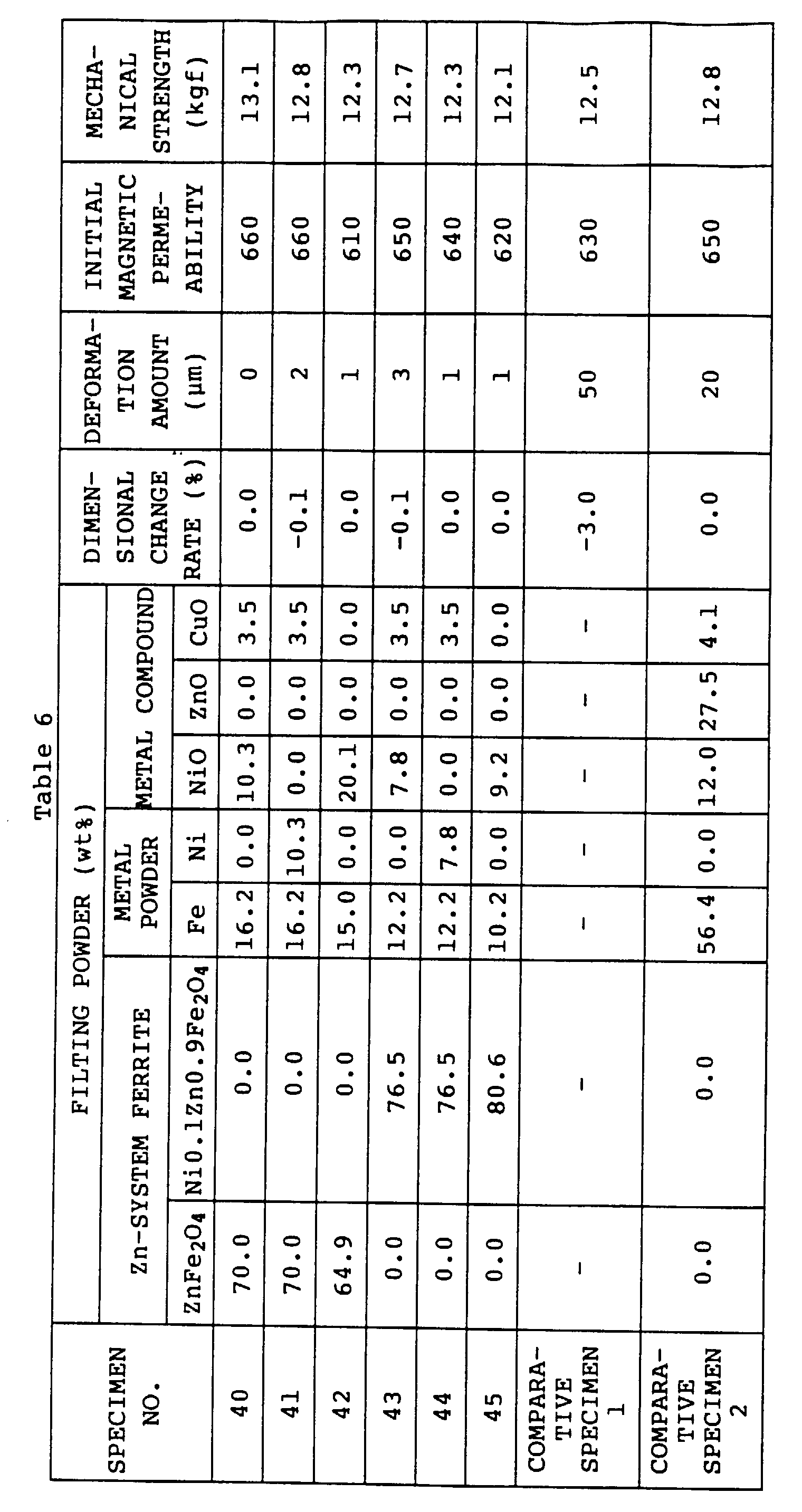
[0037] Specimens No. 40 to 45 are the magnetic materials according to this embodiment, a
comparative specimen 1 is a magnetic material with which filling powder is not mixed
in this embodiment, and a comparative specimen 2 is a magnetic material obtained by
mixing metal iron powder and metal oxides to have substantially the same composition
as ferrite particles without mixing Zn-system ferrite, and mixing 25 weight parts
of this filling powder with the ferrite particles for forming ferrite grains 1 in
this embodiment.
[0038] As clearly understood from Table 6, magnetic properties and mechanical strengths
were substantially the same in the specimens 40 to 45, the comparative specimen 1
and the comparative specimen 2. In the comparative specimen 1 to which filling powder
was not added, dimensional contraction of 3 % occurred during sintering. On the other
hand, the dimensional shrinkage rates could be extremely decreased in the samples
40 to 45 and the comparative specimen 2 to which filling powder was added. Further,
the samples 40 to 45 and the comparative specimen 2 were compared. In the case of
the specimens 40 to 45, because filling powder included Zn-system ferrite, the optimum
mixing amount of the filling powder was increased, but a deformation amount was improved
and lower than that of the comparative specimen 2. It was found that mixing of Zn-system
ferrite powder is effective for manufacturing a magnetic material of a high dimensional
accuracy.
[0039] Initial magnetic permeabilities, dimensional change rates, tensile strengths and
deformation amounts in Example 1, Example 2, Example 3 and Example 4 were calculated
and measured as follows.
[0040] In order to measure the initial magnetic permeability, each sample was prepared by
winding an insulation tape around the above-described annular magnetic material once,
and winding an insulation copper wire having a diameter of 0.26 mm over the entire
circumference of the magnetic material uniformly once. Next, a self-inductance L at
1 MHz was measured by an impedance analyzer when a measuring magnetic field strength
was 0.8 (A/m) or less, and an initial magnetic permeability was calculated.
[0041] The dimensional change rate was obtained by measuring a diameter of the annular molded
article before heat treatment and a diameter of the annular magnetic material after
heat treatment, and calculating a rate of the diameters. A minus denotes contraction.
[0042] In order to measure the tensile strength, two thin wires were inserted in the annular
magnetic material once, and after one of the wires was fixed, the other wire was drawn
in the vertical direction at a speed of 5 mm/min or less. A tensile load at the moment
of breakage of the magnetic material was measured. The deformation amount was obtained
by measuring the maximum value and the minimum value of the diameter of the annular
magnetic material after sintering, and calculating a difference between the values.
INDUSTRIAL APPLICABILITY
[0043] As described heretofore, according to the present invention, the magnetic material
comprises a great number of ferrite grains which are formed by sintering ferrite raw
powder, and shrinkage preventing grains which are interposed among these plural ferrite
grains and which are sintered with the ferrite grains in contact with the outer peripheries
thereof and are also oxidized with oxygen so as to change into ferrite when the grains
are sintered.
[0044] With the above-described structure, there can be provided a magnetic material whose
dimensional change rate due to sintering is low and whose magnetic property is not
deteriorated.
1. A magnetic material, comprising a great number of ferrite grains (1) which are formed
by sintering ferrite raw powder, and shrinkage preventing grains (2) which are interposed
among the plural ferrite grains (1) and which are sintered with said ferrite grains
in contact with the outer peripheries thereof and are also oxidized with oxygen, characterized
in that said shrinking preventing grains (2) change into ferrite when they are sintered.
2. The magnetic material according to claim 1, characterized in that an outer diameter
of the shrinkage preventing grain is smaller than an outer diameter of the ferrite
grain.
3. The magnetic material according to claim 1 or 2, characterized in that the shrinkage
preventing grains are formed of at least one of Fe, FeO, Ni, Zn and Cu which has changed
into ferrite.
4. A magnetic material according to claim 3, characterized in that said shrinkage preventing
grains (2) are formed of Fe and Ni which have changed into ferrite.
5. The magnetic material according to claim 3, characterized in that said shrinkage preventing
grains (2) are formed of Fe and Zn which have changed into ferrite.
6. The magnetic material according to claim 3, characterized in that said shrinkage preventing
grains (2) are formed of Fe, Ni and Zn which have changed into ferrite.
7. The magnetic material according to claim 3, characterized in that said shrinkage preventing
grains (2) are formed of Fe, NiO and ZnO which have changed into ferrite.
8. The magnetic material according to claim 1 or 2, characterized in that said shrinkage
preventing grains (2) are formed of Fe2O3, Ni and ZnO which have changed into ferrite.
9. The magnetic material according to claim 1 or 2, characterized in that said shrinkage
preventing grains (2) are formed of Fe2O3, Nio and Zn which have changed into ferrite.
10. The magnetic material according to claim 1 or 2, characterized in that said shrinkage
preventing grains (2) are formed of compositions having substantially the same elements
as said ferrite grains (1), which elements have changed into ferrite.
11. The magnetic material according to claim 10, characterized in that said ferrite grains
(1) which are formed by sintering ferrite raw powder consist of Fe2O3, Nio, ZnO and CuO, and said shrinkage preventing grains (2) are formed of Fe, NiO,
ZnO and CuO.
12. The magnetic material according to claim 1 or 2, characterized in that said shrinkage
preventing grains (2) are formed of Zn-system ferrite, metal powder and metal oxide
which have changed into ferrite.
13. The magnetic material according to claim 12, characterized in that said metal powder
consists of at least one of Fe and Ni.
14. The magnetic material according to claim 12 or 13, characterized in that said metal
oxide consists of at least one of Nio and CuO.
15. The magnetic material according to any preceding claim, characterized in that the
mixing amount of said shrinkage preventing grains (2) is more than 5 parts and less
than 40 parts by weight of the ferrite grains (1).
16. A manufacturing method of a magnetic material comprising a first step of sintering
ferrite raw powder, a second step of forming ferrite particles (la) by crushing the
sintered mass of said ferrite raw powder obtained in the first step, a third step
of mixing shrinkage preventing filling powder (2a) with said ferrite particles (la)
obtained in the second step, a fourth step of compressing the mixture obtained in
the third step, and a fifth step of sintering the compact obtained in the fourth step
and oxidizing said shrinkage preventing filling powder (2a) used in the third step,
characterized in that in the fifth step said shrinkage preventing filling powder (2a)
is oxidized so as to change into ferrite.
17. The method according to claim 16, characterized in that powder of at least one of
Fe, FeO, Ni, Zn and Cu is used as the filling powder (2a).
18. The method according to claim 17, characterized in that a mixture of Fe powder and
Ni powder is used as the filling powder (2a).
19. The method according to claim 17, characterized in that a mixture of Fe powder and
Zn powder is used as the filling powder (2a).
20. The method according to claim 17, characterized in that a mixture of Fe powder, Ni
powder and Zn powder is used as the filling powder (2a).
21. The method according to claim 17, characterized in that a mixture of Fe powder, Nio
powder and ZnO powder is used as the filling powder (2a).
22. The method according to claim 16, characterized in that a mixture of Fe2O3 powder, Ni powder and ZnO powder is used as the filling powder (2a).
23. The method according to claim 16, characterized in that a mixture of Fe2O3 powder, Nio powder and Zn powder is used as the filling powder (2a).
24. The method according to claim 16, characterized in that a mixture of Fe2O3 powder, Nio powder, ZnO powder and CuO powder is used as the ferrite raw powder (la),
and a mixture of Fe powder, Nio powder, ZnO powder and CuO powder is used as the filling
powder (2a).
25. The method according to claim 16, characterized in that a mixture of Zn-system ferrite
powder, metal powder and metal oxide powder is used as the filling powder (2a).
26. The method according to claim 25, characterized in that powder of at least one of
Fe and Ni is used as said metal powder in the filling powder (2a).
27. The method according to claim 25 or 26, characterized in that at least one of NiO
and CuO is used as said metal oxide powder in the filling powder (2a).
28. The method according to any of claims 16 to 27, characterized in that said sintering
of the compact obtained in the fourth step is performed at a lower temperature than
said sintering in the first step.
29. The method according to any of claims 16 to 28, characterized in that a diameter of
the filling powder is smaller than 10 µm.
1. Magnetmaterial mit einer großen Zahl von Ferritkörnern (1), die hergestellt sind durch
Sintem von Ferritrohpulver, und Schrumpfungsverhinderungskörnern (2), die zwischen
den vielen Ferritkörnern (1) angeordnet und mit den Ferritkörnern in Kontakt mit deren
Außenrand gesintert und ferner mit Sauerstoff oxidiert sind, dadurch gekennzeichnet,
daß sich die Schrumpfungsverhinderungskörner (2) beim Sintern in Ferrit umwandeln.
2. Magnetmaterial nach Anspruch 1, dadurch gekennzeichnet, daß der Außendurchmesser des
Schrumpfungsverhinderungskorns kleiner als der Außendurchmesser des Ferritkoms ist.
3. Magnetmaterial nach Anspruch 1 oder 2, dadurch gekennzeichnet, daß die Schrumpfungsverhinderungskörner
gebildet sind aus zumindest einem aus der Gruppe aus Fe, FeO, Ni, Zn und Cu, das sich
in Ferrit umgewandelt hat.
4. Magnetmaterial nach Anspruch 3, dadurch gekennzeichnet, daß die Schrumpfungsverhinderungskörner
(2) gebildet sind aus Fe und Ni, die sich in Ferrit umgewandelt haben.
5. Magnetmaterial nach Anspruch 3, dadurch gekennzeichnet, daß die Schrumpfungsverhinderungskörner
(2) gebildet sind aus Fe und Zn, die sich in Ferrit umgewandelt haben.
6. Magnetmaterial nach Anspruch 3, dadurch gekennzeichnet, daß die Schrumpfungsverhinderungskörner
(2) gebildet sind aus Fe, Ni und Zn, die sich in Ferrit umgewandelt haben.
7. Magnetmaterial nach Anspruch 3, dadurch gekennzeichnet, daß die Schrumpfungsverhinderungskörner
(2) gebildet sind aus Fe, NiO und ZnO, die sich in Ferrit umgewandelt haben.
8. Magnetmaterial nach Anspruch 1 oder 2, dadurch gekennzeichnet, daß die Schrumpfungsverhinderungskörner
(2) gebildet sind aus Fe2O3, Ni und ZnO, die sich in Ferrit umgewandelt haben.
9. Magnetmaterial nach Anspruch 1 oder 2, dadurch gekennzeichnet, daß die Schrumpfungsverhinderungskörner
(2) gebildet sind aus Fe2O3, NiO und Zn, die sich in Ferrit umgewandelt haben.
10. Magnetmaterial nach Anspruch 1 oder 2, dadurch gekennzeichnet, daß die Schrumpfungsverhinderungskörner
(2) gebildet sind aus Zusammensetzungen mit im wesentlichen den gleichen Elementen
wie die Ferritkörner (1), welche Elemente sich in Ferrite umgewandelt haben.
11. Magnetmaterial nach Anspruch 10, dadurch gekennzeichnet, daß die Ferritkömer (1),
die durch Sintem von Ferritrohpulver gebildet sind, bestehen aus Fe2O3, NiO, ZnO und CuO, und die Schrumpfungsverhinderungskörner (2) gebildet sind aus
Fe, NiO, ZnO und CuO.
12. Magnetmaterial nach Anspruch 1 oder 2, dadurch gekennzeichnet, daß die Schrumpfungsverhinderungskörner
(2) gebildet sind aus Zn-System-Ferrit, Metallpulver und Metalloxyd, die sich in Ferrit
umgewandelt haben.
13. Magnetmaterial nach Anspruch 12, dadurch gekennzeichnet, daß das Metallpulver aus
zumindest Fe oder Ni besteht.
14. Magnetmaterial nach Anspruch 12 oder 13, dadurch gekennzeichnet, daß das Metallpulver
aus zumindest NiO oder CuO besteht.
15. Magnetmaterial nach einem der vorstehenden Ansprüche, dadurch gekennzeichnet, daß
die Mischmenge der Schrumpfungsverhinderungskörner (2) mehr als 5 Teile und weniger
als 40 Teile bezüglich des Gewichts der Ferritkörner (1) ist.
16. Herstellungsverfahren für ein Magnetmaterial mit einem ersten Schritt des Sinterns
von Ferritrohpulver, einem zweiten Schritt der Herstellung von Ferritpartikeln (1a)
durch Zerkleinern der im ersten Schritt erhaltenen Sintermasse des Ferritrohpulvers,
einem dritten Schritt des Mischens von Schrumpfungsverhinderungsfüllpulver (2a) mit
den im zweiten Schritt erhaltenen Ferritpartikeln (1a), einem vierten Schritt der
Kompression der in dem dritten Schritt erhaltenen Mischung, und einem fünften Schritt
des Sinterns des im vierten Schritt erhaltenen Kompaktmaterials und Oxidierens des
in dem dritten Schritt verwendeten Schrumpfungsverhinderungsfüllpulvers (2a), dadurch
gekennzeichnet, daß das Schrumpfungsverhinderungsfüllpulver (2a) im fünften Schritt
oxidiert wird, so daß es sich in Ferrit umwandelt.
17. Verfahren nach Anspruch 16, dadurch gekennzeichnet, daß als das Füllpulver (2a) Pulver
aus zumindest Fe, FeO, Ni, Zn oder Cu verwendet wird.
18. Verfahren nach Anspruch 17, dadurch gekennzeichnet, daß als das Füllpulver (2a) eine
Mischung aus Fe-Pulver und Ni-Pulver verwendet wird.
19. Verfahren nach Anspruch 17, dadurch gekennzeichnet, daß als das Füllpulver (2a) eine
Mischung aus Fe-Pulver und Zn-Pulver verwendet wird.
20. Verfahren nach Anspruch 17, dadurch gekennzeichnet, daß als das Füllpulver (2a) eine
Mischung aus Fe-Pulver, Ni-Pulver und Zn-Pulver verwendet wird.
21. Verfahren nach Anspruch 17, dadurch gekennzeichnet, daß als das Füllpulver (2a) eine
Mischung aus Fe-Pulver, NiO-Pulver und ZnO-Pulver verwendet wird.
22. Verfahren nach Anspruch 16, dadurch gekennzeichnet, daß als das Füllpulver (2a) eine
Mischung aus Fe2O3-Pulver, Ni-Pulver und ZnO-Pulver verwendet wird.
23. Verfahren nach Anspruch 16, dadurch gekennzeichnet, daß als das Füllpulver (2a) eine
Mischung aus Fe2O3-Pulver, NiO-Pulver und Zn-Pulver verwendet wird.
24. Verfahren nach Anspruch 16, dadurch gekennzeichnet, daß als das Ferritrohpulver (1a)
eine Mischung aus Fe2O3-Pulver, NiO-Pulver, ZnO-Pulver und CuO-Pulver verwendet wird und als das Füllpulver
(2a) eine Mischung aus Fe-Pulver, NiO-Pulver, ZnO-Pulver und CuO-Pulver verwendet
wird.
25. Verfahren nach Anspruch 16, dadurch gekennzeichnet, daß als das Füllpulver (2a) eine
Mischung aus Zn-System-Ferrit-Pulver, Metallpulver und Metalloxidpulver verwendet
wird.
26. Verfahren nach Anspruch 25, dadurch gekennzeichnet, daß als das Metallpulver in dem
Füllpulver (2a) Pulver zumindest aus Fe oder Ni verwendet wird.
27. Verfahren nach Anspruch 25 oder 26, dadurch gekennzeichnet, daß als das Metallpulver
in dem Füllpulver (2a) zumindest NiO oder CuO verwendet wird.
28. Verfahren nach einem der Ansprüche 16-27, dadurch gekennzeichnet, daß das Sintern
des im vierten Schritt erhaltenen Kompaktmaterials bei einer niedrigeren Temperatur
als das Sintern im ersten Schritt durchgeführt wird.
29. Verfahren nach einem der Ansprüche 16-28, dadurch gekennzeichnet, daß der Durchmesser
des Füllpulvers kleiner als 10µm ist.
1. Matériau magnétique comprenant un grand nombre de grains de ferrite (1), qui sont
formés par frittage d'une poudre de fer métallique, et des grains empêchant la rétraction
(2) qui sont interposés parmi les grains de ferrite multiples (1) et qui sont frittés
avec lesdits grains de ferrite en contact avec les pourtours externes de ceux-ci et
sont également oxydés par l'oxygène, caractérisés en ce que lesdits grains empêchant
la rétraction (2) se transforment en ferrite lorsqu'ils sont frittés.
2. Matériau magnétique selon la revendication 1, caractérisé en ce qu'un diamètre extérieur
du grain empêchant la rétraction est plus petit qu'un diamètre extérieur du grain
de ferrite.
3. Matériau magnétique selon la revendication 1 ou 2, characterisé en ce que les grains
empêchant la rétraction sont constitués d'au moins l'un de Fe, FeO, Ni, Zn et Cu qui
s'est transformé en ferrite
4. Matériau magnétique selon la revendication 3, caractérisé en ce que lesdits grains
empêchant la rétraction (2) sont formés de Fe et Ni-qui se sont transformés en ferrite.
5. Matériau magnétique selon la revendication 3, caractérisé en ce que lesdits grains
empêchant la rétraction (2) sont constitués de Fe et de Zn qui se sont transformés
en ferrite.
6. Matériau magnétique selon la revendication 3, caractérisé en ce que lesdits grains
empêchant la rétraction (2) sont constitués de Fe, de Ni et de Zn qui se sont transformés
en ferrite.
7. Matériau magnétique selon la revendication 3, caractérisé en ce que lesdits grains
empêchant la rétraction (2) sont constitués de Fe, de NiO et de ZnO qui se sont transformés
en ferrite
8. Matériau magnétique selon la revendication 1 ou 2, caractérisé en ce que les grains
empêchant la rétraction (2) sont constitués de Fe, de Ni et de ZnO qui se sont transformés
en ferrite.
9. Matériau magnétique selon la revendication 1 ou 2, caractérisé en ce que les grains
empêchant la rétraction (2) sont constitués de Fe2O3, de NiO et de Zn qui se sont transformés en ferrite.
10. Matériau magnétique selon la revendication 1 ou 2, caractérisé en ce que les grains
empêchant la rétraction (2) sont constitués de compositions comportant sensiblement
les mêmes éléments que lesdits grains de ferrite (i), lesquels éléments se sont transformés
en ferrite.
11. Matériau magnétique selon la revendication 10, caractérisé en ce que lesdits grains
de ferrite (1) qui sont formés par frittage d'une poudre de fer métallique à l'état
brut se composent de Fe2O3, de NiO, de ZnO et de Cuo et en ce que lesdits grains empêchant la rétraction (2)
sont constitués de Fe, de NiO, de ZnO et de CuO.
12. Matériau magnétique selon la revendication 1 ou 2, caractérisé en ce que lesdits grains
empêchant la rétraction (2) sont constitués de ferrite à Système-Zn, d'une poudre
métallique et d'oxyde métallique qui se sont transformés en ferrite
13. Matériau magnétique selon la revendication 12, caractérisé en ce que ladite poudre
métallique se compose d'au moins l'un de Fe et de Ni.
14. Matériau magnétique selon la revendication 12 ou 13, caractérisé en ce que ledit oxyde
métallique se compose d'au moins l'un de NiO et de CuO.
15. Matériau magnétique selon l'une quelconque des revendications précédentes, caractérisé
en ce que la quantité de mélange desdits grains empêchant la rétraction (2) est supérieure
à 5 parties et inférieure à 40 parties en poids des grains de ferrite (1).
16. Procédé de fabrication d'un matériau magnétique comprenant une première étape consistant
à fritter une poudre de fer métallique à l'état brut, une deuxième étape consistant
à former des particules de ferrite (1a) en broyant la masse frittée de ladite poudre
de fer métallique à l'état brut obtenue dans la première étape, une troisième étape
consistant à mélanger une poudre de remplissage empêchant la rétraction (2a) avec
lesdites particules de ferrite (1a) obtenues dans la deuxième étape, une quatrième
étape consistant à comprimer le mélange obtenu dans la troisième étape et une cinquième
étape consistant à fritter le compact obtenu dans la quatrième étape et à oxyder ladite
poudre de remplissage empêchant la rétraction (2a) utilisée dans la troisième étape,
caractérisé en ce que, dans la cinquième étape, ladite poudre de remplissage empêchant
la rétraction (2a) est oxydée de manière à se transformer en ferrite.
17. Procédé selon la revendication 16, caractérisé en ce qu'une poudre d'au moins l'un
de Fe, de FeO, de Ni, de Zn et de Cu est utilisée comme poudre de remplissage (2a).
18. Procédé selon la revendication 17, caractérisé en ce qu'un mélange de poudre de Fe
et de poudre de Ni est utilisé comme poudre de remplissage (2a).
19. Procédé selon la revendication 17, caractérisé en ce qu'un mélange de poudre de Fe
et de poudre de Zn est utilisé comme poudre de remplissage (2a).
20. Procédé selon la revendication 17, caractérisé en ce qu'un mélange de poudre de Fe,
de poudre de Ni et de poudre de Zn est utilisé comme poudre de remplissage (2a).
21. Procédé selon la revendication 17, caractérisé en ce qu'un mélange de poudre de Fe,
de poudre de NiO et de poudre de ZnO est utilisé comme poudre de remplissage (2a).
22. Procédé selon la revendication 16, caractérisé en ce qu'un mélange de poudre de Fe203,
de poudre de Ni et de poudre de ZnO est utilisé comme poudre de remplissage (2a).
23. Procédé selon la revendication 16, caractérisé en ce qu'un mélange de poudre de Fe2O3, de poudre de NiO et de poudre de Zn est utilisé comme poudre de remplissage (2a).
24. Procédé selon la revendication 16, caractérisé en ce qu'un mélange de poudre de Fe2O3, de poudre de NiO, de poudre de ZnO et de poudre de CuO est utilisé comme poudre
de ferrite à l'état brut (la) et en ce qu'un mélange de poudre de Fe, de poudre de
NiO, de poudre de ZnO et de poudre de CuO est utilisé comme poudre de remplissage
(2a).
25. Procédé selon la revendication 16, caractérisé en ce qu'un mélange de poudre de ferrite
à Système-Zn, de poudre métallique et de poudre d'oxyde métallique est utilisé comme
poudre de remplissage (2a)
26. Procédé selon la revendication 25, caractérisé en ce que une poudre d'au moins l'un
de Fe et de Ni est utilisé comme ladite poudre métallique dans la poudre de remplissage
(2a).
27. Procédé selon la revendication 25 ou 26, caractérisé en ce qu'au moins l'un de NiO
et de CuO est utilisé comme ladite poudre d'oxyde métallique dans la poudre de remplissage
(2a).
28. Procédé selon l'une quelconque des revendications 16 à 27, caractérisé en ce que ledit
frittage du compact obtenu dans la quatrième étape est effectué à une température
inférieure à celle dudit frittage dans la première étape.
29. Procédé selon l'une quelconque des revendications 16 à 28, caractérisé en ce qu'un
diamètre de la poudre de remplissage est plus petit que 10 µm.