| (19) |
 |
|
(11) |
EP 0 679 841 B2 |
| (12) |
NEW EUROPEAN PATENT SPECIFICATION |
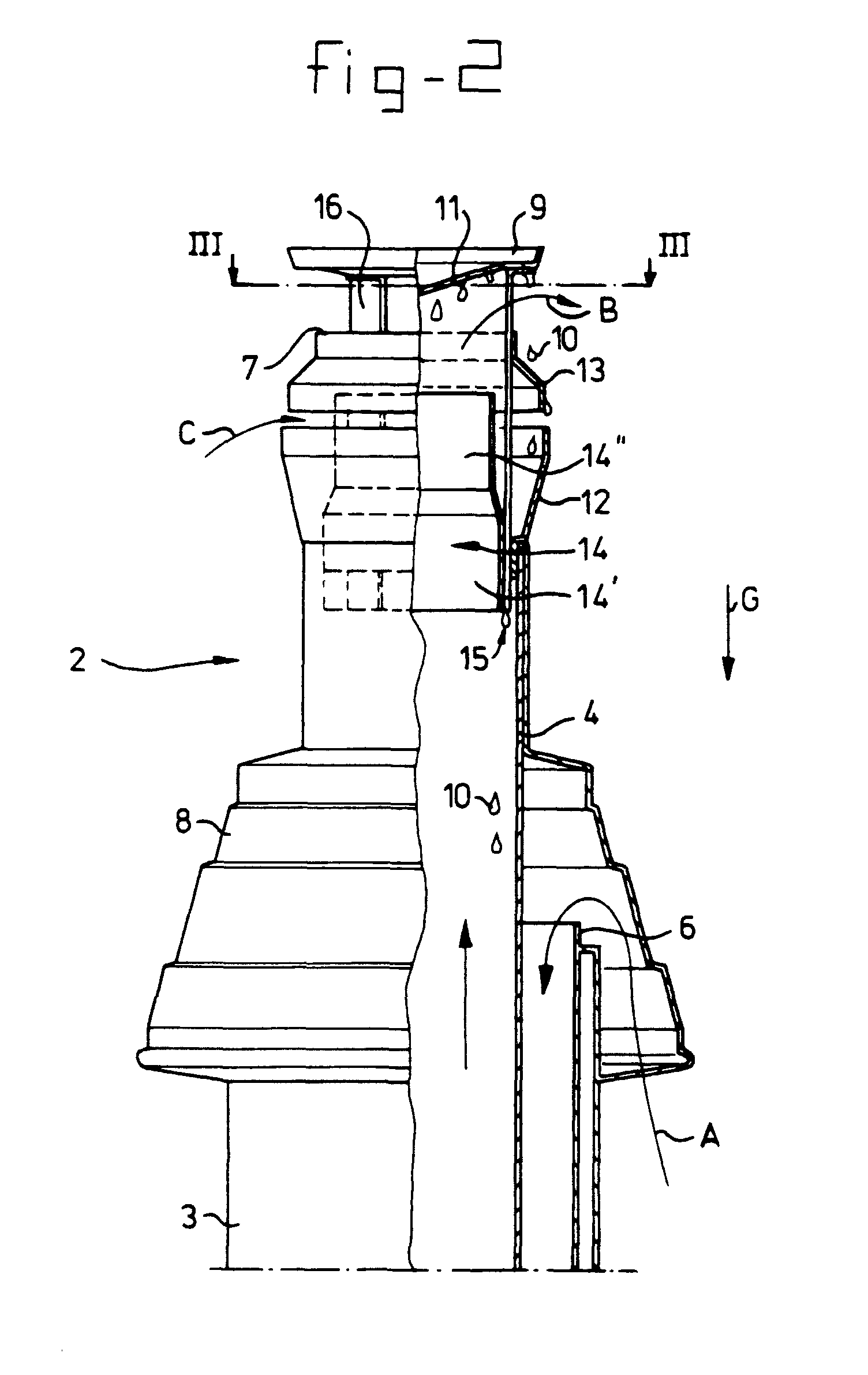
| (45) |
Date of publication and mentionof the opposition decision: |
|
21.05.2003 Bulletin 2003/21 |
| (45) |
Mention of the grant of the patent: |
|
15.10.1997 Bulletin 1997/42 |
| (22) |
Date of filing: 25.04.1995 |
|
|
| (54) |
Assembly of air supply pipe and/or flue gas discharge pipe for connection to a furnace
Anordnung eines Luftzufuhrrohres und/oder eines Rauchgas-Abfuhrrohres für die Verbindung
zu einem Ofen
Ensemble d'un tube d'alimentation en air et/ou d'un tube d'évacuation en gaz de fumée
pour connexion à un four
|
| (84) |
Designated Contracting States: |
|
AT BE CH DE DK FR GB IT LI LU NL |
| (30) |
Priority: |
25.04.1994 NL 9400659
|
| (43) |
Date of publication of application: |
|
02.11.1995 Bulletin 1995/44 |
| (73) |
Proprietor: MUELINK & GROL B.V. |
|
NL-9700 AM Groningen (NL) |
|
| (72) |
Inventors: |
|
- Beekman, Anton
NL-9728 WD Groningen (NL)
- Pestoor, Ietse
NL-9891 AA Ezinge (NL)
- Cantineaux, André
NL-7002 HX Doetinchem (NL)
|
| (74) |
Representative: van Westenbrugge, André et al |
|
Nederlandsch Octrooibureau
P.O. Box 29720
2502 LS The Hague
2502 LS The Hague (NL) |
| (56) |
References cited: :
DE-A- 3 929 578
NL-A- 8 601 344
NL-A- 8 801 181
NL-C- 180 781
|
DE-A- 4 123 614
NL-A- 8 701 809
NL-A- 9 002 786
US-A- 4 280 656
|
|
| |
|
|
|
|
| |
|
[0001] The invention relates to a flue gas discharge assembly according to the preamble
of claim 1, suitable for combustion furnaces, for example for a hot water system or
for a heating system for domestic use. The invention is concerned in particular with
condensation and the problems connected therewith, particularly as the result of ice
formation, for example at low outside temperatures. The invention can be applied both
to individual supply or discharge pipes and to an assembly of supply and discharge
pipe, for example of the type with supply and discharge pipes surrounding each other
concentrically, in an essentially closed furnace, for example of the type described
in EP-A-0,109,620, in particular Fig. 2.
[0002] NL-A-75.096 49 concerns a flue gas discharge of the horizontal type to discharge
flue gases through the wall of a zoom.
[0003] A flue gas discharge assembly according to the preamble of claim 1 is disclosed in
NL-86.01344. This NL-86.01344 reveals a flue gas pipe with collecting means positioned
in the interior of said pipe. These collecting means consist on the one hand of a
plate and on the other hand of an annular gap to which a drain to the outside of the
pipe is connected.
[0004] The object of the invention is providing a flue gas discharge assembly of the vertical
type, which prevents condensation or other liquid from being able to collect in areas
which can become exposed to low temperatures, as a result of which ice can form. For
this purpose, the aim of the invention is to collect condensation and other liquid
in relatively warm areas and to transfer them to other relatively warm areas, where
the chance of ice forming is minimal.
[0005] According to the invention this is achieved by a flue gas discharge assembly according
to claim 1. There is provided a fluid communication in order to ensure that condensation
forming outside the pipes is collected and fed back to the interior of said pipes,
in particular to the interior of the pipe which is being used for discharging the
relatively warm flue gases.
[0006] For returning the condensation and other liquid to the interior of the pipe, it is
advantageous to use a gap whose walls are sufficiently long to prevent air flow inside
said gap from the interior of the pipe to the outside. Condensation and other liquid
is still able to pass through said gap, under the influence of, for example, gravity.
[0007] The invention will become clearer from the description below of a preferred embodiment
of the present invention, with reference to the appended drawings, in which:
Fig. 1 shows diagrammatically a general view of a combustion boiler of the closed
type, provided with an assembly of air supply pipe and/or flue gas discharge pipe
according to the present invention;
Fig. 2 shows a view according to Fig. 1, partially in section, of the top part of
the assembly shown;
Fig. 3 shows a view in section along line III-III in Fig. 2.
[0008] Fig. 1 shows a furnace 1, for example for a water heater (not shown). An assembly
2 is connected to said boiler 1, which assembly has an air supply pipe 3 and a flue
gas discharge pipe 4, running vertically. Along a certain part of the height the air
supply pipe 3 runs in such a way that it surrounds the flue gas discharge pipe 4 concentrically.
In that part of the assembly 2 where the pipes surround each other concentrically,
said assembly projects through the roof 5, so that the two pipes 3, 4 open out into
the atmosphere.
[0009] Figs. 2 and 3 show the opening construction of the pipes 3, 4 in greater detail.
As can be seen from these figures, the opening 6 of the air supply pipe 3 is situated
at a substantial distance below the opening 7 of the flue gas discharge pipe 4. A
cover cap 8 is placed concentrically around the flue gas discharge pipe 4 and, as
shown, covers the opening of the air supply pipe 3. As shown by the arrows A, fresh
air flows through the gap between the cover cap 8 and the air supply pipe 3 into the
opening 6. Said fresh air is drawn in by, for example, a fan (not shown) disposed
in the furnace 1.
[0010] A cover plate 9, which in top view covers the surface of the opening 7 and fits loosely
around it, is provided at an axial distance above the opening 7. Said cover plate
9 prevents, for example, rain entering. Flue gases leave the furnace 1 in the direction
of the arrows B and pass through the gap between the opening 7 and the cover plate
9 into the atmosphere. In this case the relatively warm flue gases meet the relatively
cool cover plate 9. Moisture in the flue gases will consequently condense against
the cover plate 9, which leads to droplets forming. These liquid droplets 10 may possibly
freeze, which can lead to icicles forming. Such ice formation can lead to poorer functioning
of the system, for example through narrowing of the various air gaps. In addition,
a risk from falling ice can occur when the ice is melting. The object of the present
invention is therefore that the condensation forming should be collected at points
where there is least risk of ice forming, or that the condensation should be discharged
into, for example, the sewerage system.
[0011] In the first place, for this purpose the cover plate 9 is constructed in a special
way at the surface facing the opening 7. The cover plate 9 is constructed at that
side with a surface 11 which slopes from the peripheral edge of the cover plate 9
in the direction of the centre thereof towards the opening 7. Under the influence
of gravity (arrow G), liquid droplets 10 forming on said surface 11 will move towards
the centre of the cover plate 9, and will accumulate to form larger liquid droplets
which can be collected in the flue gas discharge pipe 4 situated axially below them.
Inside said flue gas discharge pipe 4 they can be collected, for example, in the bottom
of said pipe 4, and transferred from there to, for example, the sewerage system. For
example, in the case of conventional high-efficiency water heaters for central heating
systems a collecting unit connected to the sewerage system is fitted in the bottom
of the flue gas discharge system, for the purpose of discharging condensation which
forms in the top part of the flue gas discharge pipe, i.e. before the opening 7 is
reached, and precipitates on the inside walls of the flue gas discharge pipe. Such
a known system which is connected to the sewerage system can advantageously be used
in the case of the present invention.
[0012] Secondly, the assembly is also provided with a collecting bowl 12, which is fitted
concentrically around the flue gas pipe 4, with axial space between them, and a ring
13 is fitted, also coaxially with the flue gas discharge pipe 4. The maximum external
diameter of the ring 13 is made smaller in this case than the maximum internal diameter
of the vessel 12. As illustrated, liquid droplets 10 which fall down outside the opening
7 from the cover plate 9 are collected on the ring 13. Flowing along the outside wall
of the ring 13, the liquid droplets 10 ultimately reach the inside of the collecting
bowl 12. If the capacity of the collecting bowl 12 is great enough, the liquid droplets
10 could remain collected therein, and evaporate uniformly, for example in warmer
weather. The volume of the collecting bowl 12 should then be such that the collecting
bowl 12 overflows possibly only in the most extreme circumstances (for example, a
lengthy period of frost).
[0013] However, according to a further aspect of the invention, the interior space of the
collecting bowl 12 is in fluid communication with the flue gas discharge pipe 4. As
shown in Fig. 2, the wall of the collecting bowl 12 forms part of the flue gas discharge
pipe 4. The same applies to the ring 13, the top edge of which defines the opening
7.
[0014] A pipe branch 14 is disposed inside the flue gas discharge pipe 4. Said pipe branch
14 runs from some distance axially below the bottom edge of the bowl 12 past the top
edge of the collecting bowl 12, so that it bridges the axial gap between the collecting
bowl 12 and the ring 13, and projects for some distance into the ring 13. The branch
14 has a relatively broad branch part 14' and a narrower branch part 14', with a conical
transition part between them. The outside wall of the broader branch part 14" defines
a relatively narrow gap with the inside wall of the flue gas discharge pipe 4. Said
gap 15 extends over a considerable distance in the axial direction and is widened
in a stepwise manner in the direction of the furnace 1 (Fig. 1). By way of this gap
15 the annular space bounded between the collecting bowl 12 and the narrower branch
part 14" is in fluid communication with the interior of the flue gas discharge pipe
4 below the branch 14. Droplets 10 can flow through this gap 15 out of the collecting
bowl 12 and further down into the flue gas discharge pipe 4, and are then discharged
to, for example, the sewer, as already explained above. However, the air resistance
in the gap 15 is considerably greater than the air resistance in the branch 14. Combustion
gases will therefore not escape through the gap 15 to the environment. In order to
reinforce this effect, the branch 14 is narrowed above the gap 15, which produces
an acceleration of the flue gases in the area 13. Consequently, it is also ensured
that flue gases escaping through the axial gap between the collecting bowl 12 and
the ring 13 are more likely to follow the route indicated by arrows B. Outside air
is more likely to caused to be drawn in through the axial gap between collecting bowl
12 and the ring 13 in the direction of the arrows (C). The drawing in of said outside
air means that a reliable collection of liquid droplets 10 in the collecting bowl
12 is promoted further, since the liquid droplets 10 undergo a radially inward directed
force as soon as they come away from the ring 13.
[0015] The gap 15 runs all the way around. It is interrupted only at the position of the
supporting strips 16, which run from the bottom side of the collecting bowl 12 to
the cover plate 9. The branch 14 is connected by way of the supporting strips 16 to
the flue gas discharge pipe 4, with a fixing flange of the cap 8 between them. The
ring 13 and the cover plate 9 are also suspended from the supporting strips 16. The
collecting bowl 12 is pushed tightly over the supporting strips 16, and is connected
thereto by friction. Of course, the collecting bowl 12 can also be connected by mechanical
fixing means or by welding to the supporting strips 16 or any other suitable supporting
element, such as the flange of the cap 8 or the flue gas discharge pipe 4.
[0016] It will be clear that variants of embodiments other than those shown here also lie
with the scope of the present invention. For example, the collecting bowl 12 can be
provided in the bottom thereof with an annular pattern of holes, by means of which
the fluid communication with the interior of the flue gas discharge pipe 4 is ensured.
Said pattern of holes can then be arranged in such a way that flue gases do not escape
from the flue gas discharge pipe 4 through said pattern of holes into the environment.
For example, in such a situation the gap 15 can be wider. In that case also, it is
possible, for example, to shorten the distance over which the gap 15 extends, by shortening
the branch 14. The underside of the branch 14 can, for example, be connected directly
to the bottom of the collecting bowl 12, and does not then project further downwards.
In addition, the narrowing in the branch 14 is not absolutely necessary. An acceleration
of the gas flow through the branch 14 could also be achieved in another way. Moreover,
the collecting bowl 12 can also be shaped differently, for example with convex walls
instead of the flat walls shown here. It could also have completely vertical side
walls. The ring 13 may be omitted if desired, or it could be shaped differently if
desired, for example with convex side walls. The inverted funnel shape thereof shown
here is not absolutely essential. The axial gap between the collecting bowl 12 and
the ring 13 may also be omitted, in which case, for example, the ring 13 projects
into the collecting bowl 12. What is important is that the liquid droplets 10 falling
vertically downwards from each surface higher up can be collected in the collecting
bowl 12. It is a further advantage in this case for liquid which has been collected
in the collecting bowl 12 to be fed back into a pipe 3, 4 connected to the furnace
1. A variant which is the reverse of what is shown is also possible, in the case of
which the flue gas discharge pipe 4 is fitted concentrically around the air supply
pipe 3, and the air supply pipe 3 projects past the flue gas discharge pipe 4 and
opens out into the atmosphere.
1. A flue gas discharge assembly (2) suitable for connection to the flue discharge opening
of a combustion furnace of, for example a heating boiler or water heater, the assembly
comprising a flue gas discharge pipe (4, 14) provided with collecting means (12) for
collecting condensation, in which a covering element (9) covering the cross section
of the flue gas pipe (4, 14) is arranged at an axial distance from the opening of
said pipe which faces away from the furnace so that fluid flow between said covering
element (9) and the outlet opening of the discharge pipe is permitted, characterized in that the collecting means comprise a collecting bowl element (12), the periphery of the
bowl being adapted to the covering element (9) and coaxial therewith, in which the
collecting bowl element is arranged outside the flue gas discharge pipe (4, 14) and
connected to said pipe, such that condensation formed outside the discharge assembly
above said bowl (12) is collected in said bowl (12) the collecting means (12) being
in fluid communication with the interior of the flue gas discharge pipe (4) such that
fluid collected in the collecting bowl element (12) can flow into the flue gas discharge
pipe.
2. Flue gas discharge assembly (2) according to claim 1, characterized in that, said collecting bowl element (12) extends around said discharge pipe (4,14) and preferably
is coaxially therewith.
3. Flue gas discharge assembly (2) according to one or more of the preceding claims,
characterized in that, an annular element (13) is disposed above the collecting bowl element (12), which
annular element (13) defines a drip edge which lies inside the upwardly facing edge
of the collecting bowl element (12).
4. Flue gas discharge assembly according to claim 3, characterized in that, the annular element (13) has walls sloping relative to the lengthwise direction
of the flue gas discharge pipe (4,14).
5. Flue gas discharge assembly according to claim 3 or 5, characterized in that, the annular element (13) projects into the collecting bowl element (12).
6. Flue gas discharge assembly according to one or more of the claims 3-4, characterized in that, an axial space is maintained between the collecting bowl element (12) and annular
element (13).
7. Flue gas discharge assembly (2) according to one or more of the claims 3-6, characterized in that, the covering element (9) is arranged above the annular element (13).
8. Flue gas discharge assembly according to one of the preceding claims, characterized in that, the covering element (9) has a wall part (11) which slopes from the periphery towards
the centre line of the pipes (4,13,14) in the direction of the opening of said pipe
(4).
9. Flue gas discharge assembly according to one or more of the preceding claims, characterized in that, the collecting bowl element (12) is in fluid communication with the interior of the
pipe by way of an annular gap, while the walls of said annular gap are designed in
such a way that a considerable air resistance to gas flow through said gap is set
up by comparison with the air resistance inside the pipe (4).
10. Flue gas discharge assembly according to one or more of the preceding claims characterized in that, the collecting bowl element (12) surrounds a pipe branch (14) projecting from said
discharge pipe (4), and that the collecting vessel element (12) defines the continuation
of the opening of said pipe (4).
11. Flue gas discharge assembly according to claim 10 in combination with at least claim
3, characterized in that, said pipe branch (14) opens out inside said annular element (13).
12. Flue gas discharge assembly (2) according to one or more of the preceding claims,
characterized in that, elements are disposed in the area inside the collecting bowl element (12), for causing
an acceleration of the air flow coming from or flowing through the discharge pipe
(4).
13. Flue gas discharge assembly (2) according to one or more of the preceding claims,
characterized in that, the flue gas discharge pipe (4) runs over at least a part of the length thereof inside
an air supply pipe (6) or that an air supply pipe runs over at least a part of the
length thereof inside the flue gas discharge pipe, and in which at the side facing
away from the furnace said pipes (4,6) end at a distance from each other, related
to the lengthwise direction of the pipes.
1. Rauchgasabfuhranordnung (2), die zur Verbindung mit der Rauchgasabfuhröffnung eines
Verbrennungsofens, beispielsweise eines Heizkessels oder Warmwasserbereiters, geeignet
ist und folgendes umfaßt: ein Rauchgasabfuhrrohr (4 14), das mit Auffangmitteln (12)
zum Auffangen von Kondensation versehen ist, wobei ein den Querschnitt des Rauchgasrohrs
(4, 14) bedeckendes Abdeckelement (9) in einem axialen Abstand von der von dem Ofen
weg weisenden Öffnung des Rohrs angeordnet ist, so daß Fluidströmung zwischen dem
Abdeckelement (9) und der Auslaßöffnung des Abfuhrrohrs gestattet wird, dadurch gekennzeichnet, daß die Auffangmittel ein Auffangschalenelement (12) umfassen, wobei der Umfang der Schale
an das Abdeckelement (9) angepaßt und koaxial damit ist, wobei das Auffangschalenelement
außerhalb des Rauchgasabfuhrrohrs (4, 14) angeordnet und mit dem Rohr verbunden ist,
so daß außerhalb der Abfuhranordnung über der Schale (12) gebildete Kondensation in
der Schale (12) aufgefangen wird, daß die Auffangmittel (12) in Strömungsverbindung
mit dem Inneren des Rauchgasabfuhrrohrs (4) stehen, so daß in dem Auffangschalenelement
(12) aufgefangene Flüssigkeit in das Rauchgasabfuhrrohr fließen kann.
2. Rauchgasabfuhranordnung (2) nach Anspruch 1, dadurch gekennzeichnet, daß sich das Auffangschalenelement (12) um das Abfuhrrohr (4, 14) herum erstreckt und
vorzugsweise damit koaxial ist.
3. Rauchgasabfuhranordnung (2) nach einem oder mehreren der vorhergehenden Ansprüche,
dadurch gekennzeichnet, daß über dem Auffangschalenelement (12) ein ringförmiges Element (13) angeordnet ist,
das einen Tropfrand definiert, der innerhalb des nach oben weisenden Rands des Auffangschalenelements
(12) liegt.
4. Rauchgasabfuhranordnung nach Anspruch 3, dadurch gekennzeichnet, daß das ringförmige Element (13) Wände aufweist, die bezüglich der Längsrichtung des
Rauchgasabfuhrrohrs (4, 14) geneigt sind.
5. Rauchgasabfuhranordnung nach Anspruch 3 oder 4, dadurch gekennzeichnet, daß das ringförmige Element (13) in das Auffangschalenelement (12) hineinragt.
6. Rauchgasabfuhranordnung nach Anspruch 3 und/oder 4, dadurch gekennzeichnet, daß zwischen dem Auffangschalenelement (12) und dem ringförmigen Element (13) ein axialer
Abstand aufrechterhalten ist.
7. Rauchgasabfuhranordnung (2) nach einem oder mehreren der Ansprüche 3 bis 6, dadurch gekennzeichnet, daß das Abdeckelement (9) über dem ringförmigen Element (13) angeordnet ist.
8. Rauchgasabfuhranordnung nach einem der vorhergehenden Ansprüche, dadurch gekennzeichnet, daß das Abdeckelement (9) einen Wandteil (11) aufweist, der sich in Richtung der Öffnung
des Rohrs (4) vom Umfang zur Mittellinie der Rohre (4, 13, 14) neigt.
9. Rauchgasabfuhranordnung nach einem oder mehreren der vorhergehenden Ansprüche, dadurch gekennzeichnet, daß das Auffangschalenelement (12) über einen ringförmigen Spalt mit dem Inneren des
Rohrs in Strömungsverbindung steht, während die Wände des ringförmigen Spalts so ausgeführt
sind, daß im Vergleich zu dem Luftwiderstand im Rohr (4) ein beträchtlicher Luftwiderstand
gegen die Gasströmung durch den Spalt hervorgerufen wird.
10. Rauchgasabfuhranordnung nach einem oder mehreren der vorhergehenden Ansprüche, dadurch gekennzeichnet, daß das Auffangschalenelement (12) einen aus dem Abfuhrrohr (4) ragenden Rohrstutzen
(14) umgibt und daß das Auffangbehälterelement (12) die Fortführung der Öffnung des
Rohrs (4) definiert.
11. Rauchgasabfuhranordnung nach Anspruch 11 in Kombination mit mindestens Anspruch 4,
dadurch gekennzeichnet, daß der Rohrstutzen (14) in das ringförmige Element (13) mündet.
12. Rauchgasabfuhranordnung (2) nach einem oder mehreren der vorhergehenden Ansprüche,
dadurch gekennzeichnet, daß in dem Bereich innerhalb des Auffangschalenelements (12) Elemente zum Bewirken einer
Beschleunigung des von dem Abfuhrrohr (4) kommenden oder dadurch strömenden Luftstroms
angeordnet sind.
13. Rauchgasabfuhranordnung (2) nach einem oder mehreren der vorhergehenden Ansprüche,
dadurch gekennzeichnet, daß das Rauchgasabfuhrrohr (4) über mindestens einen Teil seiner Länge innerhalb eines
Luftzufuhrrohrs (6) verläuft oder daß ein Luftzufuhrrohr über mindestens einen Teil
seiner Länge innerhalb des Rauchgasabfuhrrohrs verläuft, und wobei die Rohre (4, 6)
auf der von dem Ofen weg weisenden Seite bezüglich der Längsrichtung der Rohre in
einem Abstand voneinander enden.
1. Assemblage de décharge de gaz de fumée (2) approprié pour être relié à l'ouverture
de décharge du tube-foyer d'un four à combustion, par exemple d'une chaudière de chauffage
ou d'un chauffe-eau, l'assemblage comprenant un tuyau de décharge des gaz de fumée
(4, 14) muni de collecteurs (12) pour collecter la condensation, dans lequel un élément
de recouvrement (9) recouvrant la section transversale du tuyau des gaz de fumée (4,
14) est arrangé à une certaine distance axiale de l'ouverture dudit tuyau opposée
au four de telle sorte que l'écoulement de fluide entre ledit élément de recouvrement
(9) et l'ouverture de sortie du tuyau de décharge est permis, caractérisé en ce que les collecteurs comprennent un bol collecteur (12), la périphérie du bol étant adaptée
à l'élément de recouvrement (9) et coaxiale à ce dernier, dans lequel le bol collecteur
est arrangé à l'extérieur du tuyau de décharge des gaz de fumée (4, 14) et relié audit
tuyau, de telle sorte que la condensation qui se forme à l'extérieur de l'assemblage
de décharge au-dessus dudit bol (12) est récoltée dans ledit bol (12), les collecteurs
(12) se trouvant en communication de fluide avec l'intérieur du tuyau de décharge
(4) de telles sorte que le fluide récolté dans le bol collecteur (12) peut s'écouler
dans le tuyau de décharge des gaz de fumée.
2. Assemblage de décharge de gaz de fumée (2) selon la revendication 1, caractérisé en ce que ledit bol collecteur (12) s'étend autour dudit tuyau de décharge (4, 14) et est de
préférence coaxial avec ce dernier.
3. Assemblage de décharge de gaz de fumée (2) selon une ou plusieurs des revendications
précédentes, caractérisé en ce qu'un élément annulaire (13) est disposé au-dessus du bol collecteur (12), ledit élément
annulaire (13) définissant un bord d'égouttage qui est disposé à l'intérieur du bord
du bol collecteur (12) orienté vers le haut.
4. Assemblage de décharge de gaz de fumée selon la revendication 3, caractérisé en ce que l'élément annulaire (13) possède des parois inclinées par rapport à la direction
longitudinale du tuyau de décharge des gaz de fumée (4, 14).
5. Assemblage de décharge de gaz de fumée selon la revendication 3 ou 4, caractérisé en ce que l'élément annulaire (13) fait saillie dans le bol collecteur (12).
6. Assemblage de décharge de gaz de fumée selon l'une ou plusieurs des revendication
3-4, caractérisé en ce qu'on maintient un espace axial entre le bol collecteur (12) et l'élément annulaire (13).
7. Assemblage de décharge de gaz de fumée (2) selon l'une ou plusieurs des revendications
3-6, caractérisé en ce que l'élément de recouvrement (9) est arrangé au-dessus de l'élément annulaire (13).
8. Assemblage de décharge de gaz de fumée selon l'une quelconque des revendications précédentes,
caractérisé en ce que l'élément de recouvrement (9) possède une partie de paroi (11) dont la pente s'étend
depuis la périphérie en direction de la médiane des tuyaux (4, 13, 14) dans la direction
d'ouverture dudit tuyau (4).
9. Assemblage de décharge de gaz de fumée selon l'une ou plusieurs des revendications
précédentes, caractérisé en ce que le bol collecteur (12) se trouve en communication de fluide avec l'intérieur du tuyau
au moyen d'un espace libre annulaire, tandis que les parois dudit espace libre annulaire
sont conçues de telle sorte qu'une résistance considérable de l'air à l'écoulement
de gaz s'établit à travers ledit espace libre par comparaison à la résistance de l'air
régnant à l'intérieur du tuyau (4).
10. Assemblage de décharge de gaz de fumée selon une ou plusieurs des revendications précédentes,
caractérisé en ce que le bol collecteur (12) entoure une tubulure (14) faisant saillie par rapport audit
tuyau de décharge (4) et en ce que le récipient collecteur (12) définit le prolongement de l'ouverture dudit tuyau (4).
11. Assemblage de décharge de gaz de fumée selon la revendication 10 en combinaison avec
au moins la revendication 3, caractérisé en ce que ladite tubulure de tuyau (14) s'ouvre à l'intérieur dudit élément annulaire (13).
12. Assemblage de décharge de gaz de fumée (2) selon une ou plusieurs des revendications
précédentes, caractérisé en ce que des éléments sont disposés dans la zone à l'intérieur du bol collecteur (12) pour
provoquer une accélération du courant d'air provenant du tuyau de décharge (4) ou
s'écoulant à travers ce dernier.
13. Assemblage de décharge de gaz de fumée (2) selon une ou plusieurs des revendications
précédentes, caractérisé en ce que le tuyau de décharge des gaz de fumée (4) s'étend, sur au moins une partie de sa
longueur, à l'intérieur du tuyau de décharge des gaz de fumée, et dans lequel, du
côté se détournant du four, lesdits tuyaux (4,6) se terminent à distance l'un de l'autre
par rapport à la direction longitudinale des tuyaux.