| (19) |
 |
|
(11) |
EP 0 692 201 B1 |
| (12) |
EUROPEAN PATENT SPECIFICATION |
| (45) |
Mention of the grant of the patent: |
|
08.09.1999 Bulletin 1999/36 |
| (22) |
Date of filing: 12.06.1995 |
|
| (51) |
International Patent Classification (IPC)6: A24C 5/35 |
|
| (54) |
Method of and apparatus for converting a single layer of rod-shaped articles into
a mass flow
Verfahren und Einrichtung zur Umsetzung einer Schicht von stabförmigen Gegenständen
in einen Massenstrom
Procédé et appareil pour convertir une seule couche d'articles en forme de tige en
un courant de plusieurs couches
|
| (84) |
Designated Contracting States: |
|
AT BE CH DE ES FR GB IT LI NL SE |
| (30) |
Priority: |
14.07.1994 US 274968
|
| (43) |
Date of publication of application: |
|
17.01.1996 Bulletin 1996/03 |
| (73) |
Proprietor: Hauni Maschinenbau Aktiengesellschaft |
|
21033 Hamburg (DE) |
|
| (72) |
Inventors: |
|
- Hoffmann, Wilfried
Richmond,
Virginia 23236 (US)
- Sanmann, Gerd
Sandston,
Virginia 23150 (US)
- Foerster, Joerg
Richmond,
Virginia 23231 (US)
- Trenkner, Peter
Richmond,
Virginia 23231 (US)
|
| (56) |
References cited: :
FR-A- 2 318 787
US-A- 4 938 340
|
GB-A- 2 051 552
|
|
| |
|
|
|
|
| |
|
| Note: Within nine months from the publication of the mention of the grant of the European
patent, any person may give notice to the European Patent Office of opposition to
the European patent
granted. Notice of opposition shall be filed in a written reasoned statement. It shall
not be deemed to
have been filed until the opposition fee has been paid. (Art. 99(1) European Patent
Convention).
|
[0001] The invention relates to improvements in methods of and in apparatus for manipulating
rod-shaped articles, such as plain or filter cigarettes, cigars or cigarillos, filter
rod sections and/or other rod-shaped articles of the tobacco processing industry.
More particularly, the invention relates to improvements in methods of and in apparatus
for converting a single layer of spaced-apart parallel elongated rod-shaped articles
which are advanced sideways (transversely of their length) into a mass flow containing
two or more superimposed layers of parallel articles. The articles of the mass flow
can be arrayed in a so-called quincuncial formation.
[0002] U.S. Pat. No. 4,938,340 granted July 3, 1990 to Horsley et al. for "Conveying rod-like
articles" discloses an apparatus wherein a rotary conveyor delivers a series of successive
rod-shaped articles sideways into the relatively narrow inlet of a channel defined
by one or more upper endless belt conveyors and one or more lower endless belt conveyors.
The width of the channel increases in a direction away from the rotary conveyor so
that the articles in the channel can start the formation of a flow wherein some of
the articles are contacted by the upper conveyor(s) and the remaining articles are
contacted by the lower conveyor(s). The belt conveyors are driven at a speed such
that the width of the spaces between successive articles of the single layer is reduced
to zero not later than at the discharge end of the aforementioned channel. The latter
discharges two superimposed layers of articles into the upper end of a divergent chute
which slopes downwardly toward the receiving end of the upper reach of an endless
belt conveyor serving to advance a multi-layer mass flow of articles to a filter assembling
machine. The chute includes walls which contact the articles of the top layer as well
as the articles of the bottom layer.
[0003] The patentees propose to accelerate successive articles which leave the rotary conveyor
in order to avoid damage from following articles.
[0004] Acceleration of articles above the speed which is imparted thereto by the rotary
conveyor is likely to result in damage to the articles. Furthermore, each and every
article in the aforementioned channel is contacted by at least one belt, and the outer
layers of articles in the divergent chute are contacted by fixed parts including a
strip of semiflexible material and a so-called deadplate. All this is likely to affect
the appearance and/or other desirable characteristics of the conveyed articles.
OBJECTS OF THE INVENTION
[0005] An object of the invention is to provide a novel and improved method of converting
a single layer of rod-shaped articles into a mass flow of two or more superimposed
layers of articles.
[0006] Another object of the invention is to provide a method which ensures the formation
of a homogeneous mass flow of rod-shaped articles.
[0007] A further object of the invention is to provide a method which ensures gentle treatment
of rod-shaped articles which form the single layer and which form the mass flow as
well of articles which advance from the path for the single layer toward the path
for the mass flow.
[0008] An additional object of the invention is to provide a novel and improved method of
converting a single layer of spaced apart rod-shaped articles of the tobacco processing
industry into a mass flow of two or more superimposed layers.
[0009] Still another object of the invention is to provide a novel and improved apparatus
for the practice of the above outlined method.
[0010] A further object of the invention is to provide the apparatus with novel and improved
means for converting a single layer of spaced apart rod-shaped articles into a mass
flow.
[0011] Another object of the invention is to provide the above outlined apparatus with novel
and improved means for reducing the kinetic energy of rod-shaped articles between
the path for the single layer and the path for the mass flow.
[0012] An additional object of the invention is to provide the above outlined apparatus
with novel and improved means for defining or establishing paths for advancement of
rod-shaped articles away from the path for a single layer of articles.
[0013] Still another object of the invention is to provide a machine which embodies or which
cooperates with the above outlined apparatus.
SUMMARY OF THE INVENTION
[0014] One feature of the present invention resides in the provision of an apparatus for
converting a series of successive discrete elongated articles (such as rod-shaped
articles of the tobacco processing industry) into a multiple-layer mass flow of superimposed
articles. The improved apparatus comprises a first conveyor having means for advancing
successive articles of the series transversely of their length (i.e., sideways) along
a first path toward a transfer station, means for diverting successive pluralities
of articles (e.g., successive groups each of which comprises three articles) of the
series arriving at the transfer station into a plurality of different second paths,
means for intercepting successive pluralities of diverted articles including an at
least partially concave surface extending across one or more second paths and establishing
(either alone or in combination with at least one other component of the apparatus)
a collecting chamber wherein the intercepted articles gather next to and are superimposed
upon each other, and at least one second conveyor having means for withdrawing from
the chamber an at least substantially continuous flow of superimposed articles.
[0015] The first conveyor can constitute or resemble a drum which is rotatable abot an axis
extending in at least substantial parallelism with the articles in the first path.
The advancing means can include an array of receptacles (e.g., in the form of flutes
machined into or otherwise formed in the peripheral surface of the drum) which circulate
about the axis of the first conveyor along the first path in response to rotation
of the first conveyor. The first path is or can be a partly circular path and at least
one of the plurality of different second paths is or can be at least substantially
tangential to the partly circular path.
[0016] The diverting means can include means for expelling successive pluralities of articles
from the first path into the plurality of different second paths. The expelling means
is or can be connected to (e.g., made of one piece with) the intercepting means. It
is possible to provide the diverting means with a convex surface which merges gradually
into the at least partially concave surface.
[0017] The apparatus can comprise pneumatic means and/or mechanical means for attracting
or for urging the articles of the series of articles to or against the advancing means
along the first path.
[0018] The withdrawing means of the at least one second conveyor can comprise at least one
endless flexible element (e.g., a belt or chain) having an elongated reach which carries
the flow of superimposed articles leaving the collecting chamber.
[0019] The first conveyor can be disposed at a first level, and the collecting chamber can
be disposed at a second level below the first level. The withdrawing means is preferably
disposed at a third level at least close to the second level.
[0020] The apparatus preferably further comprises a variable-speed prime mover (e.g., an
electric motor) for the at least one second conveyor, means for monitoring the frequency
of advancement of successive articles of the series along a selected portion of the
first path, and means for varying the speed of the prime mover as a function of the
monitored frequency.
[0021] The at least one partially concave surface can constitute a friction surface which
decelerates (i.e., reduces the kinetic energy of) successive pluralities of articles
on their way into the collecting chamber.
[0022] The apparatus can also comprise means for monitoring the height of the flow of superimposed
articles on the at least one second conveyor.
[0023] The first conveyor can be provided with a convex surface which extends along the
first path, and the diverting means can be provided with a surface which is disposed
at the transfer station and establishes for successive pluralities of articles a further
path merging into the first path as well as into a path which is defined by the at
least partially concave surface.
[0024] The advancing means can include suction ports which are provided on the first conveyor.
[0025] Another feature of the invention resides in the provision of a method of converting
a series of successive discrete elongated rod-shaped articles into a mass flow of
superimposed layers of articles. The method comprises the steps of advancing successive
articles of the series transversely of their length along a first path toward a transfer
station, diverting successive pluralities of articles of the series from the first
path into a plurality of different second paths, intercepting successive pluralities
of diverted articles including positioning an at least partially concave surface across
at least one of the second paths, gathering successive intercepted articles into a
supply of superimposed articles, and drawing a continuous mass flow of superimposed
articles from the supply.
[0026] The first path can include a substantially circular portion and at least one of the
plurality of different second paths is or can be at least substantially tangential
to the substantially circular portion of the first path.
[0027] The second paths are preferably oriented or distributed in such a way that they deliver
articles to different portions of the supply.
[0028] The at least partially concave surface is positioned and configurated to reduce the
kinetic energy of articles arriving along at least one second path. For example, the
kinetic energy of articles arriving along the at least one second path can be reduced
as a result of frictional engagement with the at least partially concave surface.
[0029] The articles can constitute rod-shaped articles of the tobacco processing industry
such as plain or filter cigarettes, cigars or cigarillos and/or filter rod sections.
[0030] The first path preferably slopes downwardly at the transfer station, the second paths
can slope downwardly toward the at least partially concave surface, and the at least
partially concave surface can slope downwardly toward the supply of superimposed articles.
[0031] The novel features which are considered as characteristic of the method and apparatus
are set forth in particular in the appended claims. The improved method itself, however,
together with additional features and advantages thereof, will be best understood
upon perusal of the following detailed description of certain presently preferred
embodiments of the improved apparatus with reference to the accompanying drawings.
BRIEF DESCRIPTION OF THE DRAWINGS
[0032]
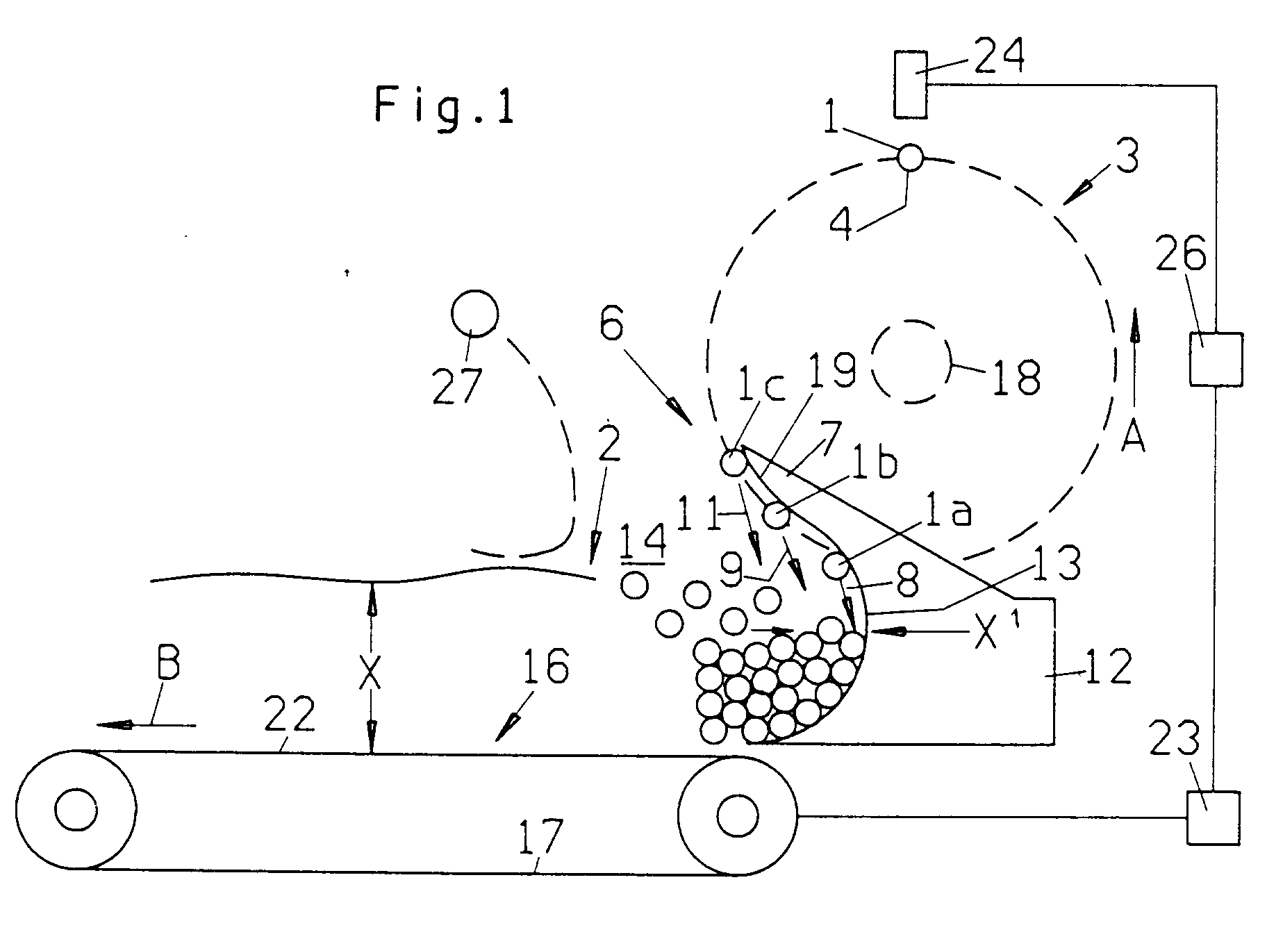
FIG. 1 is a partly schematic side elevational view of an apparatus which can be utilized
for the practice of the improved method and embodies one presently preferred form
of the invention; and
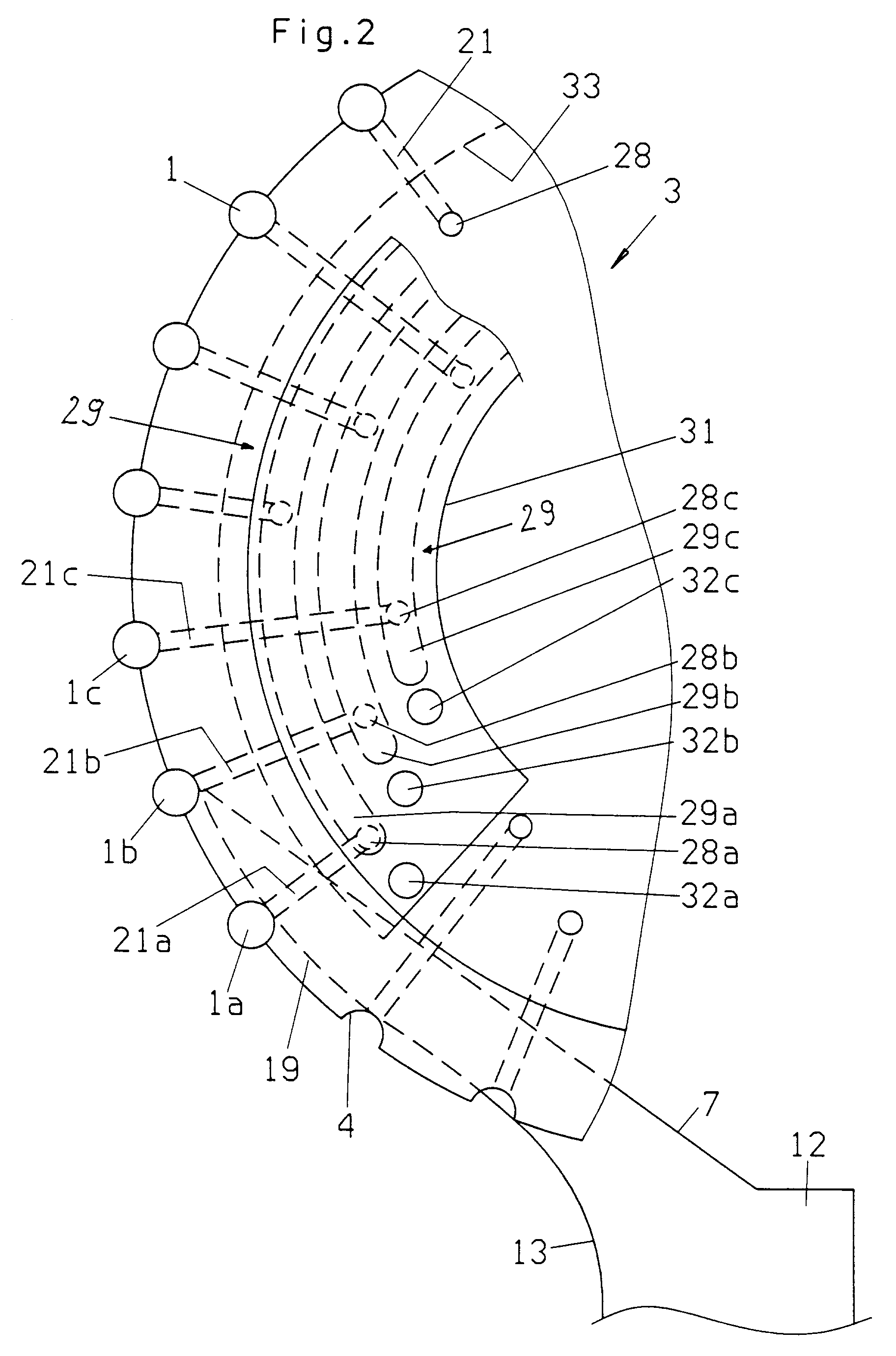
FIG. 2 is an enlarged view of a detail in the apparatus of FIG. 1, showing the construction
of the first conveyor and of the member which diverts successive pluralities of rod-shaped
articles from the advancing means of the first conveyor toward the concave surface
of the intercepting member.
DESCRIPTION OF PREFERRED EMBODIMENTS
[0033] FIG. 1 shows an apparatus which is used to convert a series of successive discrete
elongated rod-shaped articles 1 into a continuous mass flow 2. Successive articles
1 of the series are advanced along a circular first path defined by an array of equidistant
receptacles or advancing means 4 which orbit about the horizontal axis 18 of a rotary
drum-shaped first conveyor 3 when the conveyor is driven to rotate in the direction
of arrow A. The illustrated receptacles 4 are elongated flutes which are machined
into or otherwise formed in the peripheral surface of the conveyor 3. The articles
1 are advanced sideways, i.e., transversely of their length, along the first path
on the conveyor 3 as well during further transport toward and into the mass flow 2.
[0034] The flutes 4 advance successive articles 1 of the series of articles in the first
path toward a transfer station 6 at which successive pluralities or groups of three
articles 1a, 1b, 1c each are diverted into discrete (different or separate) second
paths 8, 9 and 11, respectively. At least one of the three second paths 8, 9 and 11
is at least substantially tangential to the adjacent portion of the first path (extending
along the peripheral surface of the conveyor 1).
[0035] The articles 1a to 1c of each successive plurality or group are diverted in part
by at least one tongue-like diverting member 7 which extends into a circumferentially
complete groove 33 in the peripheral surface of the conveyor 3. The articles 1 which
advance at the transfer station 6 move along the adjacent slightly convex surface
19 of the diverting member 7 which prevents the articles from advancing beyond the
second path 8 on their way toward the concave friction surface 13 which extends across
at least one of the paths 8, 9, 11 and is provided on a stationary intercepting member
12. The illustrated intercepting member is connected to (e.g., of one piece with)
the diverting member 7, and its concave surface 13 establishes a collecting chamber
14 which gathers the intercepted and decelerated articles 1 to form a supply of superimposed
parallel articles.
[0036] The apparatus further comprises a second conveyor 16 including one or more endless
flexible elements 17 (such as belts or chains) serving as a means for withdrawing
from the supply of superimposed articles 1 in the chamber 14 an at least substantially
continuous and uniform mass flow 2 for transport in the direction of arrow B. The
mass flow 2 is advanced by the substantially horizontal upper reach or stretch 22
of the endless flexible element 17.
[0037] The level of the uppermost layer of parallel articles 1 in the mass flow 2 is monitored
by a pivotable sensor lever or arm 27 which can generate signals or which can initiate
the generation of signals serving to regulate the ratio of speeds of the conveyors
3 and 16 when the detected level departs from a desired optimum level. In addition
to or in lieu of such function, the lever or arm 27 can serve as a means for smoothing
the upper side of the mass flow 2 on the conveyor 16.
[0038] A further monitoring device 24 (e.g., a photoelectric detector) is installed adjacent
a portion of the first path at the twelve o'clock position of the conveyor 3 to vary,
at 26, the speed of a variable-speed prime mover 23 for the conveyor 16 when the frequency
of advancement of successive articles 1 past the device 24 is too high or too low,
for example, when the chamber 14 contains an excessive or an insufficient supply of
parallel rod-shaped articles.
[0039] The path which is defined by the convex surface 19 of the diverting or deflecting
member 7 merges gradually into the first path defined by the conveyor 3 as well as
into the additional path which is defined by the concave surface 13 of the intercepting
member 12.
[0040] It will be noted that, in the illustrated apparatus, the conveyor 3 is located at
a first level, that the concave surface 13 is disposed at a second level below the
first level, and that the mass flow 2 leaving the chamber 14 is located at a third
level which is close to or coincides with the second level. The first path which is
defined by the conveyor 3 slopes downwardly toward the transfer station 6, the second
paths 8, 9 and 11 slope downwardly toward the concave surface 13, and the surface
13 slopes downwardly toward the level of the upper reach 22 of the endless flexible
element 17 of the conveyor 16.
[0041] The aforedescribed staggered transfer of pluralities of articles (1a, 1b, 1c) along
different second paths 8, 9 and 11 ensures that the diverted articles 1 are spread
out or fanned out into different portions of the chamber 14, i.e., into different
portions of the supply of superimposed articles 1 in the chamber. Such mode of feeding
articles into the chamber 14 ensures the formation of a homogeneous supply of articles
upstream of the upper reach 22 of the element 17 so that the latter can draw a homogeneous
mass flow 2 toward a processing station, e.g., into a filter tipping machine if the
articles 1 are plain cigarettes, cigars or cigarillos or filter rod sections of unit
length or multiple unit length.
[0042] The concave surface 13 is or can constitute a friction surface which reduces the
kinetic energy of articles 1 coming in direct contact with the intercepting member
12. The concave surface 13 cooperates with the surface 19 and with the pneumatic system
in the conveyor 3 to ensure that the diverted articles as well as the diverted and
intercepted articles penetrate into the lower strata of the articles which form the
supply of superimposed parallel articles in the chamber 14. The height X
1 of the supply of articles 1 in the chamber 14 adjacent the concave surface 13 can
equal or at least approximate the height X of the mass flow 2 on the upper reach 22
of the endless flexible element 17 forming part of the second conveyor 16. The articles
(1c) advancing along the leftmost second path 11 are directed into a loose zone within
the chamber 14, namely into a zone to the left of the layers of articles (1a, 1b)
which were caused to advance along the paths 8 and 9 directly along the concave surface
13. The loose zone in the chamber 14 can be said to constitute a wave hole and is
desirable because this ensures the formation of a supply of parallel articles 1 having
a height which is sufficient to enable the conveyor 16 to withdraw from the chamber
14 an at least substantially uniform or homogeneous mass flow 2 having the desired
height X.
[0043] FIG. 2 illustrates the manner in which the conveyor 3 establishes several second
paths 8, 9 and 11 which make oblique angles with each other, and the manner in which
the conveyor 3 cooperates with the member 12 to ensure the aforediscussed reduction
of kinetic energy of articles 1 advancing toward and into the chamber 14. Each flute
4 of the conveyor 3 is provided with at least one suction port 21 which, in turn,
communicates with one of three axially parallel channels 28 provided in the body of
the conveyor 3. Each channel 28 extends to one end face of the conveyor 3 and communicates,
during a predetermined part of each revolution of the conveyor 3, with one of three
arcuate suction channels 29 provided in a stationary valve plate 31. The grooved or
channeled side of the valve plate 31 is in sealing engagement with the adjacent end
face of the conveyor 3.
[0044] Three successive suction ports 21a, 21b, 21c in the body of the conveyor 3 communicate
with three different grooves 29a, 29b, 29c of the valve plate 31, at least while the
articles 1 are caused to advance along that portion of their first path which is adjacent
the transfer station 6. This ensures that the article 1c of each plurality or group
of articles is no longer attracted to the surface bounding the respective flute 4
and advances along the path 11 while the articles 1b, 1c continue to be held in their
flutes by suction, and that the article 1a of each plurality or group of articles
continues to be attracted to the conveyor 3 while the preceding article 1b is already
in the process of advancing along its path 9.
[0045] The valve plate 31 is further provided with staggered aerating holes or bores 32a,
32b, 32c which respectively admit air into the oncoming channels 28a, 28b, 28c to
thus ensure that the articles 1a, 1b, 1c of successive pluralities or groups are no
longer attracted to the conveyor 3 so that they are even more likely to enter the
respective paths 8, 9 and 11, namely with assistance from centrifugal force.
[0046] The manner in which a rotary drum-shaped conveyor can pneumatically attract rod-shaped
articles during advancement along an arcuate path is fully disclosed and shown, for
example, in U.S. Pat. No. 3,664,891 granted May 23, 1972 to Schubert et al. for "Apparatus
for assembling rows of rod-shaped articles". To the extent that it contributes to
the understanding of the present invention, the disclosure of the patent to Schubert
et al. is incorporated herein by reference.
[0047] The conveyor 3 can form part of or can receive rod-shaped articles from a cigarette
rod making machine such as the cigarette maker known as PROTOS. Alternatively, the
conveyor 3 can form part of or can receive rod-shaped articles from a filter tipping
machine, e.g., a machine known as MAX, or from a filter rod making machine such as
that known as KDF.
[0048] The conveyor 16 can deliver the mass flow 2 to a packing machine, e.g., a machine
known as COMPAS, by way of a transfer system of the type known as RESY or of the type
known as COMFLEX. Alternatively, the conveyor 16 can be utilized to deliver a mass
flow of filter rod sections to a feeding system such as that known as FILTROMAT.
[0049] The aforementioned machines (PROTOS, MAX, KDF and COMPAS) as well as the aforementioned
systems (RESY, COMFLEX and FILTROMAT) are distributed by the assignee of the present
application.
[0050] An important advantage of the improved method and apparatus is that one can dispense
with a top belt, such as that shown in U.S. Pat. No. 4,938,340, for reliable conversion
of a single layer of spaced-apart discrete rod-shaped articles into a homogeneous
mass flow. Furthermore, the improved apparatus is simple and compact and does not
affect the quality of articles on their way from the conveyor 3 onto the conveyor
16. Still further, the concave surface 13 reduces the kinetic energy of oncoming articles
to such an extent that the articles continue to move transversely of their length
and form a stack of parallel articles in the chamber 14 at the receiving end of the
upper reach 22 of the endless flexible element 17. Moreover, the speed of the conveyor
16 can be accurately synchronized with the speed of the conveyor 3 (to produce a mass
flow 2 of desired height) in a simple and inexpensive but reliable manner.
[0051] The number of second paths can be reduced to less than three or increased to more
than three without departing from the spirit of the invention.
[0052] Without further analysis, the foregoing will so fully reveal the gist of the present
invention that others can, by applying current knowledge, readily adapt it for various
applications without omitting features that, from the standpoint of prior art, fairly
constitute essential characteristics of the generic and specific aspects of the above
outlined contribution to the art and, therefore, such adaptations should and are intended
to be comprehended within the meaning and range of equivalence of the appended claims.
1. Apparatus for converting a series of discrete elongated rod-shaped articles (1) of
the tobacco processing industry which are advanced by a rotary conveyor (3) into a
mass flow (2) of superimposed layers of articles (1) which are transported by a second
conveyor (16), characterised in that the rotary conveyor (3) is provided with equidistant
receptacles (4) for advancement of successive discrete articles (1) transversely of
their length along a first path toward a transfer station (6), by the provision of
means (7, 21) for diverting successive pluralities of articles (1a, 1b, 1c) of the
series of articles (1) arriving at the transfer station (6) into a plurality of different
second paths (8, 9, 11), by the provision of means (12) for intercepting successive
pluralities (1a, 1b, 1c) of diverted articles (1) including an at least partially
concave surface (13) extending across at least one (8) of the second paths (8, 9,
11) and establishing a collecting chamber (14) wherein the intercepted articles (1)
gather next to and are superimposed upon each other, and in that the second conveyor
(16) comprises means (17, 22) for withdrawing from the chamber (14) an at least substantially
continuous flow (2) of superimposed articles (1).
2. Apparatus according to Claim 1, characterised in that the rotary conveyor (3) is rotatable
about an axis (18) which is at least substantially parallel to the articles (1) in
the first path and in that the receptacles (4) circulate about the axis (18) of the
rotary conveyor (3) along the first path in response to rotation of the rotary conveyor
(3).
3. Apparatus according to Claim 1 and/or 2, characterized in that the first path is a
partly circular path and at least one of the different second paths (8, 9, 11) is
substantially tangential to the partly circular first path.
4. Apparatus according to at least one of Claims 1 to 3, characterised in that the diverting
means (7, 21) includes means (19, 21) for expelling successive pluralities (1a, 1b,
1c) of articles (1) from the first path into the plurality of different second paths
(8, 9, 11).
5. Apparatus according to Claim 4, characterised in that the diverting means (7, 21)
includes a portion (7, 19) which is connected with the intercepting means (12).
6. Apparatus according to one or more preceding Claims, characterised in that the diverting
means (7, 21) includes a convex surface (19) merging into the at least partially concave
surface (13).
7. Apparatus according to one or more preceding Claims, characterised in that the diverting
means (7, 21) includes means (21) for pneumatically attracting the articles (1) of
the series of articles to the receptacles (4) only along the first path.
8. Apparatus according to Claim 7, characterised in that the means (21, 29) for pneumatically
attacting the articles (1) includes suction ports (21a, 21b, 21c) provided in the
receptacles (4) and means (29a, 29b, 29c) for withdrawing air from the ports (21a,
21b, 21c) during different stages of advancement of successive articles (1a, 1b, 1c)
along the first path so that each article (1) of a plurality of articles (1a, 1b,
1c) is released into the respective second path (8, 9, 11) from a different portion
of the first path.
9. Apparatus according to one or more preceding Claims, characterised in that the rotary
conveyor (3) is disposed at a first level, in that the collecting chamber (14) is
disposed at a second level beneath the first level, and in that the withdrawing means
(17, 22) is disposed at a third level at least close to the second level.
10. Apparatus according to one or more preceding Claims, characterised by the provision
of a variable-speed prime mover (23) for teh second conveyor (16), by the provision
of means (24) for monitoring the frequency of advancement of successive articles (1)
of the series along a portion of the first path, and by the provision of means (26)
for varying the speed of the prime mover (23) as a function of the monitored frequency.
11. Apparatus according to one or more preceding Claims, characterised in that the at
least partially concave surface (13) is a friction surface which decelerates at least
one article (1a) of each plurality of articles (1a, 1b, 1c) on their way into the
collecting chamber (14).
12. Apparatus according to one or more preceding Claims, characterised by the provision
of means (27) for monitoring the height (X) of the flow (2) on the second conveyor
(16).
13. Apparatus according to one or more preceding Claims, characterised in that the rotary
conveyor (3) has a convex peripheral surface extending along the first path and in
that the diverting means (7, 21) has a surface (19) disposed at the transfer station
(6) and establishing for successive pluralities (1a, 1b, 1c) of articles (1) a further
path merging gradually into the first path and into a path defined by the at least
partially concave surface (13).
14. Apparatus according to one or more preceding Claims, characterised in that the receptacles
(4) of the rotary conveyor (3) communicate with suction ports (21) provided in the
rotary conveyor (3).
15. A method of converting a series of successive discrete elongated rod-shaped articles
(1) of the tobacco processing industry into a mass flow (2) of superimposed articles
(1), characterised by advancing successive articles (1) of the series transversely
of their length by a rotary conveyor (3) along a first path toward a transfer station
(6), by diverting successive pluralities (1a, 1b, 1c) of articles (1) of the series
from the first path into a plurality of different second paths (8, 9, 11), by intercepting
successive pluralities (1a, 1b, 1c) of diverted articles (1) including positioning
an at least partially concave surface (13) across at least one (8) of the second paths
(8, 9, 11), by gathering the intercepted articles (1) into a supply (in 14) of superimposed
articles (1), and by drawing (by 16) a continuous mass flow (2) of superimposed articles
(1) from the supply (in 14).
16. Method according to Claim 15, characterised in that the first path includes a substantially
circular portion and in that at least one of the plurality of different second paths
(8, 9, 11) is at least substantially tangential to the circular portion of the first
path.
17. Method according to Claim 15 or 16, characterised in that the second paths (8, 9,
11) are oriented to deliver articles (1) to different portions of the supply (in 14)
of superimposed articles (1).
18. Method according to one or more Claims 15 to 17, characterised in that the at least
partially concave surface (13) is configurated and positioned to reduce the kinetic
energy of at least some (1a) of the articles (1a, 1b, 1c) arriving along the second
paths (8, 9, 11) as a result of frictional engagement between the at least partially
concave surface (13) and the articles (1a).
19. Method according to one or more Claims 15 to 18, characterised in that the rod-shaped
articles (1) are plain or filter cigarettes, cigars or cigarillos and/or filter rod
sections.
20. Method according to one or more Claims 15 to 19, characterised in that the first path
slopes downwardly at the transfer station (6), that the second paths (8, 9, 11) slope
downwardly toward the at least partially concave surface (13), and in that the at
least partially concave surface (13) slopes downwardly toward the supply (in 14) of
superimposed articles (1).
1. Vorrichtung zum Fördern einer Serie von einzelnen, länglichen und stabförmigen Gegenständen
(1) der Tabakverarbeitenden Industrie, die mittels eines drehbaren Förderers (3) in
einen Mengenstrom (2) aus übereinanderliegenden Schichten von Gegenständen (1) bewegt
und die mittels eines zweiten Förderers (16) transportiert werden, dadurch gekennzeichnet,
dass der drehbare Förderer (3) in gleichen Abständen Fächer (4) aufweist, um nacheinander
angeordnete einzelne Gegenstände (1) quer zu ihrer Länge entlang eines ersten Weges
gegen eine Uebergabestation (6) zu bewegen, mit Mitteln (7,21) zum Umlenken aufeinanderfolgender
Mengen von Gegenständen (1a, 1b, 1c) einer Serie von Gegenständen (1), die bei einer
Uebergabestation (6) in einer Mehrzahl von unterschiedlichen zweiten Wegen (8, 9,
11) ankommen, mit Mitteln (12) zum Abscheiden aufeinanderfolgender Mengen (1a, 1b,
1c) umgelenkter Gegenstände (1), die eine wenigstens bereichsweise konkave Fläche
(13) aufweisen, die sich entlang wenigstens eines (8) der zweiten Wege (8, 9, 11)
erstreckt und eine Sammelkammer (14) bildet, wobei die abgeschiedenen Gegenstände
(1) beieinander und übereinander angeordnet sind, und dass der zweite Förderer (16)
Mittel (17, 22) aufweist, um aus der Sammelkammer (14) einen im wesentlichen kontinuierlichen
Fluss (2) aus übereinander angeordneten Gegenständen (1) zu entnehmen.
2. Vorrichtung nach Anspruch 1, dadurch gekennzeichnet, dass der drehbare Förderer (3)
um eine Achse (18) drehbar ist, die im wesentlichen parallel ist zu den Gegenständen
(1) des ersten Weges und dass die Fächer (4) aufgrund der Drehung des drehbaren Förderers
(3) sich entlang eines ersten Weges um die Achse (18) des drehbaren Förderers (3)
bewegen.
3. Vorrichtung nach Anspruch 1 und/oder 2, dadurch gekennzeichnet, dass der erste Weg
teilweise kreisförmig ist und dass wenigstens einer der unterschiedlichen zweiten
Wege (8, 9, 11) im wesentlichen tangential ist zum teilweise kreisförmigen ersten
Weg.
4. Vorrichtung nach wenigstens einem der Ansprüche 1 bis 3, dadurch gekennzeichnet, dass
die Umlenkmittel (7, 21) Mittel (19, 21) aufweisen, um aufeinanderfolgende Mengen
(1a, 1b, 1c) von Gegenständen (1) vom ersten Weg in die mehreren unterschiedlichen
zweiten Wege (8, 9, 11) abzulenken.
5. Vorrichtung nach Anspruch 4, dadurch gekennzeichnet, dass die Umlenkmittel (7, 21)
einen Teil (7,19) aufweisen, welcher mit den abscheidenden Mitteln (12) verbunden
ist.
6. Vorrichtung nach einem oder mehreren der vorausgehenden Ansprüche, dadurch gekennzeichnet,
dass die Umlenkmittel (7, 21) eine konvexe Fläche (19) aufweisen, welche an die wenigstens
teilweise konkave Fläche (13) anschliesst.
7. Vorrichtung nach einem oder mehreren der vorausgehenden Ansprüche, dadurch gekennzeichnet,
dass die Umlenkmittel (7, 21) Mittel (21) aufweisen, um die Gegenstände (1) der Serie
der Gegenstände ausschliesslich entlang des ersten Weges pneumatisch an die Fächer
(4) anzuziehen.
8. Vorrichtung nach Anspruch 7, dadurch gekennzeichnet, dass die Mittel zum pneumatischen
Anziehen der Gegenstände (1) Saugöffnungen (21a, 21b, 21c) aufweisen, die in den Fächern
(4) angeordnet sind, und Mittel (29a, 29b, 29c) vorgesehen sind, um während unterschiedlichen
Bewegungsabschnitten aufeinander folgender Artikel (1a, 1b, 1c) entlang des ersten
Weges Luft aus den Saugöffnungen abzuziehen, sodass jeder Artikel (1) einer Mehrzahl
von Artikeln (1a, 1b, 1c) aus unterschiedlichen Abschnitten des ersten Weges in einen
entsprechenden zweiten Weg (8, 9, 11) freigegeben wird.
9. Vorrichtung nach einem der vorhergehenden Ansprüche, dadurch gekennzeichnet, dass
der drehbare Förderer (1) auf einem ersten Niveau angeordnet ist, dass die Sammelkammer
(14) auf einen zweiten Niveau unterhalb des ersten Niveaus angeordnet ist und dass
die Abtransportmittel (17, 22) auf einen dritten Niveau wenigstens nahe des zweiten
Niveaus angeordnet sind.
10. Vorrichtung nach einem der vorhergehenden Ansprüche, dadurch gekennzeichnet, dass
für den zweiten Förderer (16) ein geschwindigkeitsvariabler erster Antrieb (23) vorgesehen
ist, dass Mittel (24) zum Überwachen der Förderfrequenz aufeinander folgender Gegenstände
(1) der Serie entlang eines Abschnittes des ersten Weges und dass Mittel (26) vorgesehen
sind, um die Geschwindigkeit des ersten Antriebs (23) als eine Funktion der überwachten
Frequenz zu ändern.
11. Vorrichtung nach einem oder mehreren der vorausgehenden Ansprüche, dadurch gekennzeichnet,
dass die wenigstens bereichsweise konkrave Fläche (13) eine Reibungsfläche ist, welche
wenigstens einen Gegenstand (1a) jeder Gegenstandsmenge (1a, 1b, 1c) auf seinem Weg
in die Sammelkammer (14)bremst.
12. Vorrichtung nach einem oder mehreren der vorausgehenden Ansprüche, dadurch gekennzeichnet,
dass Mittel (27) vorgesehen sind, um die Höhe (X) des Flusses (2) auf dem zweiten
Förderer (16) zu überprüfen.
13. Vorrichtung nach einem oder mehreren der vorausgehenden Ansprüche, dadurch gekennzeichnet,
dass der drehbare Förderer (3) eine konvexe periphere Fläche aufweist, die sich entlang
des ersten Weges erstreckt und dass die Umlenkmittel (7, 21) eine Fläche (19) aufweisen,
die bei der Uebergabestation (6) angeordnet ist und die für aufeinanderfolgende Mengen
(1a, 1b, 1c) von Gegenständen (1) einen weiteren Weg bilden der allmählich in den
ersten Weg und in einen Weg übergeht, der durch die wenigstens teilweise konkrave
Fläche (13) gebildet wird.
14. Vorrichtung nach einem oder mehreren der vorausgehenden Ansprüche, dadurch gekennzeichnet,
dass die Fächer (4) des drehbaren Förderers (3) mit den Saugöffnungen verbunden sind,
welchen im drehbaren Förder (3) angeordnet sind.
15. Verfahren zum Fördern einer Serie aufeinander folgender einzelner und stabförmiger
Gegenstände (1) der Tabakverarbeitenden Industrie in einen Mengenstrom (2) aus übereinander
liegender Gegenstände (1), dadurch gekennzeichnet, dass aufeinander folgende Gegenstände
(1) der Serie quer zu ihrer Länge mit einem drehbaren Förderer (3) entlang eines ersten
Weges gegen eine Uebergabestation (6) bewegt werden, dass aufeinander folgende Mengen
(1a, 1b, 1c) von Gegenständen (1) der Serie von einem ersten Weg in eine Mehrzahl
von unterschiedlichen zweiten Wegen (8, 9, 11) umgelenkt werden, dass aufeinander
folgende Mengen (1a, 1b, 1c) der umgelenkten Gegenstände (1) an wenigstens einer teilweise
konkraven Fläche (13) entlang wenigstens eines (8) der zweiten Wege (8, 9, 11) abgeschieden
werden, wobei die abgeschiedenen Gegenstände (1) zu einem Zufluss (bei 14) von übereinander
angeordneten Gegenständen (1) gesammelt werden, und wobei ein kontinuierlicher Mengenstrom
(2) von übereinander angeordneten Artikeln (1) vom Zufluss (bei 14) abgezogen wird.
16. Verfahren nach Anspruch 15, dadurch gekennzeichnet, dass der erste Weg einen im wesentlichen
kreisförmigen Bereich aufweist und dass wenigstens einer der mehreren unterschiedlichen
zweiten Wege (8, 9, 11) im wesentlichen tangenzial zum kreisförmigen Bereich des ersten
Weges ist.
17. Verfahren nach Anspruch 15 oder 16, dadurch gekennzeichnet, dass die zweiten Wege
(8, 9, 11) so ausgerichtet sind, dass Gegenstände (1) zu unterschiedlichen Bereichen
des Zuflusses (bei 14) aus übereinander angeordneten Gegenständen (1) abgegeben werden.
18. Verfahren nach einem oder mehreren der Ansprüche 15 bis 17, dadurch gekennzeichnet,
dass die wenigstens bereichsweise konkrave Fläche (13) so ausgebildet und angeordnet
ist, dass die kinetische Energie wenigstens einiger (1a) der Gegenstände (1a, 1b,
1c) als Resultat einer Reibung zwischen der wenigstens bereichsweise konkraven Fläche
(13) und der Gegenstände (1a) entlang der zweiten Wege (8, 9, 11) reduziert ist.
19. Verfahren nach einem oder mehreren der Ansprüche 15 bis 18, dadurch gekennzeichnet,
dass die stabförmigen Gegenstände (1) filterlose Zigaretten oder Filterzigaretten,
Zigarren oder Zigarillos und/oder Filterstababschnitte sind.
20. Verfahren nach einem oder mehreren der Ansprüche 15 bis 19, dadurch gekennzeichnet,
dass der erste Weg bei der Uebergabestation (6) nach unten geneigt ist, dass die zweiten
Wege (8, 9, 11) nach unten gegen die wenigstens bereichsweise konkrave Fläche (13)
geneigt sind, und dass die wenigstens bereichsweise konkrave Fläche (13) nach unten
gegen den Zufluss (bei 14) der übereinander angeordneten Artikel (1) geneigt ist.
1. Dispositif pour convertir une série d'articles allongés séparés en forme de tiges
(1) de l'industrie de transformation du tabac, qu'un transporteur rotatif (3) fait
avancer, en un flux massique (2) de couches superposées d'articles (1), qui sont transportées
par un second transporteur (16), caractérisé en ce que le transporteur rotatif (3)
comporte des réceptacles équidistants (4) pour faire avancer des articles séparés
successifs (1) dans une direction transversale à leur longueur, le long d'un premier
trajet dirigé vers un poste de transfert (6), en ce qu'il est prévu des moyens (7,
21) pour dévier des ensembles successifs d'articles (1a, 1b, 1c) de la série d'articles
(1), arrivant au poste de transfert (6), sur une pluralité de seconds trajets différents
(8, 9, 11), en ce qu'il est prévu des moyens (12) pour intercepter des ensembles successifs
(1a, 1b, 1c) d'articles déviés (1), comprenant une surface au moins partiellement
concave (13) s'étendant en travers d'au moins l'un (8) des seconds trajets (8, 9,
11) et établissant une chambre collectrice (14), dans laquelle les articles interceptés
(1) se regroupent les uns avec les autres et sont superposés les uns aux autres, et
en ce que le second transporteur (16) comprend des moyens (17, 22) pour extraire de
la chambre (14) un flux au moins sensiblement continu (2) d'articles superposés (1).
2. Dispositif selon la revendication 1, caractérisé en ce que le transporteur rotatif
(3) peut tourner autour d'un axe (18) qui est parallèle, au moins sensiblement, aux
articles (1) situés dans le premier trajet et en ce que les réceptacles (4) circulent
autour de l'axe (18) du transporteur rotatif (3) le long du premier trajet suite à
la rotation du transporteur rotatif (3).
3. Dispositif selon la revendication 1 et/ou 2, caractérisé en ce que le premier trajet
est un trajet partiellement circulaire et l'un au moins des seconds trajets différents
(8, 9, 11) est sensiblement tangent au premier trajet partiellement circulaire.
4. Dispositif selon au moins l'une des revendications 1 à 3, caractérisé en ce que les
moyens de déviation (7, 21) comprennent des moyens (19, 21) pour éjecter des ensembles
successifs (1a, 1b, 1c) d'articles (1) du premier trajet pour les introduire dans
la pluralité de seconds trajets différents (8, 9, 11).
5. Dispositif selon la revendication 4, caractérisé en ce que les moyens de déviation
(7, 21) comprennent une partie (7, 19) qui est raccordée aux moyens d'interception
(12).
6. Dispositif selon une ou plusieurs des revendications précédentes, caractérisé en ce
que les moyens de déviation (7, 21) comprennent une surface convexe (19) qui se prolonge
par la surface au moins partiellement concave (13).
7. Dispositif selon une ou plusieurs des revendications précédentes, caractérisé en ce
que les moyens de déviation (7, 21) comprennent des moyens (21) pour réaliser une
attraction pneumatique des articles (1) de la série d'articles sur les réceptacles
(4), uniquement le long du premier trajet.
8. Dispositif selon la revendication 7, caractérisé en ce que les moyens (21, 29) d'attraction
pneumatique des articles (1) comprennent des orifices d'aspiration (21a, 21b, 21c)
prévus dans les réceptacles (4) et des moyens (29a, 29b, 29c) pour extraire de l'air
des orifices (21a, 21b, 21c) pendant des phases d'avance différentes d'articles successifs
(1a, 1b, 1c) le long du premier trajet, de sorte que chaque article (1) d'un ensemble
d'articles (1a, 1b, 1c) est libéré dans le second trajet respectif (8, 9, 11) depuis
une partie différente du premier trajet.
9. Dispositif selon une ou plusieurs des revendications précédentes, caractérisé en ce
que le transporteur rotatif (3) est disposé à un premier niveau, en ce que la chambre
collectrice (14) est disposée à un second niveau en dessous du premier niveau et en
ce que les moyens d'extraction (17, 22) sont disposés à un troisième niveau, au moins
proche du second niveau.
10. Dispositif selon une ou plusieurs des revendications précédentes, caractérisé en ce
qu'il est prévu une machine motrice (23) à vitesse variable pour le second transporteur
(16), en ce qu'il est prévu des moyens (24) pour contrôler la fréquence d'avance d'articles
successifs (1) de la série le long d'une partie du premier trajet, et en ce qu'il
est prévu des moyens (26) pour modifier la vitesse de la machine motrice (23) en fonction
de la fréquence contrôlée.
11. Dispositif selon une ou plusieurs des revendications précédentes, caractérisé en ce
que la surface au moins partiellement concave (13) est une surface de friction qui
décélère au moins un article (1a) de chaque ensemble d'articles (1a, 1b, 1c) sur le
trajet qui les mène dans la chambre collectrice (14).
12. Dispositif selon une ou plusieurs des revendications précédentes, caractérisé en ce
qu'il est prévu des moyens (27) pour contrôler la hauteur (X) du flux (2) sur le second
transporteur (16).
13. Dispositif selon une ou plusieurs des revendications précédentes, caractérisé en ce
que le transporteur rotatif (3) possède une surface périphérique convexe, qui s'étend
le long du premier trajet, et en ce que les moyens de déviation (7, 21) possèdent
une surface (19) disposée au poste de transfert (6) et établissant, pour des ensembles
successifs (1a, 1b, 1c) d'articles (1) un trajet supplémentaire qui rejoint progressivement
le premier trajet et un trajet défini par la surface au moins partiellement concave
(13).
14. Dispositif selon une ou plusieurs des revendications précédentes, caractérisé en ce
que les réceptacles (4) du transporteur rotatif (3) communiquent avec des orifices
d'aspiration (21) prévus dans le transporteur rotatif (3).
15. Procédé pour convertir une série d'articles successifs allongés séparés en forme de
tiges (1) de l'industrie de transformation du tabac, en un flux massique (2) d'articles
superposés (1), caractérisé par l'avancement des articles successifs (1) de la série
dans une direction transversale à leur longueur au moyen d'un transporteur rotatif
(3), le long d'un premier trajet dirigé vers un poste de transfert (6), par la déviation
des ensembles successifs (1a, 1b, 1c) d'articles (1) de la série du premier trajet
sur une pluralité de seconds trajets différents (8, 9, 11) par l'interception d'ensembles
successifs (1a, 1b, 1c) d'articles déviés (1) faisant intervenir le positionnement
d'une surface au moins partiellement concave (13) en travers d'au moins l'un (8) des
seconds trajets (8, 9, 11), par le regroupement des articles interceptés (1) en une
réserve (en 14) d'articles superposés (1), et par l'extraction (en 16) d'un flux massique
continu (2) d'articles superposés (1) de la réserve (en 14).
16. Procédé selon la revendication 15, caractérisé en ce que le premier trajet comprend
une partie essentiellement circulaire et en ce qu'au moins l'un des seconds trajets
différents (8, 9, 11) est au moins sensiblement tangent à la partie circulaire du
premier trajet.
17. Procédé selon la revendication 15 ou 16, caractérisé en ce que les seconds trajets
(8, 9, 11) sont orientés de manière à délivrer des articles (1) à des parties différentes
de la réserve (en 14) d'articles superposés (1).
18. Procédé selon une ou plusieurs des revendications 15 à 17, caractérisé en ce que la
surface au moins partiellement concave (13) est configurée et positionnée de manière
à réduire l'énergie cinétique d'au moins certains (1a) des articles (1a, 1b, 1c) arrivant
le long des seconds trajets (8, 9, 11), par suite d'un contact avec friction entre
la surface au moins partiellement concave (13) et les articles (1a).
19. Procédé selon une ou plusieurs des revendications 15 à 18, caractérisé en ce que les
articles en forme de tiges (1) sont des cigarettes sans filtre ou avec filtre, des
cigares ou des cigarillos et/ou des tronçons de tiges de filtre.
20. Procédé selon une ou plusieurs des revendications 15 à 19, caractérisé en ce que le
premier trajet s'incline vers le bas au poste de transfert (6), en ce que les seconds
trajets (8, 9, 11) s'inclinent vers le bas en direction de la surface au moins partiellement
concave (13) et en ce que la surface au moins partiellement concave (13) s'incline
vers le bas en direction de la réserve (en 14) d'articles superposés (1).