| (19) |
 |
|
(11) |
EP 0 715 027 B1 |
| (12) |
EUROPEAN PATENT SPECIFICATION |
| (45) |
Mention of the grant of the patent: |
|
03.09.1997 Bulletin 1997/36 |
| (22) |
Date of filing: 16.06.1995 |
|
| (51) |
International Patent Classification (IPC)6: E02D 13/06 |
|
| (54) |
A method for driving a sheet pile wall
Verfahren zum Eintreiben einer Spundbohlenwand
Méthode pour former une paroi de palplanches par enfoncement
|
| (84) |
Designated Contracting States: |
|
BE DE FR GB IT NL |
| (30) |
Priority: |
02.12.1994 NL 9402032
|
| (43) |
Date of publication of application: |
|
05.06.1996 Bulletin 1996/23 |
| (73) |
Proprietor: van Halteren, Tijmen |
|
NL-3751 ET Bunschoten (NL) |
|
| (72) |
Inventor: |
|
- van Halteren, Tijmen
NL-3751 ET Bunschoten (NL)
|
| (74) |
Representative: Boelsma, Gerben Harm, Ir. |
|
van Exter Polak & Charlouis B.V.,
P.O. Box 3241
2280 GE Rijswijk
2280 GE Rijswijk (NL) |
| (56) |
References cited: :
NL-A- 7 908 262
|
NL-A- 9 102 123
|
|
| |
|
|
|
|
| |
|
| Note: Within nine months from the publication of the mention of the grant of the European
patent, any person may give notice to the European Patent Office of opposition to
the European patent
granted. Notice of opposition shall be filed in a written reasoned statement. It shall
not be deemed to
have been filed until the opposition fee has been paid. (Art. 99(1) European Patent
Convention).
|
[0001] The invention relates to a method for driving a sheet pile wall as defined in the
first part of claim 1.
[0002] Such a method is known from NL-A-7908262. The detection pin used therein is in the
form of a bolt having an enlarged foot that bears on the lower edge of the sheet pile
portion surrounding the lock space. The detection line is fastened laterally to said
enlarged foot.
[0003] The invention provides a method of the type above referred to which distinguishes
from the well-known method by the features of the second part of claim 1.
[0004] The invention also relates to a sheet pile for use with the above method, said sheet
pile having the features as defined in claim 3.
[0005] The invention will be hereinafter further described by way of example with reference
to the accompanying drawing.
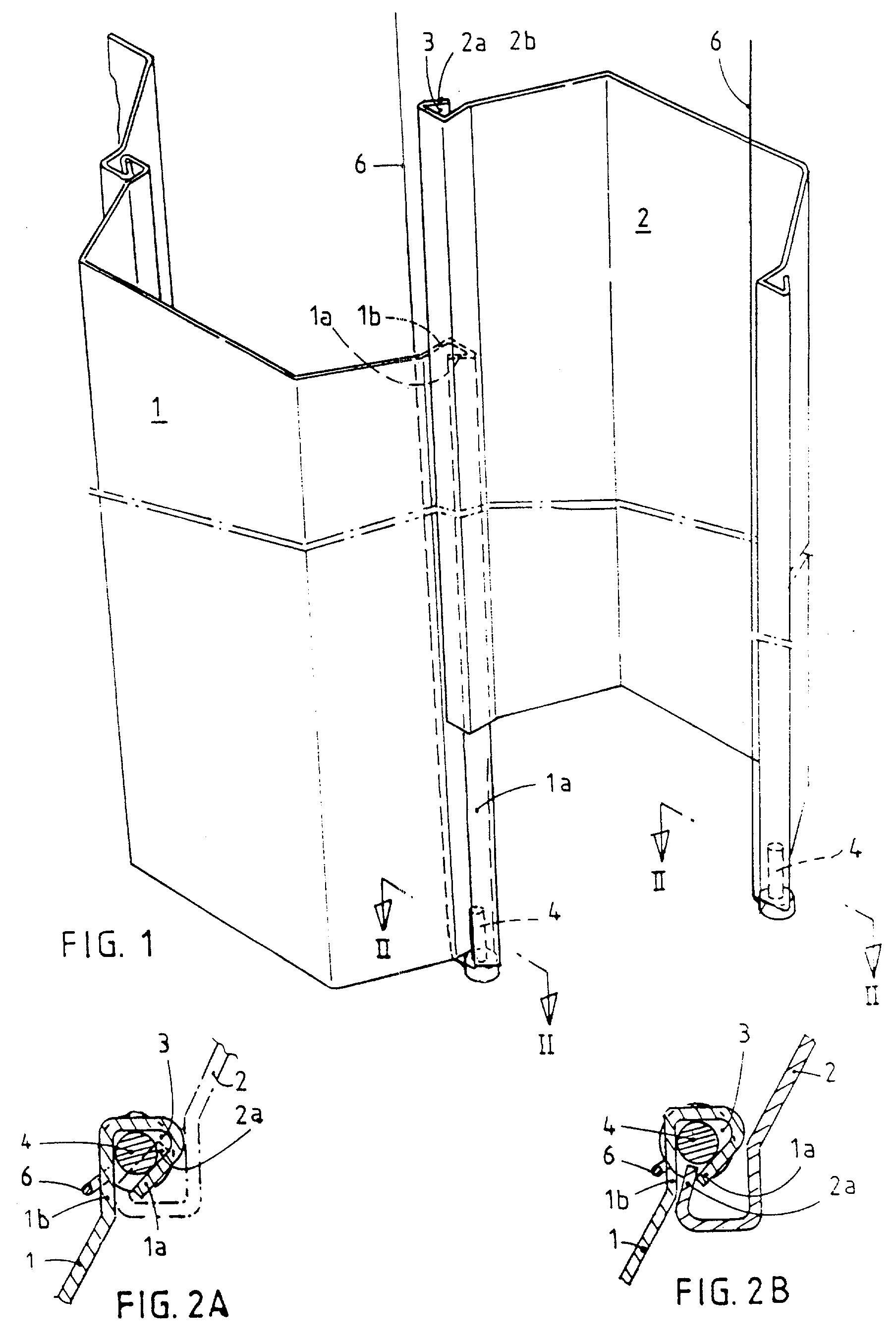
Fig. 1 is a perspective view showing how two adjacent sheet piles are entering into
mutual engagement, wherein a detection pin of a known type is used;
fig. 2A is a cross-sectional view, along the line II-II in fig. 1, in which a second
sheet pile, that "runs in the lock", is indicated by dash-dotted lines;
fig. 2B is a cross-section as shown in fig. 2A, in which dash-dotted lines designate
a second sheet pile, which is about to "run out of the lock";
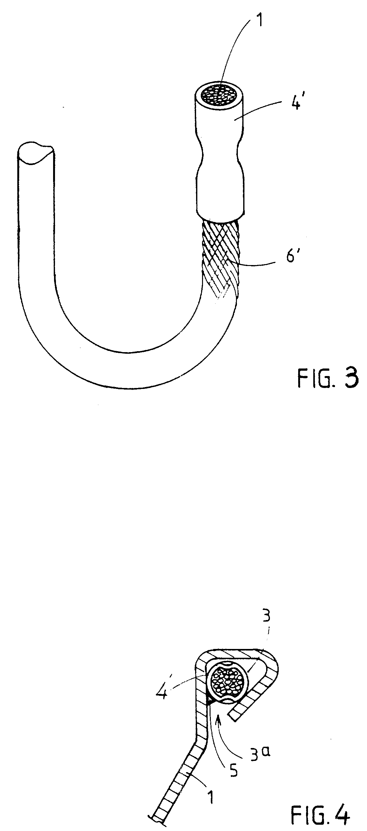
fig. 3 is a perspective view of a detection pin according to the invention, in the
form of a sleeve that is clamped on the end of a steel wire cable, said detection
pin being intended to be used as a substitution for the detection pin shown in fig.
1; and
fig. 4 is a cross-section through the lower end of a sheet pile and a detection pin
of fig. 3 inserted therein.
[0006] In fig. 1 two trapezium-shaped sheet piles of a well-known design are illustrated
in a diagrammatic manner and indicated by the reference number 1 and 2; the sheet
pile 1 has already been driven to the desired depth into the ground, whereas the sheet
pile 2 has to be driven further.
[0007] The sheet piles 1 and 2 have their longitudinal edges la and 2a respectively in mutual
engagement in a well-known manner.
[0008] Along the free longitudinal edge la of the sheet pile 1, i.e. the longitudinal edge,
which has to be brought into engagement with the adjacent longitudinal edge 2a of
the next sheet pile 2 to be driven, there is provided a "lock space" 3. In the lower
end of this lock space, which has a substantially triangular cross-section, a detection
pin 4 is inserted and a detection line 6 is anchored in the lower end face of the
pin 4. The detection line extends upwardly along the outer side of the lock space
wall 1b (fig. 2). The detection pin 4 shown in fig. 1 is of a type according to the
prior art above referred to. The detection pin according to the invention, which is
intended to be substituted for the detection pin 4 in fig. 1, is shown in fig. 3 and
4 and is in the form of a metal sleeve 4' which is clamped on the distal end of a
steel wire cable 6' functioning as a detection line. This sleeve 4' may be readily
clamped onto the cable 6' by means of a simple clamping tool and is secured in the
lock space 3 by means of one or more tack welds 5, which are provided via the lock
space slit 3a.
[0009] Fig. 2A illustrates the case, in which the sheet pile 2 is "properly engaged" and
will - while driving is continued - get with the lower end of its longitudinal edge
2a in engagement with the upper end of the detection pin 4 (4') as a result of which
the latter will be finally expelled from the lower end of the lock space 3 of the
pile sheet 1, while the tack weld(s) 5 are broken off. This situation can be observed
above ground through the detection line 6 becoming slack.
[0010] Fig. 2B illustrates the case, in which the sheet pile 2 has partially "run out of
the lock" and will - while continuing driving - remain just out of engagement with
the detection pin 4 (4'), as a result of which the latter will remain within the lower
end of the lock space 3 of the last driven sheet pile 1.
[0011] This situation can be observed aboveground through the detection line 6 being kept
tensioned.
[0012] In the event the second sheet pile to be driven has a shorter length than the first
driven sheet pile 1, so that the lower end of the second sheet pile will not reach
the detection pin within the lock space of the driven sheet pile, the difference in
length may be compensated by a filling rod of a corresponding length which is dropped
into the lock space of the driven sheet pile.
1. A method for driving a sheet pile wall by successively driving sheet piles (1, 2),
of which the profiled longitudinal edges (1a; 2a) are slidingly engaging one another,
into the ground, wherein sheet piles (1, 2) are driven, which are provided below,
at the free longitudinal edge (1a; 2a), with a detection pin (4') inserted axially
from below into a lock space (3) confined by said longitudinal edge (1a; 2a), the
lower end of said pin (4') being connected to a detection line (6') extending upwardly
along the outer side of the lock space (3), characterized in that use is made of a
detection pin in the form of a sleeve (4') that is clamped on the distal end of a
steel wire cable (6') functioning as a detection line, said sleeve (4') being secured
in the lock space (3) by a break-connection (5).
2. A method according to claim 1, characterized in that the break-connection is effected
by providing one or more tack welds (5).
3. Sheet pile, the profiled longitudinal edges (1a; 2a) of which confine a lock space
(3) for engagement with the longitudinal edge (2a; 1a) of an adjacent sheet pile,
a detection pin (4') being axially inserted within the lower end of the lock space
(3) along one of the longitudinal edges (la; 2a), said detection pin (4') having its
lower end connected to a detection line (6'), characterized in that use is made of
a detection pin in the form of a sleeve (4) that is clamped on the distal end of a
steel wire cable (6') functioning as a detection line, said sleeve (4') being secured
in the lock space (3) by one or more tack welds (5).
1. Verfahren zum Eintreiben einer Spundbohlenwand, indem aufeinanderfolgend Spundbohlen
(1, 2) in den Boden eingetrieben werden, deren profilierte Längskanten (1a; 2a) gleitend
ineinandergreifen, wobei Spundbohlen (1, 2) verwendet werden, die unten an der freien
Längskante (1a; 2a) mit einem achsial von unten in den von der Längskante (1a; 2a)
begrenzten Schlossraum (3) gesteckten Überwachungsbolzen (4') versehen sind, von welchem
Bolzen (4') das untere Ende mit einer an der Aussenseite des Schlossraumes (3) entlang
nach oben laufenden Überwachungsleine (6') verbunden ist, dadurch gekennzeichnet,
dass ein Überwachungsbolzen in Form einer auf dem unteren Ende eines als Überwachungsleine
funktionierenden Drahtseils (6') geklemmten Buchse (4') verwendet wird, welche Buchse
(4') im Schlossraum (3) durch eine Sollbruchverbindung (5') gehalten wird.
2. Verfahren nach Anspruch 1, dadurch gekennzeichnet, dass die Sollbruchverbindung durch
eine oder mehrere Heftschweissungen gebildet wird.
3. Spundbohle, deren profilierte Längskanten (la; 2a) einen Schlossraum (3) zum Eingriff
mit der Längskante (2a; 1a) einer angrenzenden Spundbohle begrenzen, wobei ein Überwachungsbolzen
(4') in achsialer Richtung in das untere Ende des Schlossraumes (3) an einer der Längskanten
(1a; 2a) gesteckt ist, welcher Überwachungsbolzen (4') mit seinem unteren Ende mit
einer Überwachungsleine (6') verbunden ist, dadurch gekennzeichnet, dass ein Überwachungsbolzen
in Form einer auf dem unteren Ende eines als Überwachungsleine funktionierenden Drahtseils
(6') geklemmten Buchse (4) verwendet wird, welche Buchse (4') mittels einer oder mehrerer
Heftschweissungen (5) im Schlossraum (3) fixiert ist.
1. Procédé d'entraînement d'une paroi de palplanches, par entraînement successif de palplanches
(1, 2) dont les bords longitudinaux (1a; 2a) profilés s'engagent par coulissement
les uns contre les autres, dans le sol, dans lequel les palplanches (1, 2) sont entraînées,
palplanches pourvues, en partie inférieure, au niveau du bord longitudinal (1a; 2a)
libre, d'une tige de détection (4') insérée axialement par le dessous dans un espace
de verrouillage (3) confiné par ledit bord longitudinal (1a; 2a), l'extrémité inférieure
de ladite tige (4') étant reliée à un câble de détection (6') s'étendant vers le haut
le long du côté extérieur de l'espace de verrouillage (3), caractérisé en ce que l'on
utilise une tige de détection se présentant sous la forme d'un manchon (4') qui est
serré sur l'extrémité distale d'un câble de fil d'acier (6') servant de câble de détection,
ledit manchon (4') étant fixé dans l'espace de verrouillage (3) au moyen d'une connexion
à rupture (5).
2. Procédé selon la revendication 1, caractérisé en ce que la connexion à rupture est
réalisée en effectuant une ou plusieurs soudures par points (5).
3. Palplanche, dont les bords longitudinaux (1a; 2a) profilés confinent un espace de
verrouillage (3) destiné à l'engagement contre le bord longitudinal (2a; 1a) d'une
palplanche adjacente, une tige de détection (4') étant insérée axialement dans l'extrémité
inférieure de l'espace de verrouillage (3) le long de l'un des bords longitudinaux
(1a; 2a), ladite tige de détection (4') ayant son extrémité inférieure reliée à un
câble de détection (6'), caractérisée en ce que l'on utilise une tige de détection
se présentant sous la forme d'un manchon (4) qui est serré sur l'extrémité distale
d'un câble de fil d'acier (6') servant de câble de détection, ledit manchon (4') étant
fixé dans l'espace de verrouillage (3) par une ou plusieurs soudures par points (5).