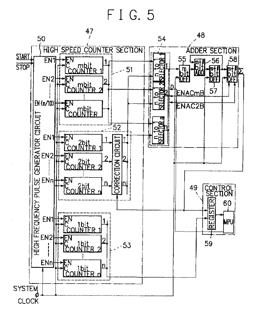
(57) A time interval measurement system, by which measurement of individual time interval
with remarkably improved measurement accuracy is made possible with smaller circuit
scale, comprises a high speed counter section, an adder section, and a control section.
The high speed counter section includes a m-bit counter unit having a plurality of
m-bit counters for obtaining an integer part of the time interval between a START
signal and a STOP signal, a first 1-bit counter unit having a plurality of first 1-bit
counters for obtaining an decimal part of the time interval, and a high frequency
pulse generator circuit. The high frequency pulse generator circuit periodically generates
a plurality of delayed signals at intervals of a unit delay time which is shorter
than the cycle time of the clock signal, according to the input of the START signal
to the high speed counter section, and supplies each of a plurality of counter stop
signals according to the delayed signals to a corresponding m-bit counter in the m-bit
counter unit and a corresponding first 1-bit counter in the first 1-bit counter unit.
In order to use the first 1-bit counters (not 2-bit counters) for obtaining the decimal
part of the time interval, the first 1-bit counter unit is provided with a first correction
circuit and a second correction circuit. The first correction circuit executes +1
correction to the counted values of the first 1-bit counters according to detection
of a carry. The second correction circuit executes +2 correction to the counted values
of the first 1-bit counters according to detection of ' return to an initial value'.
|
|
