(57) A sliding door assembly comprises a sliding door, a track (100) underneath the sliding
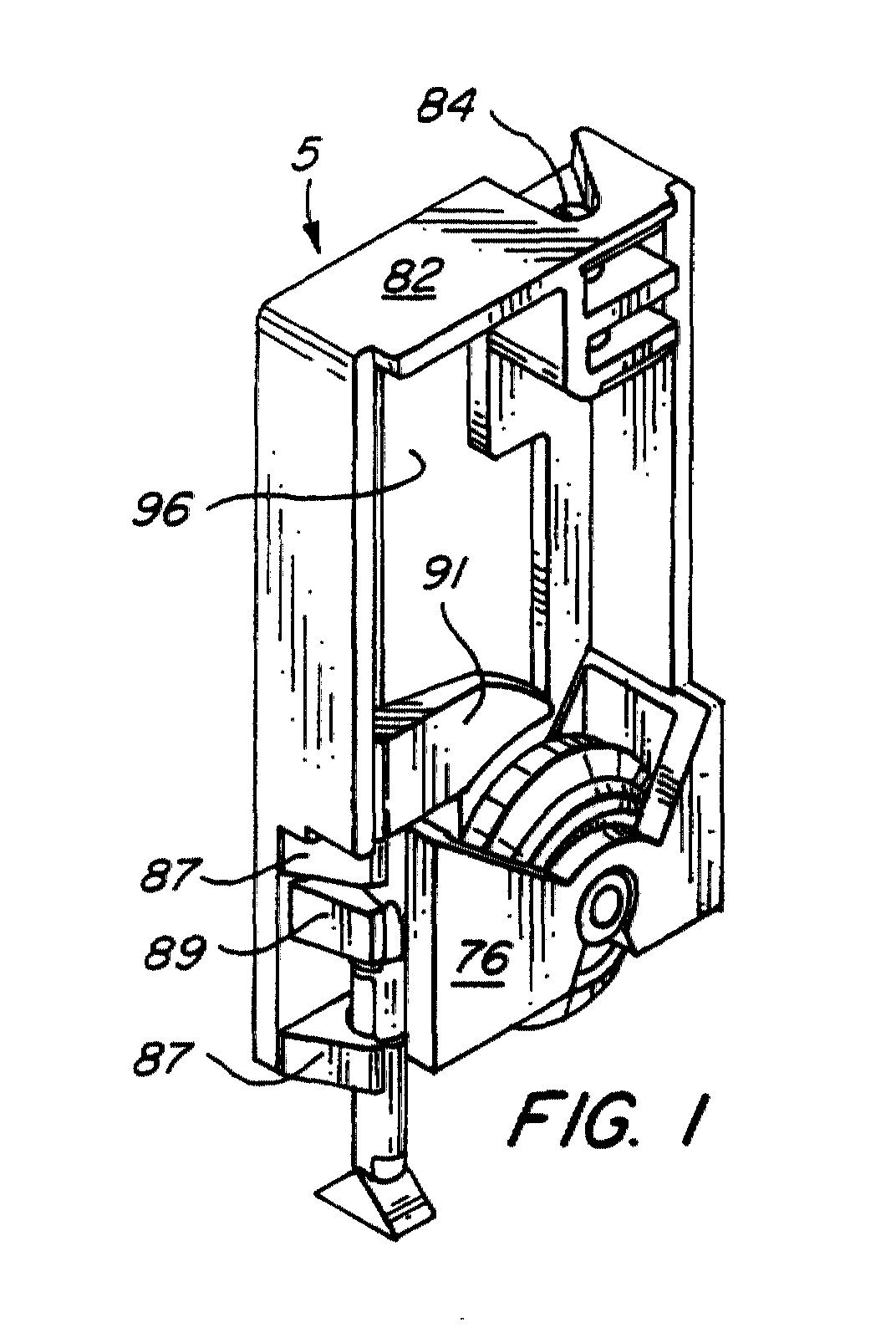
door, and a roller assembly (1). The roller assembly (1) comprises:- a bracket (3)
attached to the door at or near the bottom of the door, the bracket (3) having a generally
planar body portion (24); a roller mounting member (5) slidably seated in said bracket
(3), the roller mounting member (5) having first and second side walls (76, 78) extending
generally parallel to the plane of said bracket body portion (24); and a roller (7)
rotatably mounted on said roller mounting member (5) for travel along the track (100).
The roller (7) is disposed between said first and second side walls (76, 78) and rotates
about an axis perpendicular to the plane of the bracket body portion (24). The roller
(7) has a rim (7a) and a median plane generally parallel to the plane of the bracket
body portion (24). A vertically and rotatably displaceable anti-jump member (9) is
engageable with the track (100) to prevent the roller (7) from derailing. The anti-jump
member (9) comprises a handle (91) adjacent an upper end of said anti-jump member
(9), an elongate shaft (93) extending downwardly from the handle (91), and an enlarged
track engagement portion (95) at a lower end of the anti-jump member (9). The anti-jump
member (9) is disposed with the shaft (93) lying in the median plane of the roller
(7) and adjacent the roller rim (7a). The anti-jump member (9) is carried by the roller
mounting member (5), for vertical displacement between a lowered position wherein
said engagement portion (95) can engage and disengage the track (100), and a raised
position wherein said engagement portion (95) is spaced upwardly from said track (100),
and for rotative displacement in the lowered position. The roller (7) comprises a
wheel (7') having a circular central portion forming said rim (7a) and flanked by
two co-axial circular side portions (7b, 7c) of smaller diameter than said central
portion (7a). The track (100) is formed with two shoulders (204, 206) on either side
of a central cavity (208), the two shoulders (204, 206) being situated at the top
of the track (100). The roller (7) runs on the track (100) by virtue of the two side
portions (7b, 7c) thereof running on the two shoulders (204, 206). The open top of
the central cavity (208) forms a slot, level with the two shoulders (204, 206), and
the central cavity (208) widens out below the two, overhanging, shoulders (204, 206).
The central portion of the roller (7) extends through the slot and below the level
of the two shoulders (204, 206) into the central cavity (208). The anti-jump member
(9), when lowered, is selectively rotatable to an operative position and to an inoperative
position such that, in the operative position of the anti-jump member (9), the shoulders
(204, 206) of the track (100) overhang parts of said track engagement portion (95),
so that the track engagement portion (95) cannot be withdrawn from the track (100),
and such that, in the inoperative position of the anti-jump member (9), the shoulders
(204, 206) of the track (100) overhang no part of said track engagement portion (95),
so that the track engagement portion (95) can be displaced vertically, to be selectively
inserted into or withdrawn from the track (100) through the slot. The door is able
to slide, supported and guided on the track (100) by the roller assembly (1), with
the anti-jump member (9) in any of said raised and lowered positions. The roller assembly
(1) is thus restrained from jumping off the track (100) with the anti-jump member
(9) lowered and rotated to its operative position.
|
|
