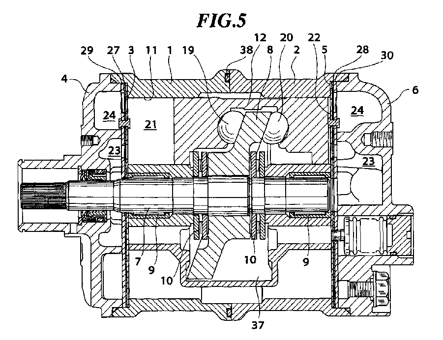
(57) A reciprocating compressor comprises a cylinder block (1,2) having a plurality of
compression chambers (21,22) formed therein and on at least one of opposite ends of
respective pistons (12) slidably received within respective cylinder bores (11). A
cylinder head (4,6) is secured to the cylinder block (1,2) and has a high-pressure
chamber (24) and a low-pressure chamber (23) formed therein. A separating member is
arranged between the cylinder block (1,2) and the cylinder head (4,6) and has a valve
sheet (27,28), a valve plate (3,5) and a stopper plate (29,30). The valve sheet (27,28)
is formed with suction valves (27d,28d) and discharge valves (27a,28a). The valve
plate (3,5) is arranged between the valve sheet (27,28) and the cylinder block (1,2)
and is formed with refrigerant outlet ports (3a,5a) and a plurality of relief holes
(3b,5b) each opening into a corresponding one of the compression chambers (21,22)
for communicating with a corresponding one of refrigerant inlet ports (29d,30d) formed
through the stopper plate (29,30) when a corresponding one of the suction valves (27d,28d)
opens. The stopper plate (29,30) is arranged between the valve sheet (27,28) and the
cylinder head (4,6) and is formed with the refrigerant inlet ports (29d,30d), with
a plurality of refrigerant outlet ports (3a,5a) each opening into the high-pressure
chamber (24) for communication with a corresponding one of the relief holes (3b,5b),
when a corresponding one of the discharge valves (27a,28a) opens, and with a plurality
of stoppers (29a,30a) each setting a limit to an amount of opening of a corresponding
one of the discharge valves (27a,28a). The valve sheet (27,28), the valve plate (3,5),
and the stopper plate (29,30) can be combined into a unit.
|
|
