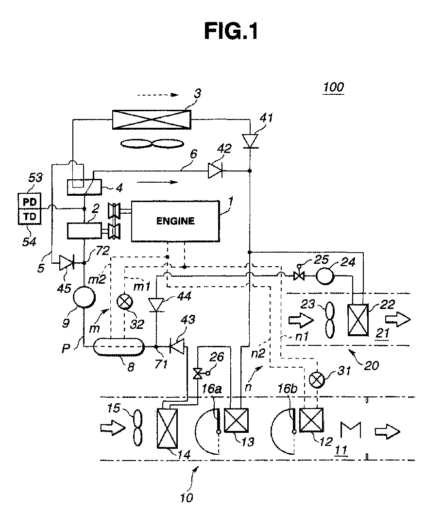
(57) An air conditioning system for a motor vehicle powered by an internal combustion
engine (1) has a first system for carrying out a first cycle, which includes a compressor
(2) driven by the engine (1), a main condenser (3), a first sub-condenser (13) and
an evaporator (14) which are connected through pipes to form a first refrigerant circulation
circuit through which a refrigerant flows from an outlet of the compressor (3) to
an inlet of the same while changing its phase, the first cycle causing the first sub-condenser
(13) as a heater and the evaporator (14) as a cooler when operated. The air conditioning
system has further a second system for carrying out a second cycle, which includes
the compressor (3) and a second sub-condenser (22) which are connected through pipes
to form a second refrigerant circulation circuit through which the refrigerant flows
from the outlet of the compressor (3) to the inlet of the same while changing its
phase, the second cycle causing the second sub-condenser (22) as a heater when operated.
First (11) and second (21) independent air flow passages are defined. The first passage
(11) has the heater core (12), the first sub-condenser (13) and the evaporator (14)
installed therein, and the second passage (21) has the second sub-condenser (22) installed
therein. A sub-evaporator (8) is arranged in the pipe extending from an outlet of
the second sub-condenser (22) to an inlet of the compressor (3). A cooling water circuit
is arranged through which engine cooling water of the engine (1) is fed to the sub-evaporator
(8) to carry out heat exchange between the engine cooling water and the refrigerant
flowing in the pipe. A control device is arranged to control, when the second system
is under operation, the flow of engine cooling water directed to the sub-evaporator
in accordance with a load of the engine.
|
|
