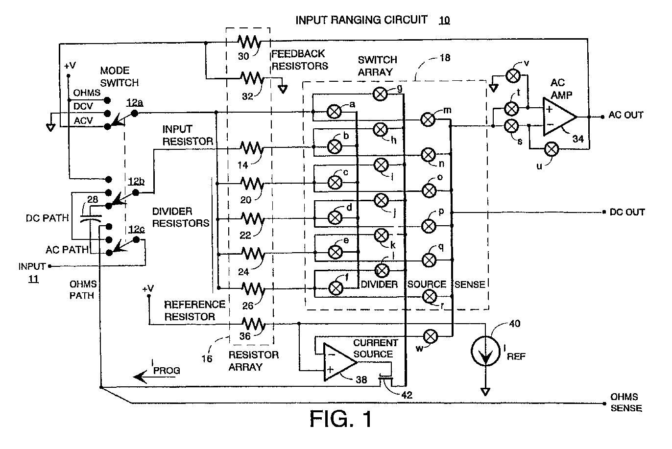
(57) An input ranging circuit for an electronic instrument that allows for measuring a.c.
voltage, d.c. voltage, and d.c. resistance is provided. The voltage ranging circuit
has three modes, d.c. volts, a.c. volts, and ohms, which are selected by a mode switch.
A resistor network containing an input resistor, feedback resistors, a reference resistor,
and divider resistors provides resistances that are ratiometrically scaled to maintain
relatively tight ratio tolerances. A switch array coupled to the resistor network
provides for the selected circuit configuration and divider ratio in conjunction with
the mode switch. Each of the switches in the switch array may be independently controlled
via control signals. In d.c. volts mode, the input voltage is divided down according
to a desired voltage divider ratio. In a.c. volts mode, the voltage divider is supplemented
with an a.c. amplifier configured to extend the useful bandwidth of the input ranging
circuit. In ohms mode, a programmable current scaled according to the ratio of resistances
in the resistor network is induced through an unknown resistance and the voltage drop
is provided at an ohms sense output.
|
|
