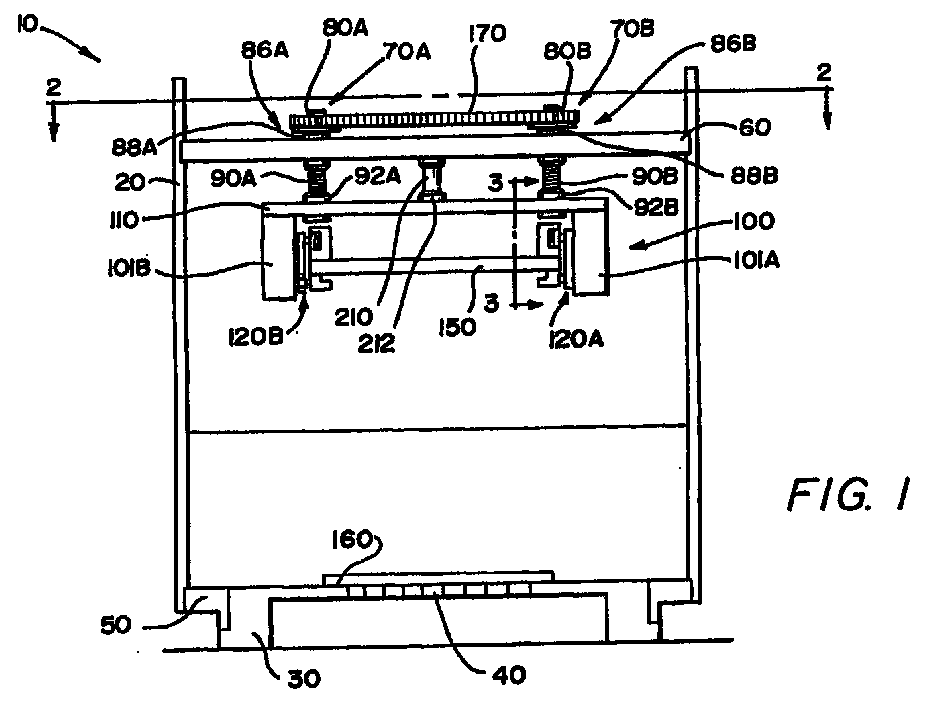
(57) A mechanical press (10) is provided incorporating a stationary frame (20) attached
to a probe card testing assembly (30). Four elongated rotatable lead screws (70A),
(70B), (70C), (70D) protrude through the press mount (60) of the stationary frame
(20) in order to moveably support a press assembly (100), thereby permitting height
adjustment. Each of the lead screws (70A), (70B), (70C), (70D) has a timing belt pulley
or similar means (80A), (80B), (80C), (80D) for synchronous power transmission disposed
above the press mount (60) for driving the lead screws (70A), (70B), (70C), (70D).
A timing belt or similar continuous belt or chain (170) engages each belt pulley (80A),
(80B), (80C), (80D), thereby synchronizing the rotation of the lead screws (70A),
(70B), (70C), (70D). The timing belt (170) is further engaged with the teeth of a
bi-directionally rotatable drive shaft (210) proximal the stationary frame (20). The
drive shaft (210) and, accordingly, the lead screws (70A), (70B), (70C), (70D) are
bi-directionally rotated in unison by an electrically-powered programmable motor (190)
thereby permitting the press assembly (100) to be moved upwards or downwards. The
press assembly (100), which is suspended by the lead screws (70A), (70B), (70C), (70D),
comprises a press assembly upper plate (110), side plates (101A), (101B) attached
to press assembly upper plate (110), a plate (150) attached to the side plates (101A),
(101B), and actuator mechanisms (120A), (120B) attached to the plate (150). The press
assembly (100) has a plurality of synchronized force-applying members (116A), (118A)
that, when actuated, cause the plate (150) to move rapidly downward a predetermined
distance. A shuttle system (220) comprising a drawer (230) and a pair of rails (240),
(241) may optionally be provided to allow automatic and convenient PCB insertion into
and removal from the testing assembly (30).
|
|
