| (19) |
 |
|
(11) |
EP 0 985 590 B1 |
| (12) |
EUROPEAN PATENT SPECIFICATION |
| (45) |
Mention of the grant of the patent: |
|
02.07.2003 Bulletin 2003/27 |
| (22) |
Date of filing: 02.09.1999 |
|
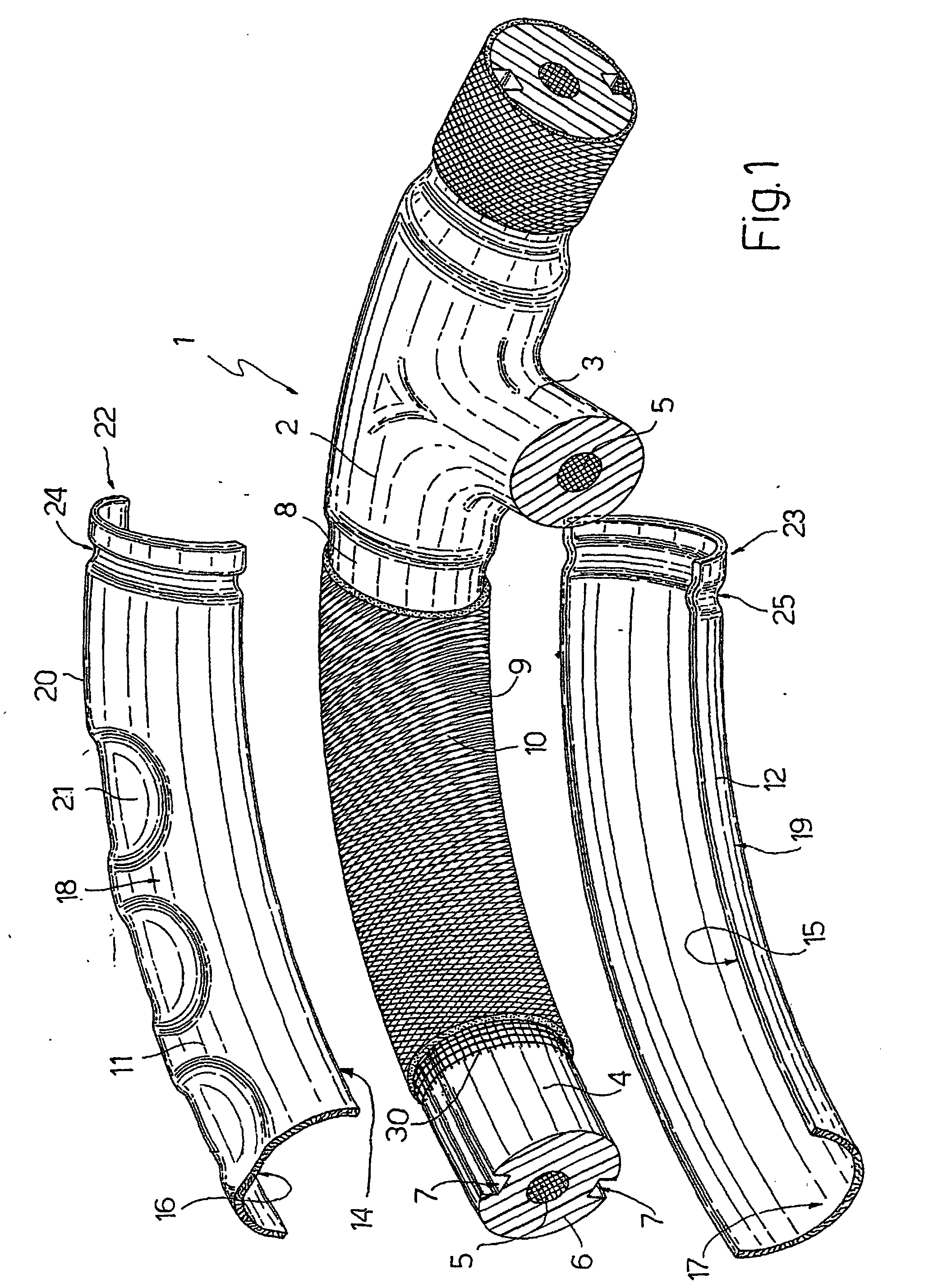
| (51) |
International Patent Classification (IPC)7: B62D 1/06 |
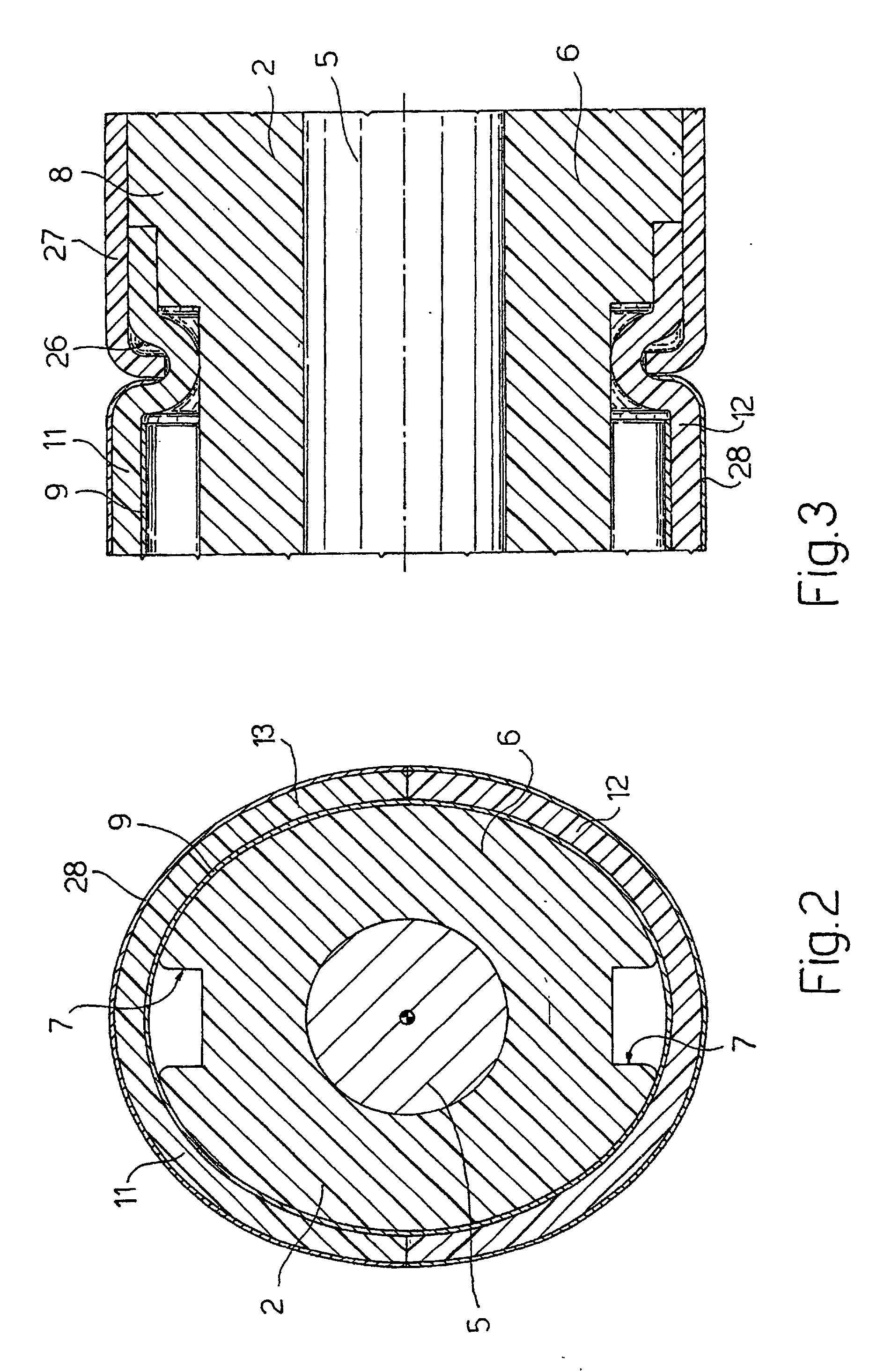
|
| (54) |
Method of producing vehicle steering wheels, in particular steering wheels with a
covering of valuable material; and steering wheels produced using such a method
Verfahren zum Herstellen von Kraftfahrzeuglenkrädern, insbesondere Lenkräder mit einer
Hülle aus hochwertigem Material, und durch ein solches Verfahren hergestellte Lenkräder
Procédé pour fabriquer des volants de direction de véhicule, en particulier des volants
avec un revêtement de matériaux de haute valeur, et des volants fabriqués avec un
tel procédé
|
| (84) |
Designated Contracting States: |
|
DE ES FR GB IT SE |
| (30) |
Priority: |
03.09.1998 IT TO980743
|
| (43) |
Date of publication of application: |
|
15.03.2000 Bulletin 2000/11 |
| (73) |
Proprietor: CAVALLI S.r.l. |
|
21040 Cislago (IT) |
|
| (72) |
Inventor: |
|
- Cavalli, Luigi
21047 Saronno (IT)
|
| (74) |
Representative: Franzolin, Luigi et al |
|
STUDIO TORTA S.r.l.,
Via Viotti, 9
10121 Torino
10121 Torino (IT) |
| (56) |
References cited: :
WO-A-97/43164
DE-C- 4 039 138
|
DE-A- 19 746 472
DE-U- 29 802 578
|
|
| |
|
|
|
|
| |
|
| Note: Within nine months from the publication of the mention of the grant of the European
patent, any person may give notice to the European Patent Office of opposition to
the European patent
granted. Notice of opposition shall be filed in a written reasoned statement. It shall
not be deemed to
have been filed until the opposition fee has been paid. (Art. 99(1) European Patent
Convention).
|
[0001] The present invention relates to a new method of producing vehicle steering wheels,
and which is particularly suitable for producing steering wheels with a covering of
valuable material, e.g. brier; and to steering wheels produced using such a method.
[0002] In the automotive industry, various types of wooden steering wheels are produced
using various methods. One of these consists in producing rings of shaped laminated
wood, possibly with a brier veneer, which are fitted to a supporting structure of
the steering wheel. Though relatively cheap to make, steering wheels produced this
way are unsatisfactory in appearance and normally cannot be made from the same type
of wood used for other interior parts of the vehicle (e.g. door panels, dashboard,
etc.). Another known method consists in veneering a polymer (typically polyurethane)
layer of the steering wheel structure with one or more layers of brier. While providing
for a fairly attractive appearance, this method is relatively expensive and, from
the manufacturing standpoint, involves serious problems as regards adhesion of the
wood veneer to the underlying polymer support, on account of the different chemical
and physical properties of the two materials.
[0003] The same drawbacks in terms of cost or poor appearance also apply to other known
methods of producing wooden or wood-veneered steering wheels.
[0004] A method of producing a steering wheel and a steering wheel according to the preamble
of claim 1 and claim 11 respectively are known from WO-A-97 43 164.
[0005] It is therefore an object of the present invention to provide a method of producing
vehicle steering wheels, which, unlike the above known methods, provides for achieving
a highly attractive appearance, in particular matching the other interior parts of
the vehicle, and which at the same time is straightforward and cheap to implement.
[0006] According to the present invention, there is provided a method of producing vehicle
steering wheels, in particular steering wheels with a covering of valuable material;
characterized by comprising the steps of:
- forming a supporting structure of a steering wheel, the structure having at least
one outer cover layer of a polymer material of predetermined density;
- forming at least one pair of curved preformed half-shells shaped and sized to fit,
facing each other, on opposite sides about a predetermined portion of said structure,
so as to define a substantially continuous, tubular shell covering said structure
portion;
- winding at least one layer of cloth, impregnated with a polymer resin, about said
structure portion and over said outer cover layer of the structure;
- applying said at least one pair of preformed half-shells to said at least one layer
of impregnated cloth to form said substantially continuous, tubular shell covering
said structure portion;
- producing a polymerization reaction of said polymer resin to bond said preformed half-shells
to each other and, via the interposition of said at least one layer of cloth, to said
outer cover layer of said structure.
[0007] Said step of forming said supporting structure of said steering wheel preferably
in turn comprises a step of forming in said outer cover layer of said structure at
least one recessed portion permitting thermal expansion of said polymer material.
[0008] The present invention also relates to a vehicle steering wheel comprising a supporting
structure of said steering wheel, the structure having at least one outer cover layer
of a polymer material of predetermined density; and characterized by also comprising
at least one pair of curved preformed half-shells fitted, facing each other, on opposite
sides about at least one corresponding predetermined portion of said structure, or
about the whole of the structure, so as to define a substantially continuous, tubular
shell covering said structure portion; at least one layer of cloth, impregnated with
a polymer resin, being wound about said structure portion, over said outer cover layer
of the structure, and being interposed radially between said outer cover layer of
said structure and said preformed half-shells.
[0009] Said supporting structure of said steering wheel preferably comprises, in said outer
cover layer of polymer material, at least one recessed portion permitting thermal
expansion of said polymer material.
[0010] The present invention therefore provides for producing, at relatively low cost, highly
functional vehicle steering wheels with a covering of valuable material, e.g. real
wood, and in particular of the same type of wood used for other interior parts of
the vehicle (door panels, dashboard, etc.) to achieve a highly attractive effect.
[0011] The layer of impregnated cloth interposed between the polymer (e.g. polyurethane)
supporting structure and the preformed half-shells (e.g. made of multilayer material
with a sandwich structure of wood and cloth impregnated with polymer resin) ensures
strong adhesion of the half-shells to each other and to the structure, despite the
chemical incompatibility and poor natural adhesion of wood and polyurethane (or similar
polymers). Moreover, the recessed portion in the outer cover layer of the structure
permits thermal expansion of the polymer material of the. outer cover layer without
radially compressing the preformed half-shells fitted to the outer cover layer, thus
preventing thermal expansion of the structure from deforming, warping or even detaching
the half-shells.
[0012] Moreover, beneath or together with the layer of impregnated cloth, the steering wheel
structure may be wound with an electric resistance heating element, which, being substantially
incorporated in the cloth layer, does not raise the overlying layers. The present
invention therefore provides for producing, in a straightforward, low-cost manner,
heated steering wheels with a wood veneer or covering of other valuable material,
and of flawless finish.
[0013] A non-limiting embodiment of the invention will be described by way of example with
reference to the accompanying drawings, in which:
Figure 1 shows a partial schematic view of a steering wheel in accordance with the
invention, in the course of manufacture;
Figure 2 shows a cross section of the Figure 1 steering wheel as assembled;
Figure 3 shows a longitudinal section of a detail of the Figure 1 steering wheel as
assembled.
[0014] With reference to Figures 1 to 3, number 1 indicates as a whole a vehicle steering
wheel, in particular for a car. Steering wheel 1 comprises a supporting structure
2 of any shape and having at least one spoke 3 connected integrally to the vehicle
steering column (not shown). For the sake of simplicity, reference is made in the
following description to only one portion 4 of structure 2, located at spoke 3 and
as shown in detail in Figure 1. It is understood, however, that the following description
also applies to any of a number of portions into which structure 2 may be divided,
as well as to the whole of steering wheel 1.
[0015] Structure 2 in turn comprises a metal core 5 enclosed in an outer cover layer 6 of
a polymer material of predetermined density, e.g. low-expansion polyurethane.
[0016] According to the invention, outer cover layer 6 of structure 2 comprises at least
one recessed portion 7 to permit thermal expansion of the polymer material from which
outer cover layer 6 is made : in the example shown, two diametrically-opposite circumferential
grooves 7 are formed in outer cover layer 6 and extend along the whole length of portion
4 of structure 2 up to a connecting portion 8 for connection to spoke 3.
[0017] At least one layer 9 of cloth 10 impregnated with a polymer resin is wound about
portion 4 of structure 2, over outer cover layer 6 of the structure : advantageously,
though not necessarily, a commercial glass or polyester gauze impregnated, for example,
with epoxy or melamine resin may be used. Over layer 9 of impregnated cloth 10, two
curved preformed half-shells 11, 12 are fitted, facing each other, on opposite sides
about portion 4 of structure 2 to define a substantially continuous, tubular shell
13 covering portion 4 of structure 2, so that layer 9 of impregnated cloth 10 is interposed
radially between outer cover layer 6 of structure 2 and preformed half-shells 11,
12. Half-shells 11, 12 form two symmetrical halves of tubular shell 13, which are
separated longitudinally and connected along respective end edges 14, 15 of half-shells
11, 12 to define continuous tubular shell 13, which is arc-shaped in the example shown,
and houses structure 2, in particular portion 4 of structure 2, of steering wheel
1. Respective inner lateral surfaces 16, 17 of half-shells 11, 12 are substantially
smooth and even, while respective outer lateral surfaces 18, 19 of half-shells 11,
12 may be of any shape, in particular to improve grip of steering wheel 1, and comprise,
for example, a succession of ridges 20 and impressions 21 (shown schematically on
half-shell 11 in Figure 1).
[0018] Preformed half-shells 11, 12 may be made of known multilayer composite material with
a sandwich structure, in particular comprising an inner layer of wood, at least one
intermediate layer of cloth impregnated with polymer adhesive, and an outer surface
layer - of wood or not - defined for example by a brier veneer or made of kevlar,
aluminium or other valuable material.
[0019] In the preferred embodiment shown, preformed half-shells 11, 12 comprise, at respective
longitudinal ends 22, 23 adjacent to connecting portion 8 for connection to spoke
3, respective transverse seats 24, 25, which, when half-shells 11, 12 are connected
to form tubular shell 13, define a continuous annular seat 26 in which to clinch a
surface covering 27, e.g. of leather, applied visibly to structure 2 on the opposite
side, circumferentially, to half-shells 11, 12, e.g. to cover connecting portion 8
for connection to spoke 3.
[0020] Half-shells 11, 12 may, of course, be shaped to comprise portions or cheeks (not
shown) extending over all or part of spoke 3 (or all the spokes of steering wheel
1); in which case, clinching seats for surface covering 27, equivalent to seats 24,
25 described above, may be formed on the cheeks of half-shells 11, 12 covering spoke
3, and may, for example, extend crosswise to spoke 3, i.e. circumferentially with
respect to steering wheel 1. Half-shells 11, 12 may also, of course, be of any circumferential
extension, even to the point of covering the whole circumference of steering wheel
1; and the outer lateral surfaces of half-shells 11, 12 may obviously be finished
in any known manner, in particular, by applying a coat of paint 28.
[0021] According to a further aspect of the invention, steering wheel 1 may also comprise
a known marketed electric resistance heating element 30 (shown schematically only
in Figure 1 for the sake of simplicity) made, for example, of mesh, cloth or sponge
with built-in electric resistors connectable to an external source, and which is wound
about outer cover layer 6 of structure 2, beneath or incorporated in layer 9 of impregnated
cloth 10. The electric resistors may, of course be simply incorporated in cloth 10
of layer 9.
[0022] According to the present invention, steering wheel 1 as described above is formed
as follows. To begin with, supporting structure 2 of steering wheel 1, comprising
metal core 5 and outer cover layer 6 of polymer material, is formed in substantially
known manner; and the two diametrically-opposite circumferential grooves 7 described
above, or other equivalent recessed portions permitting thermal expansion of the polymer
material of outer cover layer 6, are formed in known manner in outer cover layer 6.
[0023] Apart, curved preformed half-shells 11, 12 for covering each portion 4 into which
structure 2 is divided are formed of appropriate shape and size, for example, from
sheets of multilayer sandwich composite material comprising an inner layer of wood
and an outer surface layer of valuable material (e.g. brier, carbon fiber, etc.) bonded
to each other via the interposition of one or more layers of cloth impregnated with
polymer adhesives, e.g. epoxy or, better still, melamine resins. The sheets are placed
inside specially shaped molds for molding into the shape of half-shells 11, 12.
[0024] Purely by way of a non-limiting example, half-shells 11, 12 are prepared as follows.
For each half-shell to be produced, a corresponding multilayer package is prepared
comprising: an inner sheet of wood (tulipiè) which is eventually placed contacting
layer 9 of impregnated cloth 10; a sheet of gauze (commercial woven glass or polyester
fiber gauze) preimpregnated with melamine resin; a further sheet of wood (tulipiè);
a further two sheets of preimpregnated gauze; and a final layer of brier, to a total
thickness of about 2 mm. As compared with other resins (particularly accelerated epoxy
resins), materials preimpregnated with melamine resin have the advantage of being
storable at ambient temperature with no particular precautions required : once impregnated
with liquid melamine resin, the sheets of gauze (or other cloth) are oven-dried to
remove the solvents with which the resin is normally sold, but without initiating
the polymerization reaction, so that the resulting preimpregnated material is ready
for use to form the packages, described above, from which to form half-shells 11,
12. Moreover, materials preimpregnated with melamine resin require no catalysts or
accelerators for the polymerization reaction, which takes place entirely when forming
half-shells 11, 12.
[0025] Purely by way of a non-limiting example, the process parameters for molding half-shells
11, 12 may be as follows:
- average mold temperature: 120-180°C (polymerization temperature: about 130°C)
- pressing time: 100-350 seconds
- mold closing pressure: 30-100 bar
[0026] Once formed, half-shells 11, 12 may obviously be cut, milled or otherwise worked
in any known manner.
[0027] By means, for example, of a substantially known bandaging machine, structure 2 is
wound, over outer cover layer 6, with at least one layer 9 of cloth 10 (preferably
glass or polyester gauze) impregnated with polymer (preferably epoxy) resin and designed,
according to the invention, to ensure adhesion of half-shells 11, 12 to each other
and to the underlying outer cover layer 6. Layer 9 of cloth 10 may be preimpregnated
with polymer resin before being wound onto outer cover layer 6, or may be impregnated
with polymer resin after being wound onto outer cover layer 6, but obviously prior
to application of preformed half-shells 11, 12. Whichever the case, preformed half-shells
11, 12 are then applied on layer 9 of impregnated cloth 10 to form substantially continuous,
tubular shell 13 covering portion 4 or structure 2. Finally, a polymerization reaction
is produced of the polymer resin with which cloth 10 is impregnated, to bond half-shells
11, 12 to each other and, via the interposition of layer 9 of cloth 10, to outer cover
layer 6 of structure 2.
[0028] The step to produce the polymerization reaction of the polymer resin with which layer
9 of cloth 10 is impregnated, and to bond half-shells 11, 12 to each other and to
structure 2, is performed in a heated, e.g. aluminium, mold into which structure 2,
complete with preformed half-shells 11, 12, is inserted; and the mold is brought to
and maintained for a predetermined time at a sufficient temperature to produce the
polymerization reaction of the polymer resin with which cloth 10 is impregnated. As
will be obvious to an expert in the field, the operating conditions at this step depend
on the type of polymer resin used. For example, using glass gauze impregnated with
Corepox 2007 epoxy resin marketed by ALCA Resine S.r.l., the process parameters may
be as follows:
- type of resin: Corepox 2007 (epoxy)
- resin/hardener weight ratio: 10:1 to 10:6
- quantity of resin applied: 10 to 60 g/cm2
- polymerization temperature: 100-180°C
- polymerization time: 3-15 minutes
- mold closing pressure: 3-10 bar
[0029] At this step, the polymer resin with which cloth 10 is impregnated adheres to inner
lateral surfaces 16, 17 and penetrates between end edges 14, 15 of half-shells 11,
12 to substantially form an end-to-end bond. Alternatively, adhesive may obviously
be applied directly to end edges 14, 15 of half-shells 11, 12 to bond the end edges
together.
[0030] The mold is appropriately shaped to impart a predetermined shape to one of or both
half-shells 11, 12: in particular, the succession of ridges 20 and impressions 21.
Circumferential grooves 7 enable the polymer material of outer cover layer 6 to expand
without exerting radial pressure on, and so deforming, half-shells 11, 12; and any
further in-service expansion of the polymer material of outer cover layer 6 is also
taken up by circumferential grooves 7 to safeguard the uniformity and adhesion of
half-shells 11, 12.
[0031] As already stated, half-shells 11, 12 may advantageously, though not exclusively,
be made of multilayer material with a sandwich structure comprising an outer surface
layer of valuable material. Alternatively, half-shells 11, 12 may be made of multilayer
composite material of the type described previously, but without the outer surface
layer of valuable material; in which case, respective outer surface layers of valuable
material, e.g. brier veneer or kevlar, are applied to preformed half-shells 11, 12
after the half-shells are formed apart, e.g. when preformed half-shells 11, 12 have
already been applied to layer 9 of impregnated cloth 10.
[0032] Obviously, the method described may be followed by standard operations to surface
finish tubular shell 13 defined by half-shells 11, 12; which operations may comprise,
for example, polishing and varnishing, as well as application of cover 27, e.g. of
leather, between tubular shell 13 and connecting portion 8 for connection to spoke
3; which application, as stated, is made possible by continuous annular clinching
seat 26.
[0033] If provided, heating element 30 is obviously wound onto portion 4 of structure 2,
over outer cover layer 6, prior to applying preformed half-shells 11, 12, and prior
to or simultaneously with application of layer 9 of cloth 10, so that heating element
30 is either covered by or incorporated in layer 9.
1. A method of producing vehicle steering wheels (1), in particular steering wheels with
a covering of valuable material; comprising the steps of:
- forming a supporting structure (2) of a steering wheel (1), the structure having
at least one outer cover layer (6) of a polymer material of predetermined density;
- forming at least one pair of curved preformed half-shells shaped (11, 12) and sized
to fit, facing each other, on opposite sides about a predetermined portion (4) of
said structure, so as to define a substantially continuous, tubular shell (13) covering
said structure portion (4); characterized by further comprising the steps of
- winding at least one layer (9) of cloth (10), impregnated with a polymer resin,
about said structure portion (4) and over said outer cover layer (6) of the structure
(2);
- applying said at least one pair of preformed half-shells (11, 12) to said at least
one layer (9) of impregnated clothe (10) to form said substantially continuous, tubular
shell (13) covering said structure portion (4);
- producing a polymerization reaction of said polymer resin to bond said preformed
half-shells (11, 12) to each other and, via the interposition of said at least one
layer (9) of cloth (10), to said outer cover layer (6) of said structure (2).
2. A method as claimed in Claim 1, characterized in that said step of forming said supporting structure (2) of said steering wheel (1) in
turn comprises a step of forming in said outer cover layer (6) of said structure (2)
at least one recessed portion permitting thermal expansion of said polymer material.
3. A method as claimed in Claim 2, characterized in that said step of producing said polymerization reaction of said polymer resin is performed
in a heated mold, into which said structure (2), complete with said at least one pair
of preformed half-shells (11, 12), is inserted; said mold being so shaped as to impart
a predetermined final shape to said preformed half-shells (11, 12).
4. A method as claimed in Claim 2 or 3, characterized in that, in the course of said step of forming said supporting structure (2) of said steering
wheel (1), two diametrically-opposite, circumferential grooves (7) are formed in said
outer cover layer (6) of said structure (2), and which extend longitudinally along
substantially the whole extension of said structure portion (4).
5. A method as claimed in one of Claims 1 to 4, characterized in that said preformed half-shells (11, 12) are made from multilayer composite material comprising
an inner layer of wood, at least one intermediate layer of cloth impregnated with
a polymer adhesive, and an outer surface layer of valuable material, defined, for
example, by a brier veneer or by a layer of kevlar or aluminium.
6. A method as claimed in one of Claims 1 to 4,
characterized by comprising, after said step of applying said preformed half-shells (11, 12) to said
at least one layer (9) of impregnated cloth (10), a step of:
- applying to said preformed half-shells (11, 12) respective outer surface layers
of valuable material, defined, for example, by brier veneers or made of kevlar or
aluminium.
7. A method as claimed in one of the foregoing Claims, characterized in that said at least one layer (9) of cloth (10), preferably made of glass or polyester
gauze, is preimpregnated with said polymer resin before being wound onto said outer
cover layer (6) of said structure (2), or is impregnated with said polymer resin after
being wound onto said outer cover layer (6), but, at any rate, prior to application
of said preformed half-shells (11, 12); said polymer resin with which said at least
one layer (9) of cloth (10) is impregnated being selected from the group comprising
epoxy resins and melamine resins.
8. A method as claimed in one of the foregoing Claims, characterized in that said preformed half-shells (11, 12) comprise, at respective longitudinal ends, transverse
seats (24, 25) for clinching a surface covering (27), for example, a leather covering,
applied visibly to said structure.
9. A method as claimed in any one of the foregoing Claims,
characterized by also comprising, prior to said step of applying said preformed half-shells (11, 12)
to said at least one layer (9) of impregnated cloth (10), a step of:
- winding an electric resistance heating element (30) onto said structure portion
(4), over said outer cover layer (6) of the structure (2).
10. A method as claimed in the foregoing Claim, characterized in that said heating element (30) is made of mesh, cloth or sponge having built-in electric
resistors, and is wound onto said outer cover layer (6) of said structure portion
(4) prior to said at least one layer (9) of impregnated cloth (10) or simultaneously
with said at least one layer (9) of impregnated cloth (10), so that said heating element
(30) is covered by said at least one layer (9) of impregnated cloth (10) or is incorporated
in said at least one layer (9) of impregnated cloth (10).
11. A vehicle steering wheel (1) comprising a supporting structure (2) of said steering
wheel (1), the structure having at least one outer cover layer (6) of a polymer material
of predetermined density; at least one pair of curved preformed half-shells fitted
(11, 12), facing each other, on opposite sides about at least one corresponding predetermined
portion (4) of said structure (2), so as to define a substantially continuous, tubular
shell (13) covering said structure portion; and characterized by also comprising at least one layer (9) of cloth (10), impregnated with a polymer
resin, being wound about said structure portion (4), over said outer cover layer (6),
of the structure (2), and being interposed radially between said outer cover layer
(6) of said structure (2) and said preformed half-shells (11, 12).
12. A steering wheel as claimed in the foregoing Claim, characterized in that said supporting structure of said steering wheel comprises, in said outer cover layer
(6) of polymer material, at least one recessed portion permitting thermal expansion
of said polymer material.
13. A steering wheel as claimed in the foregoing Claim, characterized in that said supporting structure (2) of said steering wheel (1) comprises, in said outer
cover layer (6) of polymer material, two diametrically-opposite, circumferential grooves
(7) extending longitudinally along substantially the whole extension of said structure
portion (4).
14. A steering wheel as claimed in one of Claims 11 to 13, characterized in that said preformed half-shells (11, 12) are made from multilayer composite material comprising
an inner layer of wood, at least one intermediate layer of cloth impregnated with
a polymer adhesive, and an outer surface layer of valuable material, defined, for
example, by a brier veneer or by a layer of kevlar or aluminium.
15. A steering wheel as claimed in one of Claims 11 to 13, characterized by comprising, over said preformed half-shells (11, 12), respective outer surface layers
of valuable material, defined, for example, by brier veneers or made of kevlar or
aluminium.
16. A steering wheel as claimed in one of Claims 11 to 15, characterized in that said supporting structure (2) of the steering wheel (1) comprises a metal core (5)
enclosed in said outer cover layer (6) of polymer material; said polymer material
being polyurethane; said at least one layer (9) of cloth (10) being made of glass
or polyester gauze; and said polymer resin with which said at least one layer (9)
of cloth (10) is impregnated being selected from the group comprising epoxy resins
and melamine resins.
17. A steering wheel as claimed in one of Claims 11 to 16, characterized in that said preformed half-shells (11, 12) comprise, at respective longitudinal ends, transverse
seats (24, 25) for clinching a surface covering (27), for example, a leather covering.
18. A steering wheel as claimed in the foregoing Claim, characterized in that said respective longitudinal ends (22, 23) of said preformed half-shells are located
at a connecting portion (8) connecting said structure portion to a spoke (3) of said
steering wheel (1); said respective transverse seats (24, 25), when said half-shells
(11, 12) are connected to form said tubular shell (13), defining a continuous annular
seat by which to clinch said surface covering (27), which is applied visibly to said
structure, on the opposite side, circumferentially, to said half-shells (11, 12) to
cover said connecting portion.
19. A steering wheel as claimed in one of Claims 11 to 18, characterized by also comprising an electric resistance heating element (30) wound onto said outer
cover layer (6) of said structure portion (2), beneath said at least one layer (9)
of impregnated cloth (10) or incorporated in said at least one layer (9) of impregnated
cloth (10).
20. A steering wheel as claimed in the foregoing Claim, characterized in that said heating element (30) is made of mesh, cloth or sponge having built-in electric
resistors; said heating element (30) being covered by said at least one layer (9)
of impregnated cloth (10) or incorporated in said at least one layer (9) of impregnated
cloth (10).
1. Verfahren zum Herstellen von Fahrzeuglenkrädern (1), insbesondere Lenkrädern mit einer
Umhüllung aus wertvollem Material; umfassend die Schritte:
- Ausbilden einer Stützstruktur (2) eines Lenkrads (1), wobei die Struktur zumindest
eine äußere Hüllenlage (6) aus Polymermaterial mit vorgegebener Dichte aufweist;
- Ausbilden zumindest eines Paares von gekrümmten vorgeformten Halbschalen (11, 12),
die geformt und bemessen sind, um, wenn sie einander zugewendet sind, auf gegenüberliegende
Seiten auf einen vorgegebenen Bereich (4) der Struktur zu passen, um so eine im wesentlichen
kontinuierliche röhrenförmige Schale (13) zu definieren, welche den Strukturbereich
(4) bedeckt; dadurch gekennzeichnet, dass es weiterhin die Schritte umfasst:
- Wickeln zumindest einer Lage (9) aus Stoff (10), der mit einem Polymerharz imprägniert
ist, um den Strukturbereich (4) und über die äußere Abdecklage (6) der Struktur (2);
- Aufbringen des zumindest einen Paars vorgeformter Halbschalen (11, 12) auf die zumindest
eine Lage (9) imprägnierten Stoffs (10), um eine im wesentlichen kontinuierliche röhrenförmige
Schale auszubilden; welche den Strukturbereich (4) bedeckt;
- Erzeugen einer Polymerisationsreaktion des Polymerharzes, um die vorgeformten Halbschalen
(11, 12) miteinander und, über die Einfügung der zumindest einen Lage (9) aus Stoff
(10), an die äußere Hüllenlage (6) der Struktur (2) zu binden.
2. Verfahren gemäß Anspruch 1, dadurch gekennzeichnet, dass der Schritt des Ausbildens der Stützstruktur (2) des Lenkrads (1) wiederum einen
Schritt des Ausbildens zumindest einen vertieften Bereichs in der äußeren Hüllenlage
(6) der Struktur (2) umfasst, was eine thermische Ausdehnung des Polymermaterials
gestattet.
3. Verfahren gemäß Anspruch 2, dadurch gekennzeichnet, dass der Schritt des Erzeugens der Polymerisationsreaktion des Polymerharzes in einer
beheizten Form durchgeführt wird, in welche die Struktur (2), komplett mit dem zumindest
einen Paar von vorgeformten Halbschalen (11, 12) eingesetzt wird, wobei die Form so
ausgebildet ist, dass sie den vorgeformten Halbschalen (11, 12) eine vorgegebene Endform
vermitteln kann.
4. Verfahren gemäß Anspruch 2 oder 3, dadurch gekennzeichnet, dass im Verlauf des Schritts des Ausbildens der Stützstruktur (2) des Lenkrads (1) zwei
diametral entgegengesetzte Umfangsrillen (7) in der äußeren Hüllenlage (6) der Struktur
(2) gebildet werden, die sich längs im wesentlichen der ganzen Ausdehnung des Strukturbereichs
(4) erstrecken.
5. Verfahren gemäß einem der Ansprüche 1 bis 4, dadurch gekennzeichnet, dass die vorgeformten Halbschalen (11, 12) aus Mehrlagen-Kompositmaterial hergestellt
sind, die eine innere Lage aus Holz, zumindest eine Zwischenlage aus mit einem Polymeradhäsiv
imprägnierten Stoff und eine äußere Oberflächenlage aus wertvollem Material umfassen,
das beispielsweise durch ein Bruyère-Furnier oder eine Lage aus Kevlar oder Aluminium
definiert ist.
6. Verfahren gemäß einem der Ansprüche 1 bis 4,
dadurch gekennzeichnet, dass es nach dem Schritt des Aufbringens der vorgeformten Halbschalen (11, 12) auf die zumindest
eine Lage (9) imprägnierten Stoffes (10) einen Schritt des:
- Aufbringens von jeweiligen äußeren Oberflächenlagen wertvollen Materials, das beispielsweise
durch Bruyère-Furnier definiert oder aus Kevlar oder Aluminium hergestellt ist, auf
die vorgeformten Halbschalen (11, 12) umfasst.
7. Verfahren gemäß einem der vorstehenden Ansprüche, dadurch gekennzeichnet, dass die zumindest eine Lage (9) aus Stoff (10), vorzugsweise aus Glas- oder Polymergaze
hergestellt, vor dem Aufwickeln auf die äußere Hüllenlage (6) der Struktur (2) mit
dem Polymerharz vorimprägniert wird oder nach dem Aufwickeln auf die äußere Hüllenlage
(6) mit dem Polymerharz imprägniert wird, jedoch jedenfalls vor dem Aufbringen der
vorgeformten Halbschalen (11, 12); wobei das Polymerharz, mit dem die zumindest eine
Lage (9) aus Stoff (10) imprägniert ist, ausgewählt ist aus der Gruppe, die Epoxyharze
und Melaminharze umfasst.
8. Verfahren gemäß einem der vorstehenden Ansprüche, dadurch gekennzeichnet, dass die vorgeformten Halbschalen (11, 12) an jeweiligen Längsenden querlaufende Aufnahmen
(24, 25) zum Aufstecken einer Oberflächenumhüllung (27), beispielsweise einer Lederumhüllung,
die sichtbar auf die Struktur appliziert ist.
9. Verfahren gemäß einem der vorstehenden Ansprüche,
dadurch gekennzeichnet, dass es ebenfalls, vor dem Schritt des Aufbringens der vorgeformten Halbschalen (11, 12)
auf die zumindest eine Lage (9) aus imprägniertem Stoff (10)
einen Schritt des:
- Aufwickeln eines elektrischen Widerstands-Heizelements (30) auf den Strukturbereich
(4) über die äußere Hüllenlage (6) der Struktur (2) umfasst.
10. Verfahren gemäß dem vorstehenden Anspruch, dadurch gekennzeichnet, dass das Heizelement (30) aus einem Geflecht, Stoff oder Schwamm mit eingebauten elektrischen
Widerständen hergestellt ist und auf die äußere Abdecklage (6) des Strukturbereichs
(4) vor der zumindest einen Lage (9) aus imprägniertem Stoff (10) oder gleichzeitig
mit der zumindest einen Lage (9) aus imprägniertem Stoff (10) aufgewickelt wird, so
dass das Heizelement (30) von der zumindest einen Lage (9) aus imprägniertem Stoff
(10) umhüllt ist oder in die zumindest eine Lage (9) aus imprägniertem Stoff (10)
eingearbeitet ist.
11. Fahrzeuglenkrad (1), umfassend eine Stützstruktur (2) des Lenkrads (1), wobei die
Struktur zumindest eine äußere Hüllenlage (6) eines Polymermaterials vorgegebener
Dichte aufweist; zumindest ein Paar von gekrümmten vorgeformten Halbschalen (11, 12),
die einander gegenüberstehend auf entgegengesetzten Seiten an zumindest einem entsprechenden
vorgegebenen Bereich (4) der Struktur (2) angebracht sind, um so eine im wesentlichen
kontinuierliche röhrenförmige Schale (13) zu definieren, die den Strukturbereich umhüllt,
und dadurch gekennzeichnet, dass es ebenfalls umfasst zumindest eine Lage (9) aus Stoff (10), der mit einem Polymerharz
imprägniert ist, um den Strukturbereich (4) über der äußeren Hüllenlage (6) der Struktur
(2) zu wickeln und radial zwischen der äußeren Hüllenlage (6) der Struktur (2) und
den vorgeformten Halbschalen (11, 12) eingesetzt ist.
12. Lenkrad gemäß dem vorstehenden Anspruch, dadurch gekennzeichnet, dass die Stützstruktur des Lenkrads in der äußeren Hüllenlage (6) aus Polymermaterial
zumindest einen vertieften Bereich umfasst, der eine thermische Ausdehnung des Polymermaterials
gestattet.
13. Lenkrad gemäß dem vorstehenden Anspruch, dadurch gekennzeichnet, dass die Stützstruktur (2) des Lenkrads (1) in der äußeren Hüllenlage (6) aus Polymermaterial
zwei diametral entgegengesetzte Umfangsrillen (7) umfasst, die sich längs im wesentlichen
der ganzen Ausdehnung des Strukturbereichs (4) erstrecken.
14. Lenkrad gemäß einem der Ansprüche 11 bis 13, dadurch gekennzeichnet, dass die vorgeformten Halbschalen (11, 12) aus einem Mehrlagenkompositmaterial hergestellt
sind und eine innere Lage aus Holz, zumindest eine Zwischenlage aus mit einem Polymeradhäsiv
imprägnierten Stoff und eine äußere Oberflächenlage aus wertvollem Material umfassen,
das beispielsweise durch ein Bruyère-Furnier oder durch eine Lage von Kevlar oder
Aluminium definiert ist.
15. Lenkrad gemäß einem der Ansprüche 11 bis 13, dadurch gekennzeichnet, dass es über den vorgeformten Halbschalen (11, 12) jeweils äußere Oberflächenlagen wertvollen
Materials umfasst, das beispielsweise durch Bruyère-Furnier definiert oder aus Kevlar
oder Aluminium hergestellt ist.
16. Lenkrad gemäß einem der Ansprüche 11 bis 15, dadurch gekennzeichnet, dass die Stützstruktur (2) des Lenkrads (1) einen Metallkern (5) umfasst, der in der äußeren
Hüllenlage (6) aus Polymermaterial eingeschlossen ist, wobei das Polymermaterial Polyurethan
ist; die zumindest eine Lage (9) aus Stoff aus Glasoder Polyestergaze hergestellt
ist und das Polymerharz, mit dem die zumindest eine Lage (9) ais Stoff (10) imprägniert
ist, aus der Gruppe ausgewählt ist, welche Epoxyharze und Melaminharze umfasst.
17. Lenkrad gemäß einem der Ansprüche 11 bis 16, dadurch gekennzeichnet, dass die vorgeformten Halbschalen (11, 12) an jeweiligen Längsenden querlaufende Aufnahmen
(24, 25) zum Aufstecken einer Oberflächenumhüllung (27) umfassen, beispielsweise einer
Lederumhüllung.
18. Lenkrad gemäß einem der vorstehenden Ansprüche, dadurch gekennzeichnet, dass die jeweiligen Längsenden (22, 23) der vorgeformten Halbschalen an einem Verbindungsbereich
(8) lokalisiert sind, der den Strukturbereich mit einer Speiche (3) des Lenkrads (1)
verbindet, wobei die jeweiligen querlaufenden Aufnahmen (24, 25), wenn die Halbschalen
(11, 12) zum Ausbilden der röhrenförmigen Schale (13) verbunden sind, eine kontinuierliche
ringförmige Aufnahme definieren, auf der die Oberflächenumhüllung (27), die sichtbar
an der Struktur auf der gegenüberliegenden Seite angebracht ist, umfänglich an den
Halbschalen (11, 12) aufgesteckt werden, um den Verbindungsbereich abzudecken.
19. Lenkrad gemäß einem der Ansprüche 11 bis 18, dadurch gekennzeichnet, dass es auch ein elektrisches Widerstands-Heizelement (30) umfasst, welches auf die äußere
Hüllenlage (6) des Strukturbereichs (2) unter der zumindest einen Lage (9) aus imprägniertem
Stoff (10) gewickelt oder in der zumindest einen Lage (9) aus imprägniertem Stoff
(10) eingearbeitet ist.
20. Lenkrad gemäß einem der vorstehenden Ansprüche, dadurch gekennzeichnet, dass das Heizelement (30) aus Maschengewebe, Stoff oder Schwamm mit eingebauten elektrischen
Widerständen hergestellt ist, wobei das Heizelement (30) von der zumindest einen Lage
(9) aus imprägniertem Stoff (10) abgedeckt oder in die zumindest eine Lage (9) aus
imprägniertem Stoff eingearbeitet ist.
1. Procédé de fabrication de volants de direction pour véhicule (1), tout particulièrement
des volants de direction dotés d'un revêtement en matériau précieux ;
caractérisé par le fait qu'il comprend les étapes suivantes :
former une structure de support (2) d'un volant de direction (1), la structure comprenant
au moins une couche de revêtement extérieur (6) d'un matériau polymère d'une densité
prédéterminée ;
former au moins une paire de préformées arquées demi gaines (11, 12) façonnées et
taillées pour s'adapter, en se faisant face, sur des côtés opposés de part et d'autre
d'une partie prédéterminée (4) de ladite structure, de manière à définir une gaine
tubulaire sensiblement continue (13) recouvrant ladite partie de structure (4), procédé
caractérisé par le fait qu'il comprend par ailleurs les étapes suivantes :
enrouler au moins une couche (9) de tissu (10) imprégné d'une résine polymère autour
de ladite partie de structure (4) et sur ladite couche de revêtement extérieur (6)
de la structure (2) ;
appliquer ladite au moins une paire de demi gaines préformées (11, 12) sur ladite
au moins une couche (9) de tissu imprégné (10), de manière à former ladite gaine tubulaire
sensiblement continue (13) recouvrant ladite partie de structure (4) ;
déclencher une réaction de polymérisation de ladite résine polymère de manière à assembler
lesdites demi gaines préformées (11, 12) l'une à l'autre et, par l'intermédiaire de
l'interposition de ladite au moins une couche (9) de tissu (10), sur ladite couche
de revêtement extérieur (6) de ladite structure (2).
2. Procédé selon la revendication 1, caractérisé en ce que ladite étape de formation de ladite structure de support (2) dudit volant de direction
(1) comprend à son tour une étape de formation à l'intérieur de ladite couche de revêtement
extérieur (6) de ladite structure (2) d'au moins une partie en retrait permettant
la dilatation thermique dudit matériau polymère.
3. Procédé selon la revendication 2, caractérisé en ce que ladite étape de déclenchement de ladite réaction de polymérisation de ladite résine
polymère est réalisée dans un moule chauffé, dans lequel est insérée ladite structure
(2), dotée de ladite paire au moins de demi gaines préformées (11, 12); ledit moule
ayant été usiné pour donner une forme finale prédéterminée aux dites demi gaines préformées
(11, 12).
4. Procédé selon la revendication 2 ou 3, caractérisé en ce que, pendant ladite étape de formation de ladite structure de support (2) dudit volant
de direction (1), deux rainures circonférentielles diamétralement opposées (7) sont
formées dans ladite couche de revêtement extérieur (6) de ladite structure (2) et
elles s'étirent de manière longitudinale sensiblement le long de toute l'extension
de ladite partie de structure (4).
5. Procédé selon l'une des revendications 1 à 4, caractérisé en ce que lesdites demi gaines préformées (11, 12) sont constituées d'un matériau composite
multicouche comprenant une couche intérieure en bois, au moins une couche intermédiaire
de tissu imprégné d'un adhésif polymérique, et une couche de surface extérieure en
matériau précieux, définie, par exemple, par un placage en bois de bruyère ou par
une couche de kevlar ou d'aluminium.
6. Procédé selon l'une des revendications 1 à 4,
caractérisé en ce qu'il comprend, après ladite étape d'application desdites demi gaines préformées (11,
12) sur ladite au moins une couche (9) de tissu imprégné (10), l'étape suivante :
appliquer sur lesdites demi gaines préformées (11, 12) des couches respectives de
surface extérieure en matériau précieux, définies, par exemple, par des placages en
bois ou constitués de kevlar ou d'aluminium.
7. Procédé selon l'une des revendications précédentes, caractérisé en ce que ladite au moins une couche (9) de tissu (10), constituée de préférence de gaze en
fibre de verre ou de polyester, est pré-imprégnée avec ladite résine polymère avant
d'être enroulée sur ladite couche de revêtement extérieur (6) de ladite structure
(2), ou est imprégnée de ladite résine polymère après avoir été enroulée sur ladite
couche de revêtement extérieur (6), mais, dans tous les cas, avant l'application desdites
demi gaines préformées (11, 12) ; ladite résine polymère avec laquelle ladite au moins
une couche (9) de tissu (10) est imprégnée, étant choisie dans le groupe comprenant
des résines époxy et de mélamine.
8. Procédé selon l'une des revendications précédentes, caractérisé en ce que lesdites demi gaines préformées (11, 12) comprennent, aux extrémités longitudinales
respectives, des logements transversaux (24, 25) destinés à assujettir un revêtement
de surface (27), par exemple un revêtement en cuir, appliqué de manière visible sur
ladite structure ;
9. procédé selon l'une quelconque des revendications précédentes,
caractérisé en ce qu'il comprend également, avant ladite étape d'application desdites demi gaines préformées
(11, 12) sur ladite au moins une couche (9) de tissu imprégné (10), l'étape suivante
:
enrouler un élément chauffant à résistance électrique (30) sur ladite partie de structure
(4), au-dessus de ladite couche de revêtement extérieur (6) de la structure (2).
10. Procédé selon la revendication précédente, caractérisé en ce que ledit élément chauffant (30) est constitué de mailles, d'un tissu ou d'une éponge
ayant des résistances électriques intégrées, et est enroulé sur ladite couche de revêtement
extérieur (6) de ladite partie de structure (4) avant ladite au moins une couche (9)
de tissu imprégné (10), ou simultanément avec ladite au moins une couche (9) de tissu
imprégné (10), de manière à ce que ledit élément chauffant (30) soit recouvert par
ladite au moins une couche (9) de tissu imprégné (10) ou qu'il soit incorporé dans
ladite au moins une couche (9) de tissu imprégné (10).
11. Volant de direction pour véhicule (1) comprenant une structure de support (20) dudit
volant de direction (1), la structure ayant au moins une couche de revêtement extérieur
(6) d'un matériau polymère d'une densité prédéterminée ; et caractérisé en ce qu'il comprend également au moins une paire de préformées arquées demi gaines (11, 12)
adaptées, en se faisant face, sur des côtés opposés de part et d'autre d'au moins
une partie prédéterminée correspondante (4) de ladite structure (2), de manière à
définir une gaine tubulaire sensiblement continue (13), recouvrant ladite partie de
structure, et caractérisé en ce qu'il comprend également au moins une couche (9) de tissu (10) imprégnée d'une résine
polymère, enroulée autour de ladite partie de structure (4), au-dessus de ladite couche
de revêtement extérieur (6) de ladite structure (2), et étant interposée radialement
entre ladite couche de revêtement extérieur (6) de ladite structure (2) et lesdites
demi gaines préformées (11, 12).
12. Volant de direction selon la revendication précédente, caractérisé en ce que ladite structure de support dudit volant de direction comprend, à l'intérieur de
ladite couche de revêtement extérieur (6) en matériau polymère, au moins une partie
en retrait permettant une dilatation thermique dudit matériau polymère.
13. Volant de direction selon la revendication précédente, caractérisé en ce que ladite structure de support (2) dudit volant de direction (1) comprend, à l'intérieur
de ladite couche de revêtement extérieur (6) en matériau polymère, deux rainures circonférentielles
diamétralement opposées (7), s'étirant de manière longitudinale sensiblement le long
de toute l'extension de ladite partie de structure (4).
14. Volant de direction selon l'une des revendications 11 à 13, caractérisé en ce que lesdites demi gaines préformées (11, 12) sont constituées d'un matériau composite
multicouche comprenant une couche intérieure en bois, au moins une couche intermédiaire
de tissu imprégné d'un adhésif polymérique, et une couche de surface extérieure en
matériau précieux, définie par exemple par un placage en bois de bruyère ou par une
couche de kevlar ou d'aluminium.
15. Volant de direction selon l'une des revendications 11 à 13, caractérisé en ce qu'il comprend, au-dessus desdites demi gaines préformées (11, 12), des couches respectives
de surface extérieure en matériau précieux, définies par exemple par des placages
en bois de bruyère ou constitués de kevlar ou d'aluminium.
16. Volant de direction selon l'une des revendications 11 à 15, caractérisé en ce que ladite structure de support (2) du volant de direction (1) comprend une âme métallique
(5) enfermée dans ladite couche de revêtement extérieur( 6) en matériau polymère ;
ledit matériau polymère étant du polyuréthane ; ladite au moins une couche (9) de
tissu (10) étant constituée d'une gaze en fibre de verre ou de polyester ; et ladite
résine polymère avec laquelle ladite au moins une couche (9) de tissu (10) est imprégnée
étant choisie dans le groupe comprenant des résines époxy et des résines mélamine.
17. Volant de direction selon l'une des revendications 11 à 16, caractérisé en ce que les demi gaines préformées (11, 12) comprennent, aux extrémités longitudinales respectives,
des logements transversaux (24, 25) destinés à fixer un revêtement de surface (27)
par exemple, un revêtement en cuir.
18. Volant de direction selon la revendication précédente, caractérisé en ce que lesdites extrémités longitudinales respectives (22, 23) desdites demi gaines préformées
sont situées au niveau d'une partie de raccordement (8) raccordant ladite partie de
structure à un bras (3) dudit volant de direction(1) ; lesdits logements transversaux
respectifs (24, 25), lorsque lesdites demi gaines (11, 12) sont raccordées de manière
à former ladite gaine tubulaire (13), définissant un logement annulaire continu permettant
d'assujettir ledit revêtement de surface (27), lequel est appliqué de manière visible
sur ladite structure, sur le côté opposé, de manière circonférentielle, sur lesdites
demi gaines (11, 12) de manière à recouvrir ladite partie de raccordement.
19. Volant de direction selon l'une des revendications 11 à 18, caractérisé en ce qu'il comprend également un élément chauffant à résistance électrique (30) enroulé sur
ladite couche de revêtement extérieur (6) de ladite partie de structure (2), au-dessous
de ladite au moins une couche (9) de tissu (10) imprégné, ou incorporé dans ladite
au moins une couche (9) de tissu imprégné (10).
20. Volant de direction selon la revendication précédente, caractérisé en ce que l'élément chauffant (30) est constitué de mailles, de tissu ou d'éponge ayant des
résistances électriques intégrées ; ledit élément chauffant (30) étant recouvert par
ladite au moins une couche (9) de tissu imprégné (10), ou incorporé dans ladite au
moins une couche (9) de tissu imprégné (10).