| (19) |
 |
|
(11) |
EP 1 006 280 B1 |
| (12) |
EUROPEAN PATENT SPECIFICATION |
| (45) |
Mention of the grant of the patent: |
|
17.08.2005 Bulletin 2005/33 |
| (22) |
Date of filing: 30.09.1999 |
|
|
| (54) |
Spherical gear pump
Kugelzahnradpumpe
Pompe à engrenages sphériques
|
| (84) |
Designated Contracting States: |
|
DE FR GB NL SE |
| (30) |
Priority: |
14.10.1998 ES 9802126
06.07.1999 ES 9901492
|
| (43) |
Date of publication of application: |
|
07.06.2000 Bulletin 2000/23 |
| (73) |
Proprietor: Munoz Saiz, Manuel |
|
04004 Almeria (ES) |
|
| (72) |
Inventor: |
|
- Munoz Saiz, Manuel
04004 Almeria (ES)
|
| (56) |
References cited: :
EP-A- 0 705 979
DE-A- 2 200 048
GB-A- 1 528 727
|
DE-A- 2 114 874
DE-A- 3 810 592
US-A- 3 817 666
|
|
| |
|
|
- PATENT ABSTRACTS OF JAPAN vol. 12, no. 57 (M-670), 20 February 1988 (1988-02-20) &
JP 62 203988 A (INOUE JAPAX RES INC.), 8 September 1987 (1987-09-08)
|
|
| |
|
| Note: Within nine months from the publication of the mention of the grant of the European
patent, any person may give notice to the European Patent Office of opposition to
the European patent
granted. Notice of opposition shall be filed in a written reasoned statement. It shall
not be deemed to
have been filed until the opposition fee has been paid. (Art. 99(1) European Patent
Convention).
|
BACKGROUND OF THE INVENTION
1. Field of the Invention:
[0001] Pumps, compressors, fluid motors and engines.
2. Description of The Related Art:
[0002] There are alternating or vane pumps, compressors, etc. which are complicated, and
of the turbine or fin type requiring high speeds to operate and of limited internal
hermetic seal.
[0003] Other like DE 22 00 048 uses two gears whose periphery or front zone is semicircular,
or DE 38 10 592 discloses an engine, formed three cylindrical pumps or JP 62203988
that discloses a Roots-type pump.
SUMMARY OF THE INVENTION
[0004] The drawbacks referred to above are eliminated with this invention that consists
of a spherical gear pump comprising two rotors or geared spheres, with the teeth arranged
around them in a circular band at right angles to their axis of rotation: the pump
spheres are covered by close-fitting spherical cases or housings except at the central
or most internal part of the connection between the gears on the two spheres. The
fluid contained in the cavity created between the most external gears and the case
is moved during rotation from the intake to the outlet.
[0005] The spherical gear pump operates similarly to a cylindrical pump. At least two teeth
per sphere can be used, though the most useful are those with 4-6 teeth. If 2 or 3
are used, the movement is transmited between the two spheres by means of additional
gears. The spheres and their coverings may be lightweight hard material and may also
be coated in a hard or hardened material. They may be hollow inside.
[0006] One sphere is driven by its shaft and the other is dragged by the gearing between
the two.
[0007] In the area of the spheres close to the shafts, or on the shafts themselves, there
may be some projections or washers which maintain a precision gauged distance between
the spheres and their cases or housings. Except for low speeds, bearings will be needed
on the ends of the spheres' rotary shafts.
[0008] The lubrication systems are similar to those of existing pumps, compressors, etc.
[0009] When the pump is used like compressor in internal combustion engines, said pump sends
the air to a combustion chamber where it is compressed and reacts with the fuel and
expands driving a low or mean speed turbine.
[0010] Benefits: good hermetic seal, particularly thanks to the spherical form of both the
rotors and the housings, so that expansion is more even: they are useful as vacuum
pumps. It is the best of the pumps and compressors (and motors, because it is reversible),
being simple and economical. Unlike fin compressors, high speeds are not required,
which is useful for addition as a compressor for gas turbines. Extremely small dimensions
are possible, and valves are not requiered. Few parts are employed, and there is no
alternating movement. Highly reliable, and good performance. The power/weight ratio
and power/volume ratios are similar to those of existing systems.
BRIEF DESCRIPTION OF THE DRAWINGS
[0011]
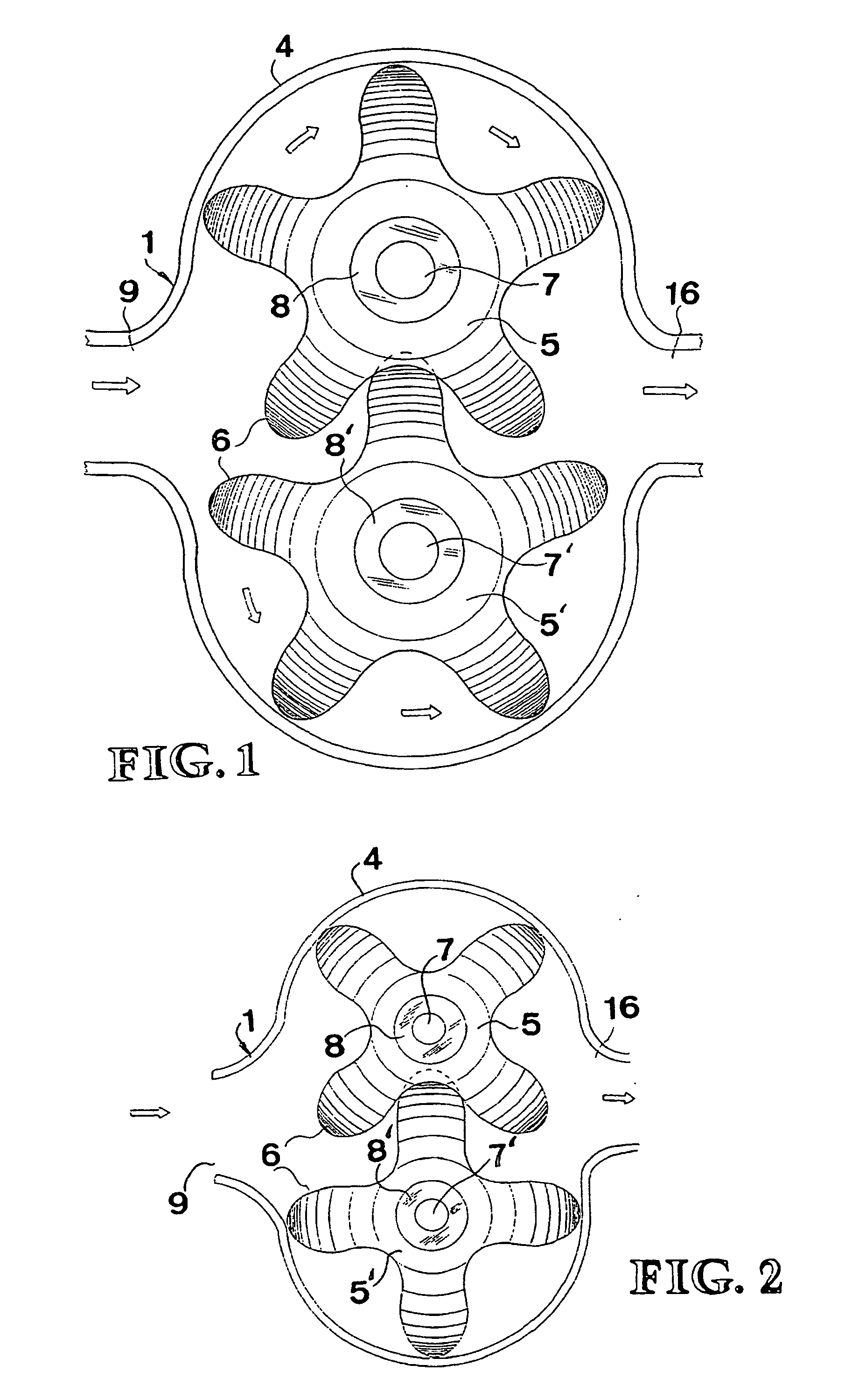
Figure 1 and 2 show side, schematic, partial, cross-section views of the pump, compressor,
motor, etc., of the invention.
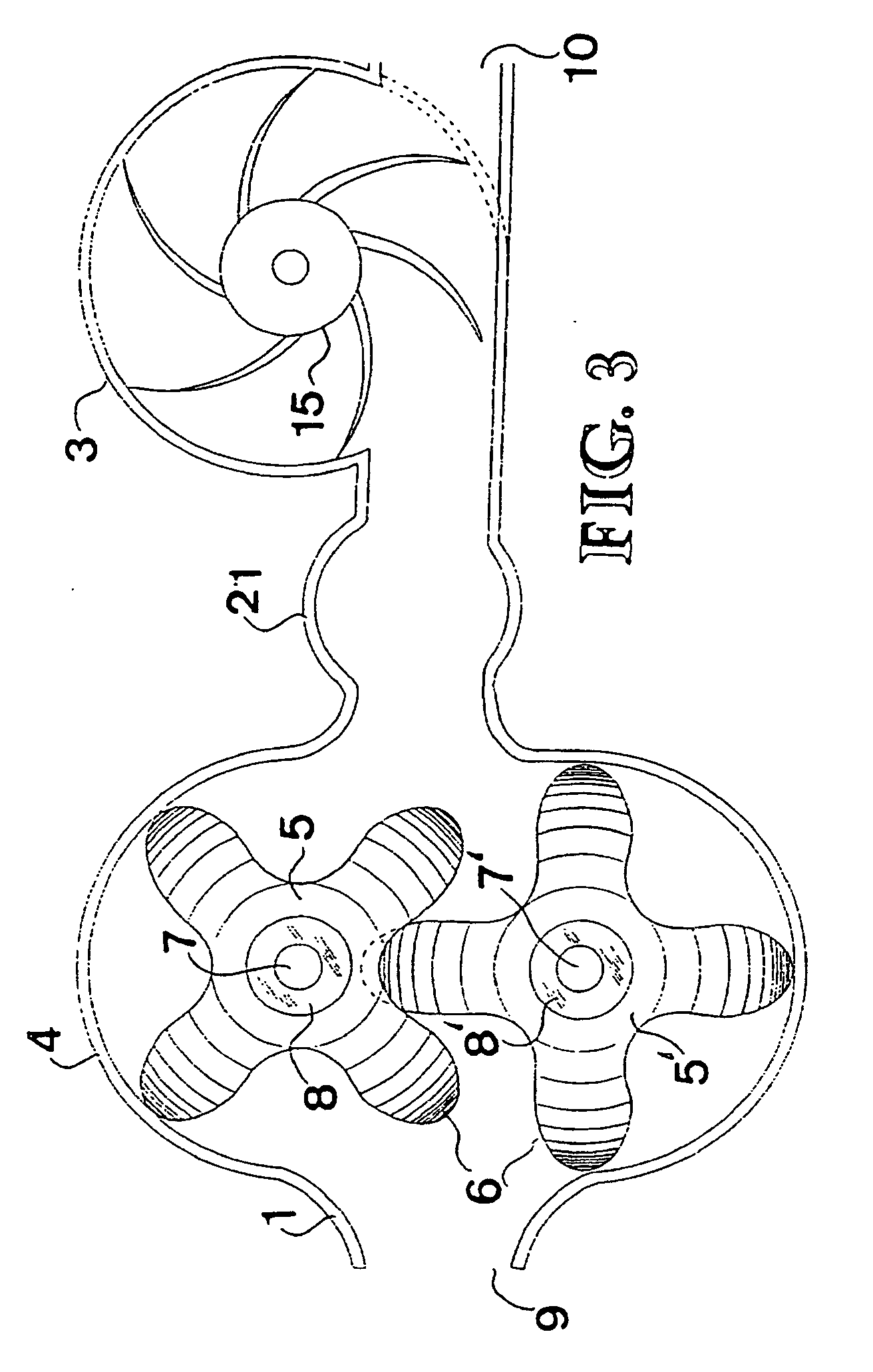
Figure 3 shows a side, schematic, partial, cross-section view of an engine with the
pump in the invention.
DETAILED DESCRIPTION OF THE PREFERRED EMBODIMENTS
[0012]
Figure 1 comprises the pump or compressor 1, case or housing 4, the rotors or geared
spheres 5 and 5' with 5 teeth, the rotary shafts 7 and 7', and the projection or washer
8 and 8' which mantain a precision gauged distance between the spheres and their housings.
When it rotates driving one of the shafts, the fluid contained ii the cavity created
between the most external gears and the cases or housings is moved during rotation
from the intake 9 to the outlet 16, as it is shown with arrows.
Figure 2 comprises the pump or compressor 1, the case or housing 2, the rotor or geared
spheres 5 and 5' with four teeht 6, the rotary shafts 7 and 7 and the projection or
washer 8 and 8' that creates a gap. It works in the same way as in figure 1.
Figure 3 comprises the pump or compressor 1, the combustion chamber 21 and the turbine
3, the pump case or housing 4, the rotors or geared spheres 5 and 5' with their teeht
6, the rotary shafts 7 and 7', the gap annular washers or springs 8 an 8', where 9
is the compressor or air intake, said compressor sends the air into the combustion
chamber where ir reacts with the fuel and expands driving the good hermetic seal radial
blades wheel, appling the gas fluid exhaust against the blades of a half of the turbine
3.
1. A gear pump of the two rotor type wherein the pump rotors (5,5') are covered by close
fitting cases or housings (4) except at the central or most internal part of the connection
between the gears on the two rotors, the fluid contained in the cavity created between
the most external gears and the case or housing being moved during rotation of the
rotors from an intake (9) to an outlet (16)
characterised in that
both rotors (5, 5') are constituted of two geared spheres with teeth arranged around
the geared spheres in a circular band at right angles to their axis of rotation (7,
7') and in that the cases or housings (4) of the rotors have a spherical shape.
2. A gear pump according to claim 1, wherein said spheres (5 and 5')and their coverings
(4)are lightweight hard material.
3. A gear pump according to claim 1, wherein said spheres (5 and5')cases are coated in
a hard or hardened material.
4. A gear pump according to claim 1, wherein said spheres (5and 5') are hollow inside.
5. A gear pump according to claim 1, wherein one sphere (5) is driven by a shaft and
the other is dragged by the gearing (6) between the two.
6. A gear pump according to claim 1, wherein in the area of the spheres (5 and 5') and
the shafts, or on the shafts themselves (7 and 7') there are some projections which
maintain a precision gauged distance between the spheres and their cases or housings.
7. A gear pump according to claim 1, wherein in the area of the spheres (5 and 5') and
the shafts, or on the shafts themselves (7 and 7') there are some washers (8 and 8')
which maintain a precision gauged distance between the sphere and their cases or housings
(4).
8. A gear pump according to claim 1, wherein each sphere has at least two teeth.
9. A gear pump according to claim 1, wherein the pump is used as a compressor (1) in
an internal combustion engine, said pump sends the air to a combustion chamber (21)
where it is compressed and reacts with the fuel and expands driving a low or mean
speed turbine (15).
1. Rotorpumpe mit zwei Rotoren, bei der die Rotoren der Pumpe (5, 5') durch Gehäuse oder
anliegende Verkleidungen (4) abgedeckt sind, mit Ausnahme des mittleren oder weiter
innenliegenden Verbindungsbereichs zwischen den Getrieben beider Rotoren, und das
in dem zwischen den weiter aussen liegenden Getrieben und dem Gehäuse bzw. der Verkleidung
gebildeten Hohlraum enthaltene Medium während der Rotation der Rotoren vom Eingang
(9) zum Ausgang (16) verlagert wird,
dadurch gekennzeichnet, dass die beiden Rotoren (5, 5') aus zwei gezahnten Kugeln bestehen, deren Zähne um die
Kugeln herum auf einem kreisförmigen Band im rechten Winkel zu den Drehachsen (7,
7') angeordnet sind und dass die Gehäuse oder Verkleidungen (4) der Rotoren die Form
einber Kugel haben.
2. Rotorpumpe nach Anspruch 1, dadurch gekennzeichnet, dass diese Kugeln (5 und 5') und ihre Gehäuse (4) aus einem leichten, harten Material
bestehen.
3. Rotorpumpe nach Anspruch 1, dadurch gekennzeichnet, dass diese Kugeln (5, 5') von einem harten oder gehärteten Material umgeben sind.
4. Rotorpumpe nach Anspruch 1, dadurch gekennzeichnet, dass diese Kugeln (5, 5') innen hohl sind.
5. Rotorpumpe nach Anspruch 1, dadurch gekennzeichnet, dass die eine Kugel (5) durch ihre Achse angetrieben und die andere durch den Eingriff
(6) der beiden Kugeln ineinander mitgenommen wird.
6. Rotorpumpe nach Anspruch 1, dadurch gekennzeichnet, dass in den Bereichen der Kugeln (5 und 5') und der Achsen oder der Achsen (7, 7') selbst
Vorsprünge vorhanden sind, die einen genau kalibrierten Abstand zwischen den Kugeln
und ihren Gehäusen halten.
7. Rotorpumpe nach Anspruch 1, dadurch gekennzeichnet, dass in den Bereichen der Kugeln (5 und 5') und der Achsen oder der Achsen (7, 7') selbst
Zwischenlegscheiben (8, 8') vorhanden sind, die einen genau kalibrierten Abstand zwischen
den Kugeln und ihren Gehäusen halten (4).
8. Rotorpumpe nach Anspruch 1, dadurch gekennzeichnet, dass jede Kugel über mindestens zwei Zähne verfügt.
9. Rotorpumpe nach Anspruch 1, dadurch gekennzeichnet, dass die Pumpe als Kompressor (1) einen Verbrennungsmotor einsetzt und dass die Pumpe
Luft in die Verbrennungskammer (21) pumpt, wo sie komprimiert wird, mit dem Brennstoff
eine Reaktion eingeht und sich dehnt, womit eine Turbine mit geringer oder mittlerer
Geschwindigkeit angetrieben wird (15).
1. Pompe à engrenages du type à deux rotors dans laquelle les deux rotors de la pompe
(5, 5') sont recouverts de carcasses ou de garnitures ajustées (4), sauf dans la zone
centrale ou plus interne de raccord entre les engrenages des deux rotors, le fluide
contenu dans la cavité créée entre les engrenages plus externes et la carcasse ou
garniture est déplacé pendant la rotation des rotors de l'entrée (9) à la sortie (16)
Caractérisée en ce que les deux rotors (5, 5') sont constitués de deux sphères dentées ayant les dents disposées
autour des sphères dentées sur une bande circulaire suivant des angles perpendiculaires
à leurs axes de rotation (7, 7') et en ce que les carcasses ou garnitures (4) des rotors ont une forme sphérique.
2. Pompe à engrenages conformément à la revendication 1, caractérisée en ce que ces sphères (5 et 5') et leurs carcasses (4) sont en matériau léger et dur.
3. Pompe à engrenages conformément à la revendication 1, caractérisée en ce que ces sphères (5 et 5') sont recouvertes d'un matériau dur ou durci.
4. Pompe à engrenages conformément à la revendication 1, caractérisée en ce que ces sphères (5 et 5') sont creuses à l'intérieur.
5. Pompe à engrenages conformément à la revendication 1, caractérisée en ce qu'une sphère (5) est impulsée au moyen de son axe et l'autre est entraînée par l'engrenage
(6) entre les deux sphères.
6. Pompe à engrenages conformément à la revendication 1, caractérisée en ce que dans les zones des sphères (5 et 5') et des axes, ou de ces mêmes axes (7, 7'), il
existe des parties saillantes qui maintiennent une distance calibrée et de précision
entre les sphères et leurs carcasses.
7. Pompe à engrenages conformément à la revendication 1, caractérisée en ce que dans les zones des sphères (5 et 5') et des axes, ou de ces mêmes axes (7, 7'), il
existe des rondelles (8, 8') qui maintiennent une distance calibrée et de précision
entre les sphères et leurs carcasses (4).
8. Pompe à engrenages conformément à la revendication 1, caractérisée en ce que chaque sphère dispose au moins de deux dents.
9. Pompe à engrenages conformément à la revendication 1, caractérisée en ce que la pompe est utilisée comme compresseur (1) dans un moteur à combustion interne,
cette pompe envoyant de l'air à la chambre de combustion (21) où il se comprime, réagit
avec le combustible et se dilate en impulsant une turbine à petite ou moyenne vitesse.
(15).