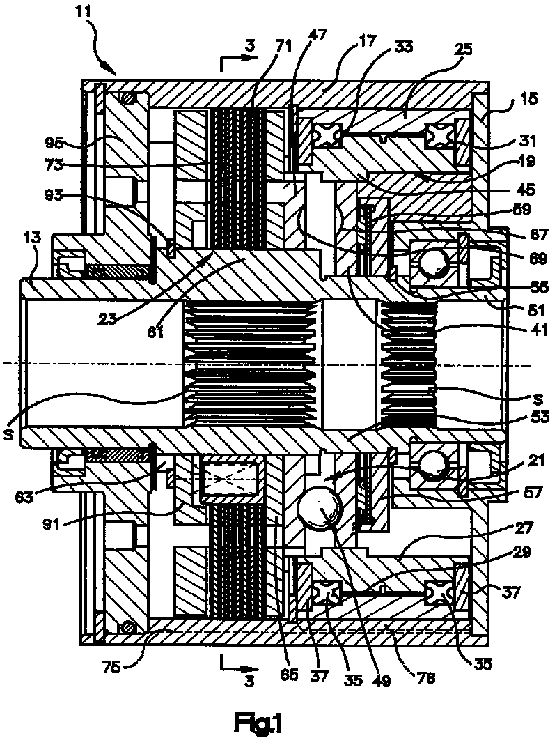
(57) A differential device (11) of the type including a clutch pack (23), engaged by a
ball ramp actuator (21), which is initiated by a viscous coupling (19;101). The output
of the device (11) is an output shaft (13) which is hollow and extends through the
entire axial extent of the device. The viscous coupling (19;101) includes, in the
embodiment of FIG. 1, an annular input coupling member (25) and an annular output
coupling member (27), within the input member, to define therebetween a cylindrical
viscous shear chamber (29). The output coupling member (27) at least partially surrounds
the first ramp plate (41) of the ball ramp actuator (21), and is in driving engagement
therewith, for improved packaging. The clutch pack (23) and the actuator (21) are
disposed about the output shaft (13) and axially retained between snap rings (55,93),
so that all axial separation forces generated within the clutch pack and the actuator
are taken up within a single member, such as the output shaft (13), rather than being
exerted on the connection of the housing (17) and the end cap (15). In the FIG. 5
embodiment, the viscous coupling (101) is in driven engagement with the inner periphery
of the first ramp plate (41), with the viscous coupling being of the type including
interleaved plates (107,109).
|
|
