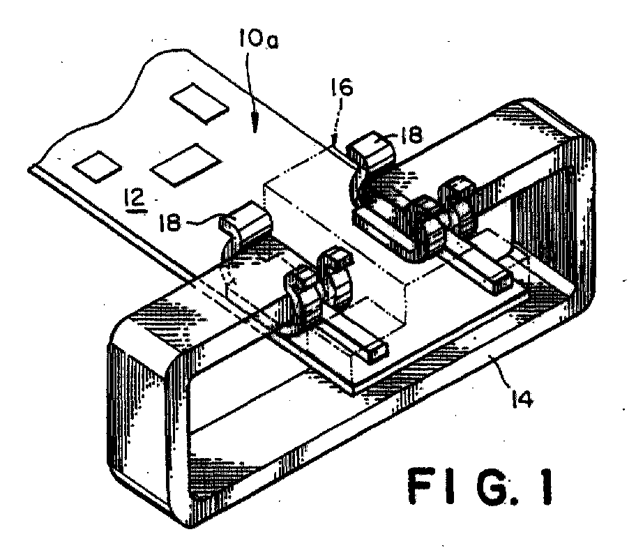
(57) An electrical connector (10a) is disclosed for being mounted on a board (12) and
for connecting a loop antenna (14) to a circuit on the board (12). The antenna connector
has a connector block and first and second terminals. The connector block (16) is
constructed from a non-conductive material and has opposing top and bottom faces (20t,
20b), first and second opposing side faces (22a, 22b), and a center portion extending
between the top face (20t) and bottom face (20b). The center portion defines first
and second bays (28a, 28b) isolated from each other, where the first and second bays
(28a, 28b) are exposed at the top and bottom faces. The first and second bays (28a,
28b) are further exposed, respectively, at the first side face and the second side
face. The first and second terminals (18) are mounted in the first and second bays
(28a, 28b) of the connector block (16). Each terminal is constructed from a conductive
material and has an open jaw positioned at the top face of the connector block, and
a contacting portion opposite the open jaw (30) and positioned at the bottom face
of the connector block (10). The antenna connector is mounted to the board such that
the bottom face (20b) of the connector block (16) faces the board (12), and such that
the contacting portions of the first and second terminals are in electrical contact
with corresponding pads on such board (12). The first and second terminals (18) respectively
receive a first end and a second end of the loop antenna.
|
|
