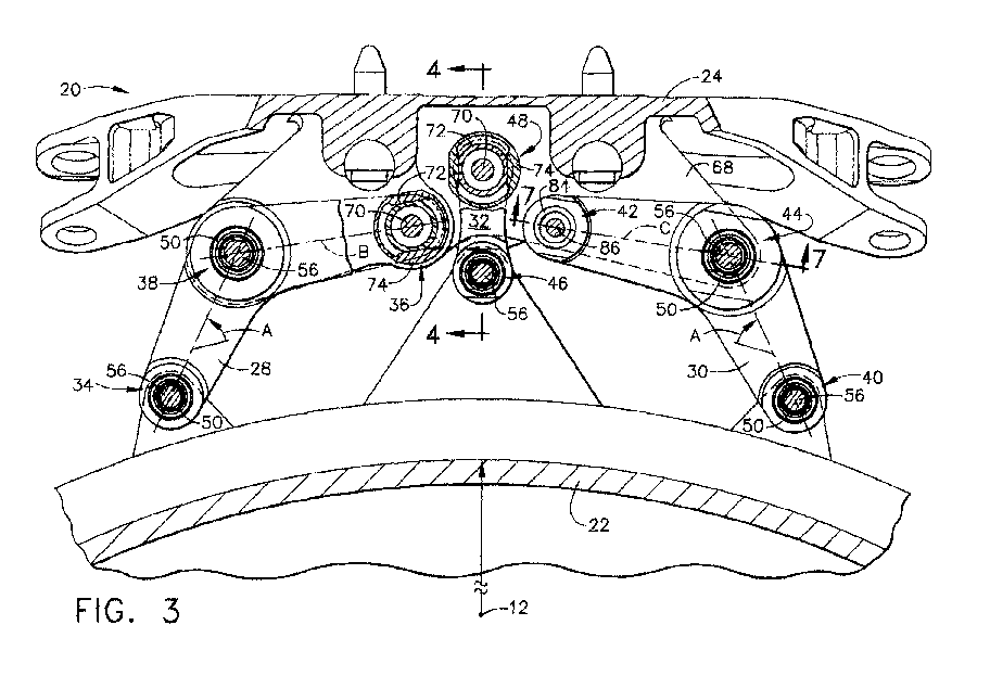
(57) An aircraft engine mount for mounting an engine to an aircraft includes a mounting
frame (24) fixedly joined to the aircraft, first and second prime links (28, 30) and
a waiting failsafe link (32). The first prime link (28) is joined to the engine at
a first joint (34) and to the mounting frame (24) at second and third joints (36,38).
The second prime link (30) is joined to the engine at a fourth joint (40) and to the
mounting frame (24) at fifth and sixth joints (42, 44). The waiting failsafe link
(32) is joined to the engine at a seventh joint (46) and to the mounting frame (24)
at an eighth joint (48). The first, third, fourth, sixth and seventh joints (34, 38,
40, 44, 46) are ball joints, and the second and eighth joints (36, 48) are translating
ball joints. The fifth joint (42) is a clearance pin joint. All of the translating
ball joints (36, 48) include a spherical bearing (62) disposed in an opening in the
respective link (28, 32) and a pin (70) extending through the spherical bearing (62).
An inner bushing (72) is disposed on the pin (70) and an outer bushing (74) disposed
over the inner bushing (72). The inner bushing (72) has an oppositely disposed set
of planar surfaces (76) formed on its outside diameter, and the outer bushing (74)
has an oppositely disposed set of axially extending planar surfaces (78) formed on
its inside diameter. Each one of the set of planar surfaces (78) formed on the outer
bushing (74) slidingly engages a corresponding one of the set of planar surfaces (76)
formed on the inner bushing (72).
|
|
