| (19) |
 |
|
(11) |
EP 1 137 579 B1 |
| (12) |
EUROPEAN PATENT SPECIFICATION |
| (45) |
Mention of the grant of the patent: |
|
06.04.2005 Bulletin 2005/14 |
| (22) |
Date of filing: 27.09.2000 |
|
| (51) |
International Patent Classification (IPC)7: B65D 75/58 |
| (86) |
International application number: |
|
PCT/GB2000/003699 |
| (87) |
International publication number: |
|
WO 2001/026992 (19.04.2001 Gazette 2001/16) |
|
| (54) |
PLASTIC BAG AND METHOD OF MAKING THE SAME
KUNSTSTOFFBEUTEL UND VERFAHREN ZU DESSEN HERSTELLUNG
SAC EN PLASTIQUE ET PROCEDE DE FABRICATION
|
| (84) |
Designated Contracting States: |
|
AT BE CH CY DE DK ES FI FR GB GR IE IT LI LU MC NL PT SE |
| (30) |
Priority: |
12.10.1999 GB 9923986
|
| (43) |
Date of publication of application: |
|
04.10.2001 Bulletin 2001/40 |
| (73) |
Proprietor: Supreme Plastics Holdings Limited |
|
Finchley
London N3 2TL (GB) |
|
| (72) |
Inventor: |
|
- LEIGHTON, Murray Edward Bruce
Finchley,
LondonN3 2TL (GB)
|
| (74) |
Representative: W.P. THOMPSON & CO. |
|
Eastcheap House
Central Approach
Letchworth Garden City,
Hertfordshire SG6 3DS
Letchworth Garden City,
Hertfordshire SG6 3DS (GB) |
| (56) |
References cited: :
EP-A- 0 779 222
US-A- 4 480 752
|
DE-A- 2 622 659
|
|
| |
|
|
|
|
| |
|
| Note: Within nine months from the publication of the mention of the grant of the European
patent, any person may give notice to the European Patent Office of opposition to
the European patent
granted. Notice of opposition shall be filed in a written reasoned statement. It shall
not be deemed to
have been filed until the opposition fee has been paid. (Art. 99(1) European Patent
Convention).
|
[0001] This invention relates generally to plastics bags, and particularly to plastics bags
which have been formed, filled and sealed. The invention is also concerned with methods
of manufacturing such bags to incorporate means by which they can easily be opened.
The invention is also concerned with tag material used as a means to facilitate the
opening of such bags.
[0002] Plastics bags which have been formed, filled and sealed are often difficult to open
because of the effectiveness of the seal. In many cases, the pulling force needed
on the sides of the bag to open the top seal is substantial.
[0003] It is an object of the present invention to provide means for more easily opening
sealed bags, especially those which have been formed, filled with contents and sealed.
[0004] It is also an object of the present invention to provide a method of manufacturing
a plastics bag to incorporate means for easy opening.
[0005] In accordance with one aspect of the present invention there is provided a plastics
bag comprising a pair of sides defining an openable mouth along one margin of the
sides, a seal extending parallel to said margin to close the sides, the inner surfaces
of the pair of sides facing each other, and a tag within a part of the seal which
can be withdrawn and used to open a zone of the seal to permit access to the interior
of the bag.
[0006] Preferably, the tag is positioned substantially centrally of the said margin of the
bag.
[0007] Preferably, the tag is folded to lie within the contour of the bag sides until withdrawn.
[0008] In a preferred embodiment, the tag is folded in a generally M-shaped configuration
in cross-section, with the outside surfaces of the outside legs of the tag being sealed
to the seal and/or to the sides of the bag, and with the inside legs being arranged
to be withdrawn from between the outside legs.
[0009] It is of assistance if the inside surfaces of the outside legs of the tag are in
peel seal engagement with the outside surfaces of the inside legs of the tag in said
M-shaped configuration.
[0010] The tag is preferably provided with a line of weakness, e.g. perforations, along
the junction of the inside legs of the tag.
[0011] In a preferred embodiment, the bag has two seals extending parallel to the said margin,
one of which is a reclosable zipper seal.
[0012] Preferably, the zipper seal has marginal flanges extending laterally from interengageable
male and female closure members, and the tag is sealed to the inside surfaces of flanges
extending from the closure members towards the mouth of the bag.
[0013] In accordance with another aspect of the present invention there is provided a method
of manufacturing a plastics bag comprising a prior of sides which includes providing
a seal parallel to a margin of the sides which defines an openable mouth, the inner
surfaces of the pair of sides facing each other, and incorporating into a part of
the seal a tag which can be withdrawn and used to open a zone of the seal to permit
access to the interior of the bag.
[0014] In one preferred method, the method includes sealing the tag to flanges of a reclosable
zipper seal having interengageable male and female closure members, sealing the zipper
seal and tag to a host material which is to form the sides of the bag, forming the
bag, and creating a second seal parallel to said margin, on the side of the zipper
seal which is closer to the mouth of the bag, with the tag extending through the second
seal.
[0015] In an alternative method, the method includes sealing the tag to a host material
which is to form the sides of the bag, forming the bag, and creating the seal parallel
to said margin with the tag extending through the seal.
[0016] It will therefore be appreciated that the present invention can be used both with
bags which incorporate a reclosable zipper seal along with the top seal, and also
with bags which have a top seal only.
[0017] Also in accordance with the invention there is provided tag material comprising an
elongate strip comprising a first layer having an outside surface suitable to be sealed
to a web of plastics material and a second layer having an outside surface having
peel-seal properties, wherein the strip is folded about its longitudinal axis into
a generally M-shaped configuration with the first layer on the outside and with the
outer legs of the folded strip extending beyond the tuck.
[0018] The tag which is used as the agent by which the seal can be broken and the bag opened
is preferably a piece of laminated material. The laminated material preferably comprises
an outer layer to be sealed to the host film, a layer to provide the tag with strength,
a layer to provide the tag with thermal insulation and a peel seal layer.
[0019] The method of manufacturing a bag in accordance with the invention is particularly
appropriate for use with a zipper strip applied transversely to the direction of advance
of the host material, i.e. using cross-web technology.
[0020] In order that the invention may be more fully understood, a number of presently preferred
embodiments will now be described by way of example and with reference to the accompanying
drawings. In the drawings:
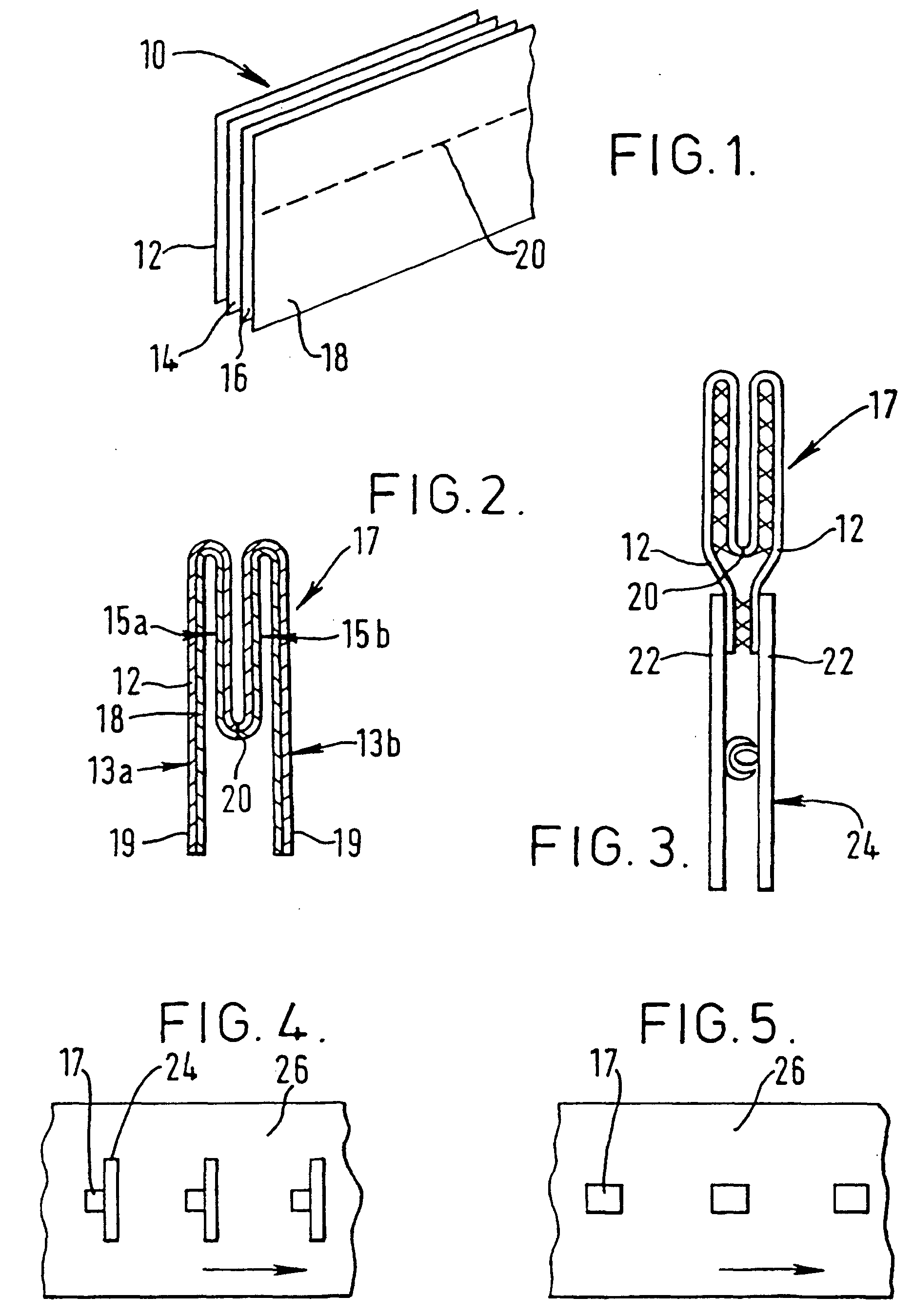
Fig. 1 shows the structure of a laminated material suitable for use as a tag in accordance
with the present invention;
Fig. 2 shows the laminated material folded to make a tag;
Fig. 3 is a sectional view showing the insertion of a folded tag into a zipper strip;
Fig. 4 shows the zipper strip and tag sealed to a host material;
Fig. 5 shows a modified embodiment where just the folded tag is sealed to the host
material;
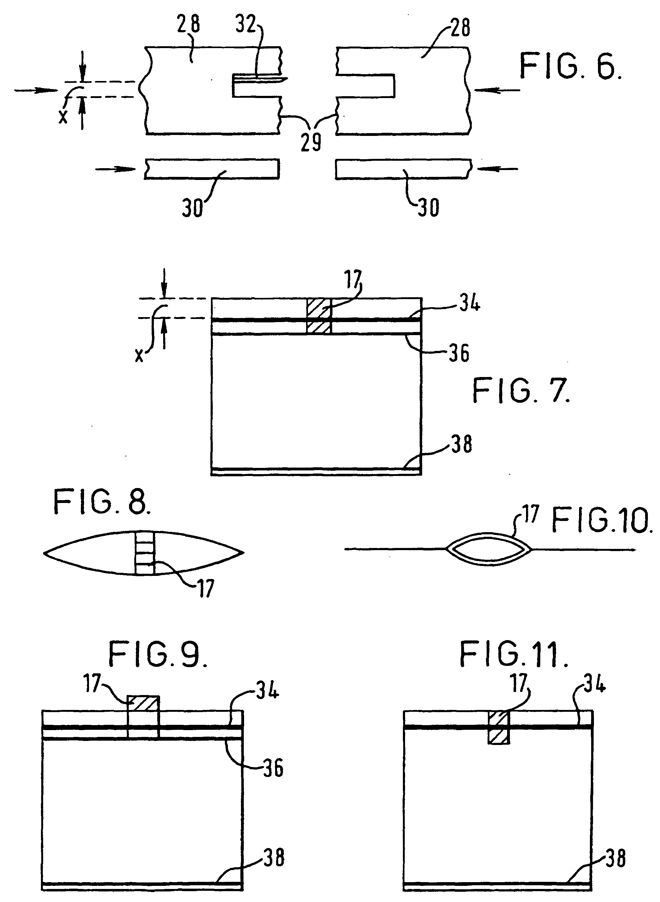
Fig. 6 is a schematic view of a sealing jaw construction on a form-fill-seal machine
for use in the method according to the present invention;
Fig. 7 is a front view of a bag in accordance with the invention provided with a top
seal, a zipper seal and a tag;
Fig. 8 is a top view of the bag of Fig. 7;
Fig. 9 shows the bag of Fig. 7 with the tuck of the tag withdrawn;
Fig. 10 shows the bag of Fig. 9 with the tag opened; and
Fig. 11 is a front view of a bag in accordance with the invention provided with just
a top seal and a tag.
[0021] Referring first to Fig. 1 there is shown a laminated material 10 for use in making
tags for use in bags in accordance with the invention. The material 10 comprises an
outer layer 12 of a material suitable to be sealed to a host material, i.e. a plastics
film. One suitable material is polyethylene. Next to the polyethylene layer 12 is
a layer 14 to give the laminate strength. This can be of polyethylene terephthalate
(PET)material. There is then a layer 16, for example of foil material, to give the
laminate heat insulation properties. Next to this layer is a layer 18 of material
which has peel seal properties. These layers are bonded together. A line of perforations
20 is provided centrally along the length of the laminate material to provide a line
of weakness. These perforations can be holes or slits through the laminate.
[0022] The laminate material 10 can be stored on a roll. The laminate material is folded,
as shown in Fig. 2, substantially into an "M" shape, with two outer legs 13a, 13b
and two inner legs 15a, 15b which form an inner tuck. In Fig. 2 is shown an embodiment
of tag material which has only the two layers 12 and 18. Each of the intermediate
layers 14 and 16 of Fig. 1 can be regarded as optional, although desirable. The outer
legs extend down beyond the tuck and the line of perforations 20 is then at the bottom
of the tuck, i.e. at the junction of the inner legs 15a, 15b. The material can be
stored on a roll already doubled over about the perforation line 20 and with the tuck
folded in and with the peel seal layer surfaces which are then facing one another
welded together. The facing surfaces of peel seal material are sealed together, as
represented by the "crosses" in Fig. 3. Alternatively, the peel seal layer surfaces
can be welded together at a subsequent stage in the manufacture of the bag.
[0023] A section of the folded laminated material 10 is fed into an applicator and is cut
to length to make a tag 17. Adhesive is then applied to the outer faces 19 of the
outer layer 12 in the region of the outer legs 13a, 13b which extend beyond the tuck
and the tag 17 is then inserted between the top flanges 22 of a cross web zipper 24
as shown in Fig. 3. The adhesive thus sticks the tag 17 to the zipper 24.
[0024] In one embodiment of form-fill-seal machine, the zipper 24 and tag 17 are then sealed
jointly to the host material 26 as shown in Fig. 4. The host material 26 is a length
of plastics film or web from which the bag is to be made. They can be applied to the
film using a cross web technique, and sealed in position. This is done if the bag
is to have both a top seal and a zipper seal.
[0025] If the final bag is not to include a zipper seal, but only a top seal, then the folded
tag 17 is not affixed to a zipper strip as shown in Fig. 3, but is sealed by itself
to the host material 26, as shown in Fig. 5. The tags 17 are positioned at appropriate
intervals along the length of the advancing host material 26.
[0026] The host material 26 carrying the zippers and tags (Fig. 4), or the tags alone (Fig.
5), is then run as normal through a form-fill-seal machine including passage over
a forming shoulder. Fig. 6 shows the sealing jaw construction used to seal the bag
after filling when the bag is to incorporate both a zipper seal and a top seal. The
sealing jaw construction comprises upper sealing jaws 28 and zipper sealing jaws 30.
The upper jaws 28 incorporate impulse or resistance heating means in their facing
surfaces 29 to effect the required top seal. The web material 26 is thereby sealed
to itself along the greater part of the width of the bag, but in the area of the tag
17 the web material 26 is sealed to those parts of the outside surfaces of the outer
legs 13a, 13b of the tag which are in alignment with the tuck. Similarly, the lower
jaws 30 effect the sealing of the zipper seal flanges to the web material 26. The
jaws also incorporate a knife 32 to sever the bags. In Fig. 5 there is indicated a
spacing x. This is the minimum distance required to incorporate the tag. Upon the
top end seal of the bag being made by the jaws 28, the tag 17 protrudes through the
seal with the outer portions of the tag sealed to the host film. This is illustrated
in Fig. 7 which shows the bag construction. Here there is a top seal 34 and a zipper
seal 36 and a bottom seal 38. The tag is sandwiched between the webs of the film and
the distance between the top seal 34 and the top end of the bag is again x as in Fig.
6. This distance x can be approximately 5 millimetres.
[0027] If the bag incorporates no zipper seal 36, but only a top seal 34, then the tag 17
will simply protrude from the top seal 34, as shown in Fig. 11.
[0028] Fig. 8 shows a top view of the bag with the tag 17 in the centre of the seal.
[0029] In order to open the sealed bag the tucked-in portion of the tag is pulled up by
a finger as shown in Fig. 9, with the peel seals opening. This creates a protruding
loop. A finger can then be inserted into the loop of the tag to break the perforations
20. This creates two protruding flaps. When the two flaps of the tag which are thus
created are pulled apart the peel seal material of the tag overlaid by seal 34, and
by seal 36 if present, will give, allowing entry to the inside of the bag through
the opened tag, as shown in Fig. 10. The opening of the peel seal material gives an
access hole through the top seal 34, and through the zipper seal 36 if provided, directly
to the interior of the bag. The opening can then be enlarged.
1. A plastics bag comprising a pair of sides defining an openable mouth along one margin
of the sides, a seal (34) extending parallel to said margin to close the sides, the
inner surfaces of the pair of sides facing each other, and a tag (17) within a part
of the seal which can be withdrawn and used to open a zone of the seal to permit access
to the interior of the bag.
2. A bag according to claim 1, in which the tag is positioned substantially centrally
of the said margin of the bag.
3. A bag according to claim 1 or 2, in which the tag; is folded to lie within the contour
of the bag sides until withdrawn.
4. A bag according to any preceding claim, in which the tag is folded in a generally
M-shaped configuration in cross-section, with the outside surfaces of the outside
legs (13a, 13b) of the tag being sealed to the seal (34) and/or to the sides of the
bag, and with the inside legs (15a, 15b) being arranged to be withdrawn from between
the outside legs (13a, 13b).
5. A bag according to claim 4, in which the inside surfaces of the outside legs (13a,
13b) of the tag are in peel seal engagement with the outside surfaces of the inside
legs (15a, 15b) of the tag in said M-shaped configuration.
6. A bag according to claim 4 or 5, in which only the outside legs of the tag extending
beyond the inside legs are sealed to the seal.
7. A bag according to claim 4, 5 or 6, in which the tag is provided with a line of weakness
(20) along the junction of the inside legs (15a, 15b) of the tag.
8. A bag according to claim 7, in which the line of weakness comprises a row of perforations.
9. A bag according to any preceding claim, in which the tag is made of a laminated material
10. A bag according to claim 9, in which the laminated material comprises at least three
layers.
11. A bag according to claim 10, in which the laminated material (10) comprises four layers,
a first layer (12) of a material which is sealable to a plastics film, a second layer
(14) of a relatively strong material, a third layer (16) which has heat relatively
strong material, a third layer which has heat insulating properties and a fourth layer
(18) of peel seal material.
12. A bag according to any preceding claim, which has two seals extending parallel to
the said margin, one of which is a reclosable zipper seal (36).
13. A bag according to claim 12, in which the reclosable zipper seal (24, 36) is on the
inside in relation to the other seal (34), and the tag (17) is located within both
seals.
14. A bag according to claim 12 or 13, in which the zipper seal (24, 36) has marginal
flanges (22) extending laterally from interengageable male and female closure members,
and the tag (17) is sealed to the inside surfaces of flanges extending from the closure
members towards the mouth of the bag.
15. A method of manufacturing a plastics bag comprising a pair of sides which includes
providing a seal (34) parallel to a margin of the sides which defines an openable
mouth, the inner surfaces of the pair of sides facing each other; and incorporating
into a part of the seal a tag (17) which can be withdrawn and used to open a zone
of the seal to permit access to the interior of the bag.
16. A method according to claim 15, which includes sealing the tag to flanges (22) of
a reclosable zipper seal (24, 36) having interengageable male and female closure members,
sealing the zipper seal and tag (17) to a host material (26) which is to form the
sides of the bag, forming the bag, and creating a second seal (34) parallel to said
margin, on the side of the zipper seal (36) which is closer to the mouth of the bag,
with the tag extending through the second seal.
17. A method according to claim 15, which includes sealing the tag (17) to a host material
(26) which is to form the sides of the bag, forming the bag, and creating the seal
(34) parallel to said margin with the tag extending through the seal.
18. A method according to claim 15, 16 or 17, which includes folding a length of laminated
material into a generally M-shaped configuration in cross-section, and cutting off
a section of the folded material to form the tag.
19. A method according to claim 18, which includes providing a line of weakness (20) along
the junction of the inside legs of the tag.
20. A method according to any of claims 15 to 19, in which the tag is located on the host
material (26) so that the tag (17) lies within the contour of the bag sides when the
bag is completed and sealed.
21. Tag material comprising an elongate strip comprising a first layer (19) having an
outside surface suitable to be sealed to a web of plastics material and a second layer
(18) having an outside surface having peel-seal properties, wherein the strip is folded
about its longitudinal axis into a generally M-shaped configuration with the first
layer (19) on the outside and with the outer legs (13a, 13b) of the folded strip extending
beyond the tuck.
22. Tag material according to claim 21, in which a line of weakness (20) is provided along
the length of the strip so as to be located at the apex of the tuck when folded.
23. Tag material according to claim 22, in which the line of weakness (20) comprises a
row of perforations through the strip.
24. Tag material according to claim 21, 22 or 23, in which the strip also includes a layer
(14) of strengthening material between the first and second layers.
25. Tag material according to any of claims 21 to 24, in which the strip also includes
a layer (16) of heat insulating material between the first (19) and second layers
(18).
1. Kunststoffbeutel mit einem Seitenpaar, das eine aufmachbare Öffnung entlang eines
Randes der Seiten definiert, einem dichten Verschluß (34), der sich parallel zum Rand
erstreckt zum Schließen der Seiten, wobei sich die inneren Flächen des Seitenpaares
gegenüberliegen und mit einem Anhänger innerhalb eines Teils des dichten Verschlusses,
der zurückziehbar ist und zum Öffnen einer Zone des dichten Verschlusses verwendet
werden kann, um den Zugang in das Innere des Kunststoffbeutels zu gestatten.
2. Beutel nach Anspruch 1, wobei der Anhänger im wesentlichen zentral am Rand des Beutels
positioniert ist.
3. Beutel nach Anspruch 1 oder 2, wobei der Anhänger gefaltet innerhalb der Kontur der
Beutelseiten zu liegen kommt bis er zurückgezogen wird.
4. Beutel nach einem der vorangegangenen Ansprüche, in welchem der Anhänger im Querschnitt
in allgemeiner M-Form Konfiguration gefaltet wird wobei die äußeren Flächen der äußeren
Schenkel (13a,13b) des Anhängers dicht an den dichten Verschluß und/oder die Seiten
des Beutels angefügt sind und dessen innere Schenkel (15a,15b) zum Zurückziehen zwischen
den äußeren Schenkeln (13a,13b) vorgesehen sind.
5. Beutel nach Anspruch 4, in welchem die inneren Flächen der äußeren Schenkel (13a,13b)
des Anhängers wie ein Schälverschluß im Eingriff mit den Außenflächen der inneren
Schenkel (15a,15b) des Anhängers in besagter M-Form Konfiguration sind.
6. Beutel nach Anspruch 4 oder 5, bei welchem nur die äußeren Schenkel des Anhängers,
die sich zwischen den inneren Schenkeln erstrecken, an dem dichten Verschluß abgedichtet
sind.
7. Beutel nach Anspruch 4, 5 oder 6, bei welchem der Anhänger mit einer Schwächungslinie
(20) versehen ist, die entlang der Verbindung der inneren Schenkel (15a,15b) des Anhängers
verläuft.
8. Beutel nach Anspruch 7, bei welchem die Schwächungslinie eine Reihe von Perforationen
enthält.
9. Beutel nach einem der vorangegangenen Ansprüche, bei welchem der Anhänger aus laminierten
Material besteht.
10. Beutel nach Anspruch 9, bei welchem das laminierte Material mindestens drei Schichten
enthält.
11. Beutel nach Anspruch 10, bei welchem das laminierte Material (10) vier Schichten enthält,
eine erste Schicht (12) aus einem Material welches mit einem Kunststofffilm versiegelbar
ist, einer zweiten Schicht aus einem relativ starken Material, einer dritten Schicht
die wärmeisolierende Eigenschaften hat und einer vierten Schicht aus dem Material
eines Schälverschlusses.
12. Beutel nach einem der vorangegangenen Ansprüche, mit zwei Dichtungen, die sich parallel
zum Rand erstrecken und von denen eine ein wiederverschließbarer Reißverschluß (36)
ist.
13. Beutel nach Anspruch 12, bei welchem der wiederverschließbare Reißverschluß (24,36)
bezüglich des anderen Verschlusses (34) auf der Innenseite ist und der Anhänger innerhalb
beider Dichtungen sitzt.
14. Beutel nach Anspruch 12 oder 13, bei welchem der Reißverschluß (24,36) Randflansche
(22) enthält, die sich seitlich von zusammenwirkenden männlichen und weiblichen Verschlußgliedern
erstrecken, wobei der Anhänger (17) dicht mit den inneren Flächen der Flansche versiegelt
ist, die sich von den Verschlußgliedern gegen die Öffnung des Beutels erstrecken.
15. Verfahren zur Herstellung eines Kunststoffbeutels mit einem Seitenpaar, welches das
Vorsehen eines dichten Verschlusses (34) parallel zu einem Rand der Seiten einschließt,
welche eine aufmachbare Öffnung definieren, wobei sich die inneren Flächen des Seitenpaares
gegenüberliegen und in einem Teil des Verschlusses einen Anhänger (17) umfassen, der
zurückgezogen werden kann und zum Öffnen einer Zone des Verschlusses verwendbar ist
um Zutritt in das Innere des Beutels zu gestatten.
16. Verfahren nach Anspruch 15, welches das Abdichten des Anhängers an Flansche (22) eines
wiederverschließbaren Reißverschlusses (24,36) einschließt, welcher zusammenwirkende
männliche und weibliche Verschlußglieder besitzt sowie Abdichten des Reißverschlusses
und des Anhängers an einem Wirtsmaterial (26) zur Bildung der Seiten des Beutels,
Bildung des Beutels und Schaffung eines zweiten Verschlusses (34) parallel zu besagtem
Rand auf derjenigen Seite des Reißverschlusses (36), die näher an der Öffnung des
Beutels ist, wobei sich der Anhänger durch den zweiten Verschluß erstreckt.
17. Verfahren nach Anspruch 15, welches die Abdichtung des Anhängers (17) an dem Wirtsmaterial
(26) einschließt, welches zur Bildung der Seiten des Beutels dient, Bildung des Beutels
und Schaffung eines Verschlusses (34) parallel zu besagtem Rand, wobei sich der Anhänger
durch den Verschluß erstreckt.
18. Verfahren nach Anspruch 15,16 oder 17 einschließlich Faltung einer Länge aus laminiertem
Material in eine allgemein M-förmige Konfiguration im Querschnitt und Abschneiden
eines Abschnitts aus dem gefalteten Material zur Bildung des Anhängers.
19. Verfahren nach Anspruch 18, bei welchem eine Schwächungslinie (20) entlang der Verbindung
auf den Innenschenkeln des Anhängers vorgesehen ist.
20. Verfahren nach einem der Ansprüche 15 bis 19, bei welchem der Anhänger auf dem Wirtsmaterial
(26) so angeordnet ist, daß der Anhänger (17) innerhalb der Kontur der Beutelseiten
liegt, sobald der Beutel vervollständigt und verschlossen ist.
21. Material für einen Anhänger mit einem länglichen Streifen, der eine erste Schicht
(19) enthält, deren äußere Oberfläche zum Versiegeln auf einer Bahn aus Kunststoffmaterial
geeignet ist und eine zweite Schicht (18), deren äußere Oberfläche die Eigenschaften
eines Schälverschlusses hat, wobei der Streifen um seine Längsachse in eine allgemein
M-förmige Konfiguration mit der ersten Schicht (19) auf der Außenseite gefaltet wird,
wobei sich die Außenschenkel (13a,13b) des gefalteten Streifens jenseits der Falte
erstrecken.
22. Material für einen Anhänger nach Anspruch 21, bei welchem eine Schwächungslinie (20)
entlang der Länge des Streifens vorgesehen ist um beim Falten am Scheitelpunkt der
Falte angeordnet zu werden.
23. Material für einen Anhänger nach Anspruch 22, bei welchem die Schwächungslinie (20)
eine Reihe von Perforationen durch den Streifen enthält.
24. Material für einen Anhänger nach Anspruch 21,22 oder 23, bei welchem der Streifen
auch eine Schicht (14) aus Verstärkungsmaterial zwischen der ersten und zweiten Schicht
einschließt.
25. Material für einen Anhänger nach einem der Ansprüche 21 bis 24, bei welchem der Streifen
ebenfalls eine Schicht (16) aus wärmeisolierendem Material zwischen der ersten (19)
und zweiten Schicht (18) einschließt.
1. Sac en plastique comprenant une paire de côtés définissant une gueule ouvrable le
long d'un rebord des côtés, une fermeture (34) s'étendant parallèlement audit rebord
de manière à fermer les côtés, les surfaces internes de la paire de côtés se faisant
face, et une languette (17) à l'intérieur d'une partie de la fermeture, qui peut être
retirée et utilisée pour ouvrir une zone de la fermeture pour permettre l'accès à
l'intérieur du sac.
2. Sac selon la revendication 1, dans lequel la languette est positionnée de manière
sensiblement centrale par rapport au dit rebord du sac.
3. Sac selon la revendication 1 ou 2, dans lequel la languette est repliée pour reposer
à l'intérieur du contour des côtés du sac jusqu'à ce qu'elle soit retirée.
4. Sac selon l'une quelconque des revendications précédentes, dans lequel la languette
a une configuration sensiblement en forme de M en coupe transversale, les surfaces
extérieures des pattes extérieures (13a, 13b) de la languette étant fixées à la fermeture
(34) et/ou aux côtés du sac, et les pattes intérieures (15a, 15b) étant disposées
de manière à être retirées d'entre les pattes extérieures (13a, 13b).
5. Sac selon la revendication 4, dans lequel les surfaces intérieures des pattes extérieures
(13a, 13b) de la languette sont en engagement de fermeture pelable avec les surfaces
extérieures des pattes intérieures (15a, 15b) de la languette dans ladite configuration
en forme de M.
6. Sac selon la revendication 4 ou 5, dans lequel uniquement les pattes extérieures de
la languette s'étendant au-delà des pattes intérieures sont fixées à la fermeture.
7. Sac selon la revendication 4, 5 ou 6, dans lequel la languette est munie d'une ligne
de faiblesse (20) le long de la jonction des pattes intérieures (15a, 15b) de la languette.
8. Sac selon la revendication 7, dans lequel la ligne de faiblesse comprend une rangée
de perforations.
9. Sac selon l'une quelconque des revendications précédentes, dans lequel la languette
est faite d'un matériau stratifié.
10. Sac selon la revendication 9, dans lequel le matériau stratifié comprend au moins
trois couches.
11. Sac selon la revendication 10, dans lequel le matériau stratifié (10) comprend quatre
couches, une première couche (12) faite d'un matériau scellable sur un film plastique,
une deuxième couche (14) faite d'un matériau relativement résistant, une troisième
couche (16) qui a des propriétés d'isolation thermique et une quatrième couche (18)
de matériau de fermeture pelable.
12. Sac selon l'une quelconque des revendications précédentes, qui présente deux fermetures
s'étendant parallèlement au dit rebord, l'une desquelles étant une fermeture à glissière
à pression (36).
13. Sac selon la revendication 12, dans lequel la fermeture à glissière à pression (24,
36) est située à l'intérieur par rapport à l'autre fermeture (34), et la languette
(17) est située à l'intérieur des deux fermetures.
14. Sac selon la revendication 12 ou 13, dans lequel la fermeture à glissière (24, 36)
a des brides marginales (22) s'étendant latéralement à partir d'éléments de fermeture
emboîtables mâle et femelle, et la languette (17) est fixée aux surfaces intérieures
de brides s'étendant à partir des éléments de fermeture vers la gueule du sac.
15. Procédé de fabrication d'un sac en plastique comprenant une paire de côtés, comprenant
les étapes consistant à apporter une fermeture (34) parallèlement à un rebord des
côtés qui définit une gueule ouvrable, les surfaces internes de la paire de côtés
se faisant face, et à incorporer dans une partie de la fermeture une languette (17)
qui peut être retirée et utilisée pour ouvrir une zone de la fermeture afin de permettre
l'accès à l'intérieur du sac.
16. Procédé selon la revendication 15, comprenant les étapes consistant à fixer la languette
à des brides (22) d'une fermeture à glissière à pression (24, 36) ayant des éléments
de fermeture emboîtables mâle et femelle, à fixer la fermeture à glissière et la languette
(17) à un matériau d'accueil (26) qui est destiné à former les côtés du sac, à former
le sac, et à créer une seconde fermeture (34) parallèle au dit rebord, sur le côté
de la fermeture à glissière (36) qui est le plus proche de la gueule du sac, la languette
s'étendant à travers la seconde fermeture.
17. Procédé selon la revendication 15, comprenant les étapes consistant à fixer la languette
(17) à un matériau d'accueil (26) qui est destiné à former les côtés du sac, à former
le sac, et à créer la fermeture (34) parallèlement au dit rebord, la languette s'étendant
à travers la fermeture.
18. Procédé selon la revendication 15, 16 ou 17, comprenant les étapes consistant à plier
une longueur de matériau stratifié en une configuration sensiblement en forme de M
en coupe transversale, et à découper une partie du matériau plié pour former la languette.
19. Procédé selon la revendication 18, comprenant l'étape consistant à apporter une ligne
de faiblesse (20) le long de la jonction des pattes intérieures de la languette.
20. Procédé selon l'une quelconque des revendications 15 à 19, dans lequel la languette
est positionnée sur le matériau d'accueil (26) de sorte que la languette (17) repose
à l'intérieur du contour des côtés du sac lorsque le sac est achevé et scellé.
21. Matériau de languette, comprenant une bande allongée comprenant une première couche
(19) ayant une surface extérieure adaptée pour être fixée à une toile de matériau
plastique et une deuxième couche (18) ayant une surface extérieure ayant des propriétés
de fermeture pelable, dans lequel la bande est repliée sur son axe longitudinal en
une configuration sensiblement en forme de M, la première couche (19) étant à l'extérieur
et les pattes extérieures(13a, 13b) de la bande repliée s'étendant au-delà du pli.
22. Matériau de languette selon la revendication 21, dans lequel une ligne de faiblesse
(20) est apportée le long de la longueur de la bande, de manière à être positionnée
au sommet du pli lorsque la bande est repliée.
23. Matériau de languette selon la revendication 22, dans lequel la ligne de faiblesse
(20) comprend une rangée de perforations à travers la bande.
24. Matériau de languette selon la revendication 21, 22 ou 23, dans lequel la bande comprend
également une couche (14) de matériau de renforcement entre la première et la deuxième
couche.
25. Matériau de languette selon l'une quelconque des revendications 21 à 24, dans lequel
la bande comprend également une couche (16) de matériau d'isolation thermique entre
la première couche (19) et la deuxième couche (18).