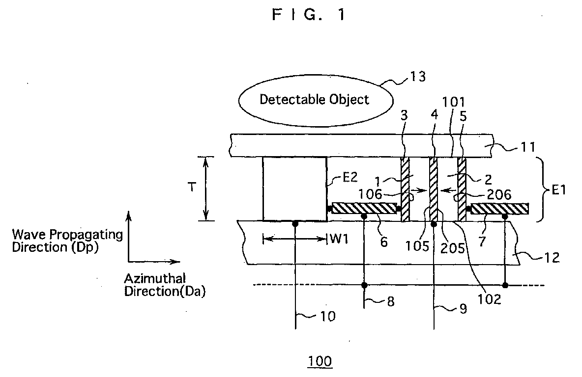
(57) Herein disclosed is a sound converting apparatus for performing conversion between
electric signals and ultrasonic waves, comprising: a plurality of oscillation bodies
E1, E2 for emitting ultrasonic waves converted from the electric signals along a wave
propagating direction Dp; and a plurality of electrically conductive bodies 6,7 each for electrically connecting
the oscillation bodies E1, E2; a plurality of signal lines 9, 10 for inputting electric
signals to be applied to respective oscillation bodies E1, E2; a pair of external
electrodes 3, 5 respectively held in contact with the outer surfaces 106, 206 of respective
piezoelectric layers 1, 2 and electrically connected with the electrically conductive
bodies 6, 7; and a dividing electrode 4 sandwiched by and held in contact with the
inner surfaces 105, 205 of the piezoelectric layers 1, 2 and electrically connected
with the signal line 9, whereby the piezoelectric layers 1, 2 respectively generate
electric polarizations, directions of which are opposing to each other and extending
substantially parallel to an azimuthal direction Da perpendicular to the wave propagating direction Dp, and emit ultrasonic waves converted from the electric signals along the wave propagating
direction Dp when electrical fields are applied between the external electrodes 3, 5 and the dividing
electrode 4 in response to the electric signals, the ratio of the width W1 to the
thickness T is within a range of from 0.1 to 0.8.
|
|
