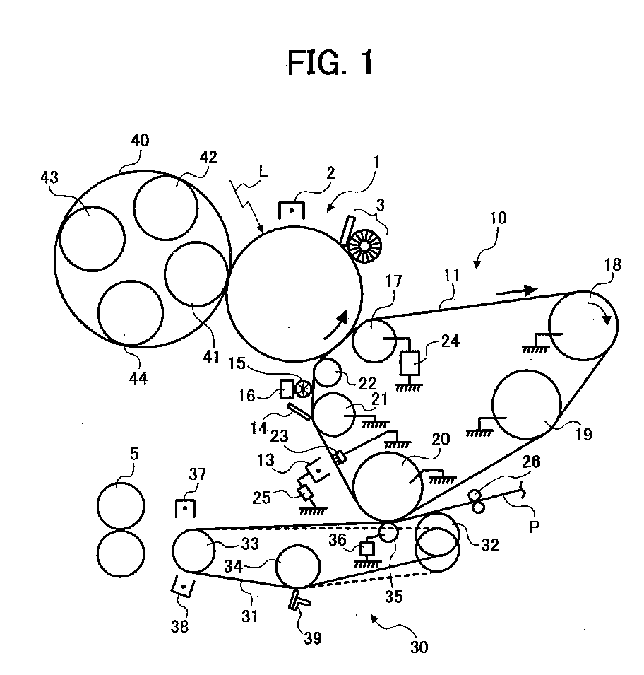
(57) In an image forming apparatus including an image carrier (1, 100Bk, 100Y, 100M, 100C)
that carries a visual image formed thereon, an intermediate transfer element (11,
111) that moves and receives the visual image from the image carrier (1, 100Bk, 100Y,
100M, 100C), a primary transfer device (17, 56Bk, 56Y, 56M, 56C) that transfers the
visual image from the image carrier (1, 100Bk, 100Y, 100M, 100C) onto the intermediate
transfer element (11, 111), a secondary transfer device (35, 55) that transfers the
visual image on the intermediate transfer element (11, 111) onto a recording material,
a cleaning device (14, 114) that mechanically removes developer remaining on the intermediate
transfer element (11, 111) and that is brought into contact with and separated from
the intermediate transfer element (11, 111), and a discharging device (13, 113) that
discharges the intermediate transfer element (11, 111), the discharging device (13,
113) is arranged downstream of the secondary transfer device (35, 55) and upstream
of the cleaning device (14, 114) in a moving direction of the intermediate transfer
element (11, 111), and preferably a grounding member (23, 123) is provided at a rear
side of the intermediate transfer element (11, 111) such that the grounding member
(23, 123) opposes the discharging device (13, 113) via the intermediate transfer element
(11, 111).
|
|
