| (19) |
 |
|
(11) |
EP 1 328 769 B1 |
| (12) |
EUROPEAN PATENT SPECIFICATION |
| (45) |
Mention of the grant of the patent: |
|
22.02.2012 Bulletin 2012/08 |
| (22) |
Date of filing: 03.09.2001 |
|
| (51) |
International Patent Classification (IPC):
|
| (86) |
International application number: |
|
PCT/SE2001/001867 |
| (87) |
International publication number: |
|
WO 2002/021070 (14.03.2002 Gazette 2002/11) |
|
| (54) |
METHOD FOR SPEED COMPENSATION OF A SHAPED CHARGE JET, AND MISSILE
VERFAHREN FÜR DEN GESCHWINDIGKEITSAUSGLEICH EINES HOHLLADUNGSSTRAHLES UND FLUGKÖRPER
PROCEDE DE COMPENSATION DU JET D'UNE CHARGE PROFILEE ET MISSILE
|
| (84) |
Designated Contracting States: |
|
AT BE CH CY DE DK ES FI FR GB GR IE IT LI LU MC NL PT SE TR |
| (30) |
Priority: |
04.09.2000 SE 0003107
|
| (43) |
Date of publication of application: |
|
23.07.2003 Bulletin 2003/30 |
| (73) |
Proprietor: Saab AB |
|
581 88 Linköping (SE) |
|
| (72) |
Inventor: |
|
- HELANDER, Jyrki
S-632 33 Eskilstuna (SE)
|
| (74) |
Representative: Falk, Bengt |
|
Saab Bofors Support AB
Patents and Trademarks
691 80 Karlskoga
691 80 Karlskoga (SE) |
| (56) |
References cited: :
DE-A1- 3 529 897
DE-A1- 19 813 376
DE-C1- 3 150 153
DE-C1- 3 605 579
GB-A- 2 170 888
|
DE-A1- 19 516 341
DE-C1- 977 835
DE-C1- 3 216 142
GB-A- 2 149 066
SE-B- 450 416
|
|
| |
|
|
|
|
| |
|
| Note: Within nine months from the publication of the mention of the grant of the European
patent, any person may give notice to the European Patent Office of opposition to
the European patent
granted. Notice of opposition shall be filed in a written reasoned statement. It shall
not be deemed to
have been filed until the opposition fee has been paid. (Art. 99(1) European Patent
Convention).
|
[0001] The present invention relates to a method for attacking a target by means of a missile
with at least one shaped charge, the direction of action of which differs from the
direction of flight of the missile, in which the direction of a jet of the shaped
charge is corrected for the speed of the missile. The invention also relates to a
missile comprising at least one shaped charge arranged to act in a direction that
differs from the direction of flight of the missile, which shaped charge is provided
with a correction device for correcting the direction of a jet of the shaped charge
based on the different directions of movement of the missile and the shaped charge
jet. A missile according to the above is well suited, for example, for attacking the
weaker parts of a tank, that is the upper side.
[0002] In
GB 2 006 400 and
GB 2 006 935 the introduction of speed compensation of a shaped charge jet with a direction of
action which differs from the direction of flight of the missile is already known.
The speed compensation that is introduced is of the same order of magnitude irrespective
of the speed of the missile when it reaches the target. Such speed compensation achieves
its objectives in the case when the speed of the missile in the direction of flight
remains within a narrow range of speeds for which the speed compensation has been
designed. If, however, the missile is designed to approach a target with changing
speeds in the direction of flight, its lethality will be greatly lessened outside
this narrow range of speeds.
[0003] From
DE 3605579 C, which forms a starting point for the preamble of independent claims 1 and 8, a missile
is disclosed with at least one shaped charge, the direction of which differs from
the flight direction of the missile. The jet of the shaped charge is corrected for
the speed of the missile in that the shaped charge is pivotal in a ball joint.
[0004] The object of the present invention is to achieve a method that provides the missile
with great lethality within a wide range of speeds, and a missile that has great lethality
within a wide range of speeds.
[0005] The object of the invention is achieved by a missile having the features of the characterizing
part of claim 8 and a method characterized in that the direction of the shaped charge
jet is designed to be adjustable relative to the shaped charge, and by a missile characterized
in that the correction device of the missile is designed to be able to adjust the
direction of the shaped charge jet relative to the shaped charge. By making the speed
compensation adjustable, the direction of the missile's shaped charge jet is adjusted
to the speed of the missile, and good lethality is achieved within a wide range of
speeds of the missile.
[0006] According to the invention, the speed of the missile is measured during its flight
towards the target, and the correction of the direction of the shaped charge jet is
carried out based on the measured speed of the missile. According to an advantageous
embodiment, the speed of the missile can suitably be obtained by measuring its acceleration
and integrating. The correction can be carried out in one or more steps during the
flight of the missile. Alternatively, the correction can be carried out continuously
during the flight of the missile. The demands for precision of correction, reliability,
cost, etc, can determine the correction method.
[0007] According to another advantageous method, the correction is carried out in the missile's
launcher before the missile is launched, based on information concerning, among other
things, the distance to the target. The method is based on knowing the missile's speed
pattern relatively well in advance and therefore being able to pre-set the correction
that applies for the speed of the missile when it reaches the target, as the distance
to the target is known. The speed of the missile does not therefore need to be measured
in this method. In order to achieve a more reliable correction, further information
can be provided, such as information about the speed of the target, temperature of
the missile or of the launcher, wind conditions or special characteristics of the
weapon.
[0008] The correction device incorporated in the missile can be designed in many ways in
order to achieve the intended correction of the direction of the shaped charge jet
of the missile. Particularly recommended are the introduction of a movable initiation
point, the incorporation of an external movable mask, the division of the shaped charge
into two parts that can move in relation to each other, the incorporation of a movable
shaped charge cone, the incorporation of a waveguide arranged in the shaped charge,
which waveguide is designed with a cavity within which an element can be moved.
[0009] Movements of the correction device can similarly be achieved in various ways. Particularly
recommended are the introduction of one or more electric motors arranged in the missile,
such as stepping motors, the incorporation of a propulsive element such as gunpowder,
the incorporation of magnets or the incorporation of pneumatic or hydraulic systems.
[0010] Other further developments will be apparent from the patent claims attached to the
description.
[0011] In the following, the invention will be described in greater detail in exemplified
form, with reference to the attached figures, in which:
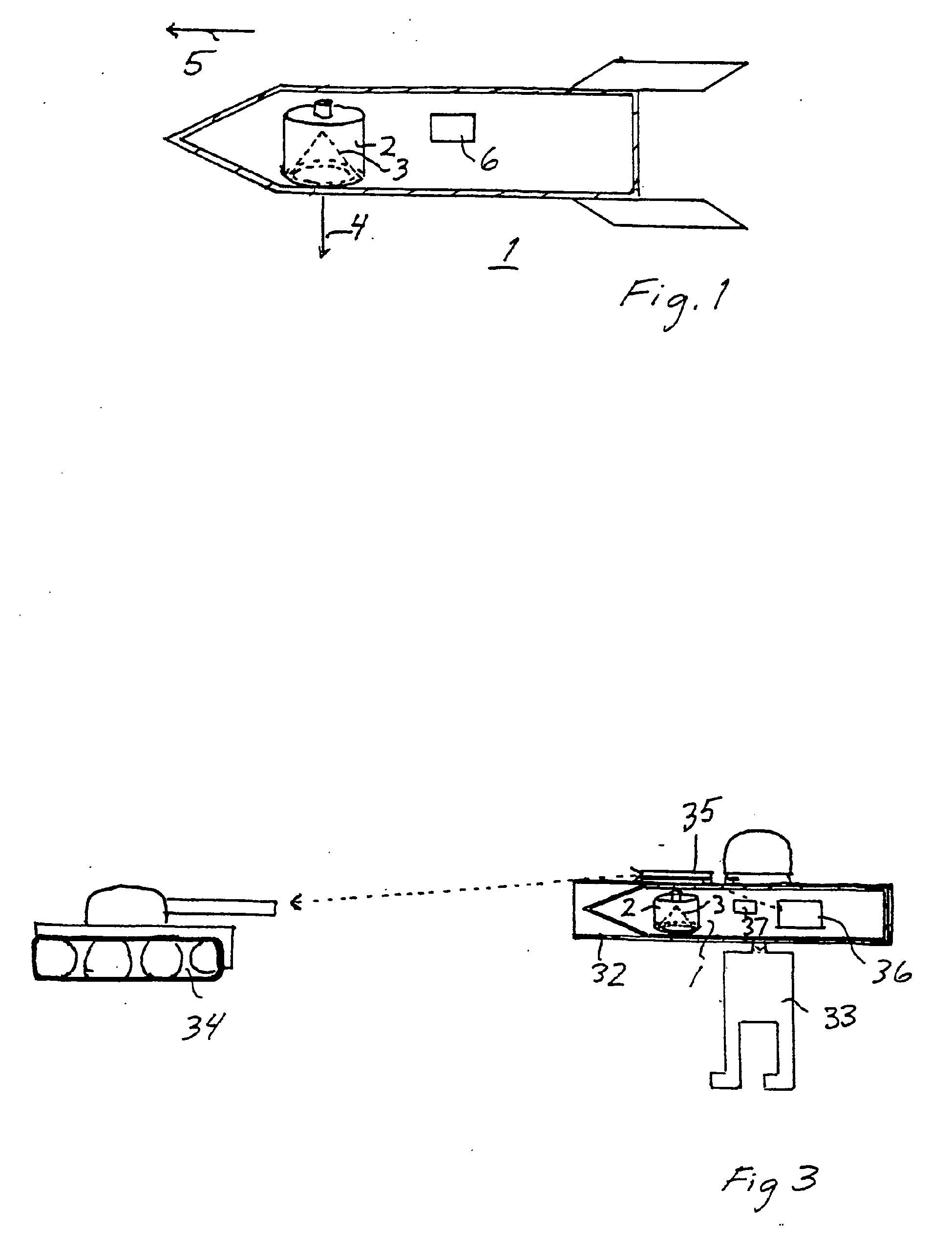
Figure 1 shows schematically an example according to the invention of a missile with
speed compensation of the shaped charge jet.
Figures 2a-2e show schematically five different ways of achieving adjustable speed
compensation of the jet of a shaped charge.
Figure 3 shows a further example according to the invention of a missile with speed
compensation of the shaped charge jet, in which the missile is shown in an associated
launcher and is directed towards a target.
[0012] The missile 1 shown in Figure 1 comprises a shaped charge 2 with a shaped charge
cone 3 directed so that the shaped charge jet leaves the missile 1 in a direction
4 essentially at right angles to the direction of flight 5 of the missile. In the
missile 1 there is a device 6 which records the speed of the missile during the flight.
The speed-recording device can, for example, consist of an accelerometer with signal
integration. Another alternative for measuring the speed is to use a gyro or turbine.
[0013] Figure 2a shows a first example of adjustable speed compensation. For the shaped
charge 2 in this case, the adjustment is achieved by means of the initiation point
7 of the shaped charge being arranged to be able to be moved above the tip of the
shaped charge cone 3. Arrows 8-12 indicate the possible movements that the initiation
point 7 can make.
[0014] Figure 2b shows another example of adjustable speed regulation. In this case, an
external mask 13 is arranged on the outside of the shaped charge 2. By moving the
mask 13 relative to the shaped charge 2 in directions that are indicated by the arrows
14-17, adjustment of the direction of the shaped charge jet is achieved.
[0015] In the embodiment shown in Figure 2c, the shaped charge 2 is divided with two parts
2.1 and 2.2 with a dividing plane 18 above the shaped charge cone 3. Arrows 19-21
indicate how the partial charge 2a can be moved in relation to the partial charge
2b.
[0016] The embodiment shown in Figure 2d has a shaped charge cone 3 that can be moved within
the shaped charge 2. Arrows 22-26 indicate how the shaped charge cone can be moved.
[0017] In the proposed embodiment according to Figure 2e, the waveguide 27 of the shaped
charge is used. The waveguide is designed with a cavity 28 with a movable element
29 inside the cavity. The movement of the element 29 is determined by the speed of
the missile. The function of the element 29 is to locally increase the shock-wave
speed in order thereby to create a penetration of the detonation front in the waveguide.
The asymmetry created by the element 29 is expected to give a speed-compensated shaped
charge jet. Arrows 30 and 31 indicate how the element 29 and the waveguide 27 can
move.
[0018] It can be pointed out here that the embodiments according to the Figures 2a-2d also
normally comprise waveguides. As these waveguides have no particular effect on the
adjustable correction of the shaped charge jet, they have been omitted in the figures.
[0019] The movements described with reference to the Figures 2a-2e can be achieved in many
ways. For example, an electric motor can be used, and for correction in steps a stepping
motor is particularly suitable. It is also possible to use some form of propulsive
element, for example a powder charge. Movement can also be achieved by means of (electro-)magnets.
Other methods of achieving movement can be based on pneumatics or hydraulics.
[0020] In the following, a further embodiment of the missile 1 is described, where the correction
that is to be introduced into the missile's shaped charge jet is set before launching,
that is when the missile is inside the launcher 32 from which it is to be fired.
[0021] Figure 3 shows an operator 33 who is aiming the weapon at a target 34 in the form,
for example, of a tank. The operator uses a range-finder 35 arranged on the outside
of the launcher 32. The missile 1 is inside the launcher 32 and comprises a shaped
charge 2. The range-finder 35, which can be independent, provides information about
the distance to the target 34 and may also measure the target's speed. There can be
equipment in the missile 1 or its launcher 32 for measuring temperature. A wind-speed
meter and a timer can also be included. In the figure, the equipment for measuring
temperature and wind and the timer are shown contained in a common housing 36.
[0022] The weapon works as follows. When the operator aims at the target, information is
obtained about at least the distance to the target. Based on the distance information
and any other information, for example as above, the speed of the missile when it
approaches the target can be estimated and hence the correction of the direction of
the shaped charge can be adjusted before launching. The above applies on the assumption
that the speed of the missile as a function of the distance covered is known. The
processing of the available information and the estimation of the speed can be carried
out in a processing unit 37 housed in the missile 1. When the missile leaves the launcher,
the shaped charge is thus adjusted to provide the optimal lethality.
[0023] The invention is not limited to the embodiments described above, but can be modified
within the scope of the following patent claims.
1. A method for attacking a target by means of a missile (1) with at least one shaped
charge (2), the direction of action of which differs from the direction of flight
of the missile (1), in which the direction of a jet of the shaped charge is corrected
for the speed of the missile (1), characterized in that the direction of the shaped charge jet is designed to be adjustable relative to the
shaped charge (2) and in that the speed of the missile during its flight towards the target is measured (6) and
in that the correction of the direction of the shaped charge jet is carried out on the basis
of the measured speed of the missile.
2. A method according to any one of the preceding claims, characterized in that the speed of the missile is measured by measuring its acceleration and integrating
(6).
3. A method according to any one of the preceding claims, characterized in that the correction for the speed of the missile (1) is carried out in one or more steps
during the flight of the missile.
4. A method according to any one of Claim 1, characterized in that the correction for the speed of the missile (1) is carried out continuously during
the flight of the missile.
5. A method according to Claim 1, characterized in that the correction is carried out in the missile's launcher (32) before the missile (1)
is launched, based among other things on information about the distance to the target.
6. A method according to Claim 5, characterized in that, in addition to information about the distance to the target, the correction is based
on at least one of the following, namely information about the speed of the target,
temperature in the missile (1) or launcher (32), wind conditions or special characteristics
of the weapon.
7. A missile (1) comprising at least one shaped charge (2) arranged to act in a direction
(4) that differs from the direction of flight (5) of the missile, which shaped charge
(2) is provided with a correction device (7 in fig.2a; 13 in fig 2b; 2.1 in fig 2c;
3 in fig. 2d; 28-29 in fig. 2e) for correcting the direction of a jet of the shaped
charge on the basis of the different directions of movement of the missile (1) and
the shaped charge jet, characterized in that the missile's correction device is designed to be able to adjust the direction of
the shaped charge jet relative to the shaped charge (2).
8. A missile according to Claim 7, characterized in that the correction device comprises an initiation point for the shaped charge which is
designed to be movable for adjusting the correction of the direction of the shaped
charge jet.
9. A missile according to Claim 7, in which the correction device comprises an external
mask in association with the shaped charge for speed correction, characterized in that the external mask is arranged to be movable for adjusting the correction of the direction
of the shaped charge jet.
10. A missile according to Claim 7, characterized in that the correction device comprises a shaped charge divided into two parts that can move
in relation to each other with a dividing plane outside the shaped charge cone, the
adjustment of the speed correction being achieved by means of movement of the two
parts that can be moved in relation to each other.
11. A missile according to Claim 7, characterized in that the correction device comprises a shaped charge cone arranged so that it can move
relative to the shaped charge for adjusting the speed correction.
12. A missile according to Claim 7, characterized in that the correction device comprises a waveguide(27) arranged in the shaped charge (2),
which waveguide is designed with a cavity (28) within which an element (29) can be
moved for adjusting the speed correction.
13. A missile according to any one of Claims 7-12, characterized in that one or more electric motors, such as stepping motors, are arranged to achieve the
movements of the correction device.
14. A missile according to any one of Claims 7-12, characterized in that a propulsive element, such as gunpowder, is arranged to achieve the movements of
the correction device.
15. A missile according to any one of Claims 7-12, characterized in that one or more magnets are arranged to achieve the movements of the correction device.
16. A missile according to any one of Claims 7-12 characterized in that pneumatic or hydraulic systems are arranged to achieve the movements of the correction
device.
17. A missile according to any one of Claims 7-16, characterized in that a speed-measuring device (6) is arranged in the missile (1) to measure the speed
of the missile during flight.
18. A missile according to any one of Claims 7-16, characterized in that a range-finding device (35) is arranged to measure the distance to the target before
launching and that the correction device pre-sets the correction of the shaped charge
jet based on, among other things, the distance information.
1. Verfahren zum Angreifen eines Zieles mittels eines Flugkörpers (1) mit mindestens
einer Hohlladung (2), deren Wirkungsrichtung von der Flugrichtung des Flugkörpers
(1) abweicht, wobei die Richtung eines Strahls der Hohlladung für die Geschwindigkeit
des Flugkörpers (1) korrigiert wird, dadurch gekennzeichnet, dass die Richtung des Hohlladungsstrahles so entworfen ist, dass sie relativ zu der Hohlladung
(2) einstellbar ist und dass die Geschwindigkeit des Flugkörpers während seines Fluges
auf das Ziel zu gemessen wird (6) und dass die Korrektur der Richtung des Hohlladungsstrahles
auf der Basis der gemessenen Geschwindigkeit des Flugkörpers durchgeführt wird.
2. Verfahren gemäß einem der vorhergehenden Ansprüche, dadurch gekennzeichnet, dass die Geschwindigkeit des Flugkörpers durch Messen seiner Beschleunigung und Integration
(6) gemessen wird.
3. Verfahren gemäß einem der vorhergehenden Ansprüche, dadurch gekennzeichnet, dass die Korrektur für die Geschwindigkeit des Flugkörpers (1) in einem oder mehreren
Schritten während des Fluges des Flugkörpers durchgeführt wird.
4. Verfahren gemäß Anspruch 1, dadurch gekennzeichnet, dass die Korrektur für die Geschwindigkeit des Flugkörpers (1) kontinuierlich während
des Fluges des Flugkörpers durchgeführt wird.
5. Verfahren gemäß Anspruch 1, dadurch gekennzeichnet, dass die Korrektur in dem Werfer (32) des Fluggeräts durchgeführt wird, bevor das Fluggerät
(1) abgeschossen wird, basierend unter anderen Dingen auf Information über die Entfernung
zu dem Ziel.
6. Verfahren gemäß Anspruch 5, dadurch gekennzeichnet, dass, zusätzlich zur Information über die Entfernung zu dem Ziel, die Korrektur auf mindestens
einem der Folgenden basiert, nämlich Information über die Geschwindigkeit des Ziels,
Temperatur in dem Flugkörper (1) oder Werfer (32), Windbedingungen oder speziellen
Eigenschaften der Waffe.
7. Flugkörper (1), der mindestens eine Hohlladung (2) umfasst, die eingerichtet ist,
in einer Richtung (4) zu wirken, die von der Flugrichtung (5) des Flugkörpers abweicht,
wobei die Hohlladung (2) mit einer Korrekturvorrichtung (7 in Figur 2a; 13 in Figur
2b; 2.1 in Figur 2c; 3 in Figur 2d; 28-29 in Figur 2e) zum Korrigieren der Richtung
eines Strahles der Hohlladung auf der Basis der abweichenden Bewegungsrichtungen des
Flugkörpers (1) und des Hohlladungsstrahls versehen ist, dadurch gekennzeichnet, dass die Korrekturvorrichtung des Flugkörpers so ausgelegt ist, dass sie in der Lage ist,
die Richtung des Hohlladungsstrahls relativ zu der Hohlladung (2) einzustellen.
8. Flugkörper gemäß Anspruch 7, dadurch gekennzeichnet, dass die Korrekturvorrichtung einen Initiierungspunkt für die Hohlladung umfasst, der
so ausgelegt ist, dass er zum Einstellen der Korrektur der Richtung des Hohlladungsstrahls
beweglich ist.
9. Flugkörper gemäß Anspruch 7, bei welchem die Korrekturvorrichtung eine äußere Maske
in Verknüpfung mit der Hohlladung zur Geschwindigkeitskorrektur umfasst, dadurch gekennzeichnet, dass die äußere Maske eingerichtet ist, zum Einstellen der Korrektur der Richtung des
Hohlladungsstrahls beweglich zu sein.
10. Flugkörper gemäß Anspruch 7, dadurch gekennzeichnet, dass die Korrekturvorrichtung eine Hohlladung umfasst, die in zwei Teile geteilt ist,
die sich in Bezug aufeinander bewegen können, mit einer Teilungsebene außerhalb des
Hohlladungskonus, wobei die Einstellung der Geschwindigkeitskorrektur mittels Bewegung
der zwei Teile, die in Bezug aufeinander bewegt werden können, erreicht wird.
11. Flugkörper gemäß Anspruch 7, dadurch gekennzeichnet, dass die Korrekturvorrichtung einen Hohlladungskonus umfasst, der so eingerichtet ist,
dass er sich relativ zu der Hohlladung zum Einstellen der Geschwindigkeitskorrektur
bewegen kann.
12. Flugkörper gemäß Anspruch 7, dadurch gekennzeichnet, dass die Korrekturvorrichtung einen Wellenleiter (27) umfasst, der in der Hohlladung (2)
angeordnet ist, welcher Wellenleiter mit einem Hohlraum (28) ausgelegt ist, innerhalb
dessen ein Element (29) zum Einstellen der Geschwindigkeitskorrektur bewegt werden
kann.
13. Flugkörper gemäß einem der Ansprüche 7 bis 12, dadurch gekennzeichnet, dass ein oder mehrere elektrische Motoren, wie etwa Schrittmotoren, eingerichtet sind,
die Bewegungen der Korrekturvorrichtung zu erreichen.
14. Flugkörper gemäß einem der Ansprüche 7 bis 12, dadurch gekennzeichnet, dass ein Schubelement, wie etwa Schießpulver, eingerichtet ist, die Bewegungen der Korrekturvorrichtung
zu erreichen.
15. Flugkörper gemäß einem der Ansprüche 7 bis 12, dadurch gekennzeichnet, dass ein oder mehrere Magnete eingerichtet sind, die Bewegungen der Korrekturvorrichtung
zu erreichen.
16. Flugkörper gemäß einem der Ansprüche 7 bis 12, dadurch gekennzeichnet, dass pneumatische oder hydraulische Systeme eingerichtet sind, die Bewegungen der Korrekturvorrichtung
zu erreichen.
17. Flugkörper gemäß einem der Ansprüche 7 bis 16, dadurch gekennzeichnet, dass eine Geschwindigkeitsmessvorrichtung (6) in dem Flugkörper (1) zum Messen der Geschwindigkeit
des Flugkörpers während des Fluges eingerichtet ist.
18. Flugkörper gemäß einem der Ansprüche 7 bis 16, dadurch gekennzeichnet, dass eine Entfernungsmessvorrichtung (35) zum Messen der Entfernung zu dem Ziel vor dem
Abschuss eingerichtet ist und dass die Korrekturvorrichtung die Korrektur des Hohlladungstrahls
basierend auf, unter anderen Dingen, der Entfernungsinformation voreinstellt.
1. Procédé destiné à attaquer une cible au moyen d'un missile (1) avec au moins une charge
creuse (2), dont la direction d'action diffère de la direction de vol du missile (1),
dans lequel la direction d'un jet de la charge creuse est corrigée compte tenu de
la vitesse du missile (1), caractérisé en ce que la direction du jet de la charge creuse est conçue pour être ajustée par rapport
à la charge creuse (2) et en ce que la vitesse du missile durant son vol vers la cible est mesurée (6) et en ce que la correction de la direction du jet de la charge creuse est réalisée sur la base
de la vitesse mesurée du missile.
2. Procédé selon l'une quelconque des revendications précédentes caractérisé en ce que la vitesse du missile est mesurée en mesurant son accélération et l'intégrant (6).
3. Procédé selon l'une quelconque des revendications précédentes caractérisé en ce que la correction pour la vitesse du missile (1) est exécutée lors d'une ou plusieurs
étapes durant le vol du missile.
4. Procédé selon l'une quelconque des revendications 1, caractérisé en ce que la correction de la vitesse du missile (1) est exécutée en continu durant le vol
du missile.
5. Procédé selon la revendication 1, caractérisé en ce que la correction est exécutée dans le lance-missile (32) avant le lancement du missile
(1), entre autres selon des informations concernant la distance à la cible.
6. Procédé selon la revendication 5, caractérisé en ce que, en plus des informations sur la distance à la cible, la correction est basée sur
au moins l'un des éléments suivants, à savoir, des informations concernant la vitesse
de la cible, la température régnant dans le missile (1) ou le dispositif de lancement
(32), les conditions du vent ou des caractéristiques spéciales de l'arme.
7. Missile (1) comprenant au moins une charge creuse agencée pour agir dans une direction
(4) qui est différente de la direction de vol (5) du missile, dont la charge creuse
(2) est fournie avec un dispositif de correction (7 dans fig.2a ; 13 dans fig. 2b
; 2.1 dans fig. 2c ; 3 dans fig. 2d ; 28-29 dans fig. 2e) pour corriger la direction
d'un jet de la charge creuse sur la base des différentes directions de mouvement du
missile (1) et le jet de la charge creuse, caractérisé en ce que le dispositif de correction du missile est conçu pour être capable d'ajuster la direction
du jet de la charge creuse par rapport à la charge creuse (2).
8. Missile selon la revendication 7, caractérisé en ce que le dispositif de correction comprend un point d'initiation pour la charge creuse
qui est conçu pour être mobile afin d'ajuster la correction de la direction du jet
de la charge creuse.
9. Missile selon la revendication 7, dans lequel le dispositif de correction comprend
un masque externe en association avec la charge creuse pour corriger la vitesse, caractérisé en ce que le masque externe est agencé pour être mobile afin d'ajuster la correction de la
direction du jet de la charge creuse.
10. Missile selon la revendication 7, caractérisé en ce que le dispositif de correction comprend une charge creuse divisée en deux parties qui
peuvent se déplacer l'une par rapport à l'autre avec un plan de division en dehors
du cône de la charge creuse, l'ajustement de la correction de vitesse étant réalisé
par un mouvement des deux parties qui peuvent être déplacées l'une par rapport à l'autre.
11. Missile selon la revendication 7, caractérisé en ce que le dispositif de correction comprend un cône de charge creuse agencé de sorte à pouvoir
se déplacer par rapport à la charge creuse pour ajuster la correction de vitesse.
12. Missile selon la revendication 7, caractérisé en ce que le dispositif de correction comprend un guide d'ondes (27) agencé dans la charge
creuse (2), lequel guide d'ondes est conçu avec une cavité (28) dans laquelle un élément
(29) peut être déplacé pour ajuster la correction de vitesse.
13. Missile selon l'une quelconque des revendications 7 à 12, caractérisé en ce que un ou plusieurs moteurs électriques, tel que des moteurs pas à pas, sont agencés
pour réaliser les mouvements du dispositif de correction.
14. Missile selon l'une quelconque des revendications 7 à 12, caractérisé en ce qu'un élément de propulsion, tel que de la poudre, est agencé pour réaliser les mouvements
du dispositif de correction.
15. Missile selon l'une quelconque des revendications 7 à 12, caractérisé en ce qu'un ou plusieurs aimants sont agencés pour réaliser les mouvements du dispositif de
correction.
16. Missile selon l'une quelconque des revendications 7 à 12, caractérisé en ce que des systèmes pneumatiques ou hydrauliques sont agencés pour réaliser les mouvements
dru dispositif de correction.
17. Missile selon l'une quelconque des revendications 7 à 16, caractérisé en ce qu'un dispositif de mesure de vitesse (6) est agencé dans le missile (1) pour mesurer
la vitesse du missile durant le vol.
18. Missile selon l'une quelconque des revendications 7 à 16, caractérisé en ce qu'un dispositif de télémétrie (35) est agencé pour mesurer la distance à la cible avant
le lancement et que le dispositif de correction préétablit la correction du jet de
la charge creuse, entre autres, selon les informations de distance.

REFERENCES CITED IN THE DESCRIPTION
This list of references cited by the applicant is for the reader's convenience only.
It does not form part of the European patent document. Even though great care has
been taken in compiling the references, errors or omissions cannot be excluded and
the EPO disclaims all liability in this regard.
Patent documents cited in the description