| (19) |
 |
|
(11) |
EP 1 344 486 B1 |
| (12) |
EUROPEAN PATENT SPECIFICATION |
| (45) |
Mention of the grant of the patent: |
|
02.07.2008 Bulletin 2008/27 |
| (22) |
Date of filing: 04.03.2003 |
|
| (51) |
International Patent Classification (IPC):
|
|
| (54) |
Closing device for the door of an electric household appliance, in particular a dishwasher
Schliessvorrichtung für die Tür eines elektrischen Haushaltsgeräts, insbesondere eine
Geschirrspülmaschine
Dispositif de fermeture pour la porte d'un appareil électroménager, en particulier
un lave-vaisselle
|
| (84) |
Designated Contracting States: |
|
DE ES FR GB IT |
| (30) |
Priority: |
05.03.2002 IT TO20020182
|
| (43) |
Date of publication of application: |
|
17.09.2003 Bulletin 2003/38 |
| (73) |
Proprietor: ITW Industrial Components S.r.l. |
|
20121 Milano (IT) |
|
| (72) |
Inventor: |
|
- Bassi, Alberto
10100 Torino (IT)
|
| (74) |
Representative: Plebani, Rinaldo et al |
|
STUDIO TORTA S.r.l.
Via Viotti, 9
10121 Torino
10121 Torino (IT) |
| (56) |
References cited: :
EP-A- 0 727 178
DE-A- 19 540 843
US-A- 3 260 813
|
DE-A- 2 756 366
GB-A- 1 396 254
|
|
| |
|
|
|
|
| |
|
| Note: Within nine months from the publication of the mention of the grant of the European
patent, any person may give notice to the European Patent Office of opposition to
the European patent
granted. Notice of opposition shall be filed in a written reasoned statement. It shall
not be deemed to
have been filed until the opposition fee has been paid. (Art. 99(1) European Patent
Convention).
|
[0001] The present invention relates to a closing device for the door of an electric household
appliance, in particular a dishwasher, and of the type controlling an operating switch
of the appliance, in particular a known switch disabling operation of the appliance
when the door is open.
[0002] As described, for example, in
British Patent n. 1464070, dishwasher doors are known to feature a rotating latch loaded by a return spring,
and which, when the door is closed, engages a catch integral with the appliance casing;
and, when the user pulls on the door handle, the latch rotates about its hinge point
to disengage the catch. To stop the dishwater (in particular, the water pump) automatically,
and so prevent injury to the user, when the door is opened,
British Patent n. 1464070 features an independent control lever, which must be operated by the user to obtain
access to the door handle, and which acts on a switch co-operating with the dishwasher
pump supply circuit. To open the door, the user must use both hands, which, though
effective in terms of user safety, is obviously awkward.
[0003] Devices are also known in which the latch is connected directly or indirectly to
the lever controlling the dishwasher supply circuit switch; and, when the door is
opened, rotation of the latch itself also moves the control lever to act on the switch.
A common drawback of known devices of this type, however, lies in the delay between
the latch movement and the control lever acting on the switch, so that the dishwasher
is not stopped until the door has actually already started to open, which is obviously
undesirable. To eliminate or minimize this drawback, known devices (as, for example,
in
European Patent Application EP-A-0727178) are expensive, bulky, and complicated to make and assemble.
[0004] Other known closing device is described in
DE 2756366 A.
[0005] It is an object of the present invention to provide a closing device for the door
of an electric household appliance, designed to eliminate the aforementioned drawbacks.
More specifically, it is an object of the invention to provide a device ensuring a
high degree of user safety, and which at the same time is practical to use, cheap
and easy to produce, and compact by comprising, for example, a small number of component
parts.
[0006] These objects are achieved by a closing device for the door of an electric household
appliance according to the appended claim 1. Preferred embodiments are defined in
the dependent claims..
[0007] It is therefore the latch member, as it is rotated to open the door, which directly
activates the switch disabling operation of the appliance when the door is opened,
thus eliminating the delays caused by the mechanisms of known devices. Moreover, eliminating
the control lever, made possible by the particular way in which the elastic means
are assembled, makes the device much more simple and compact by reducing the number
of component parts.
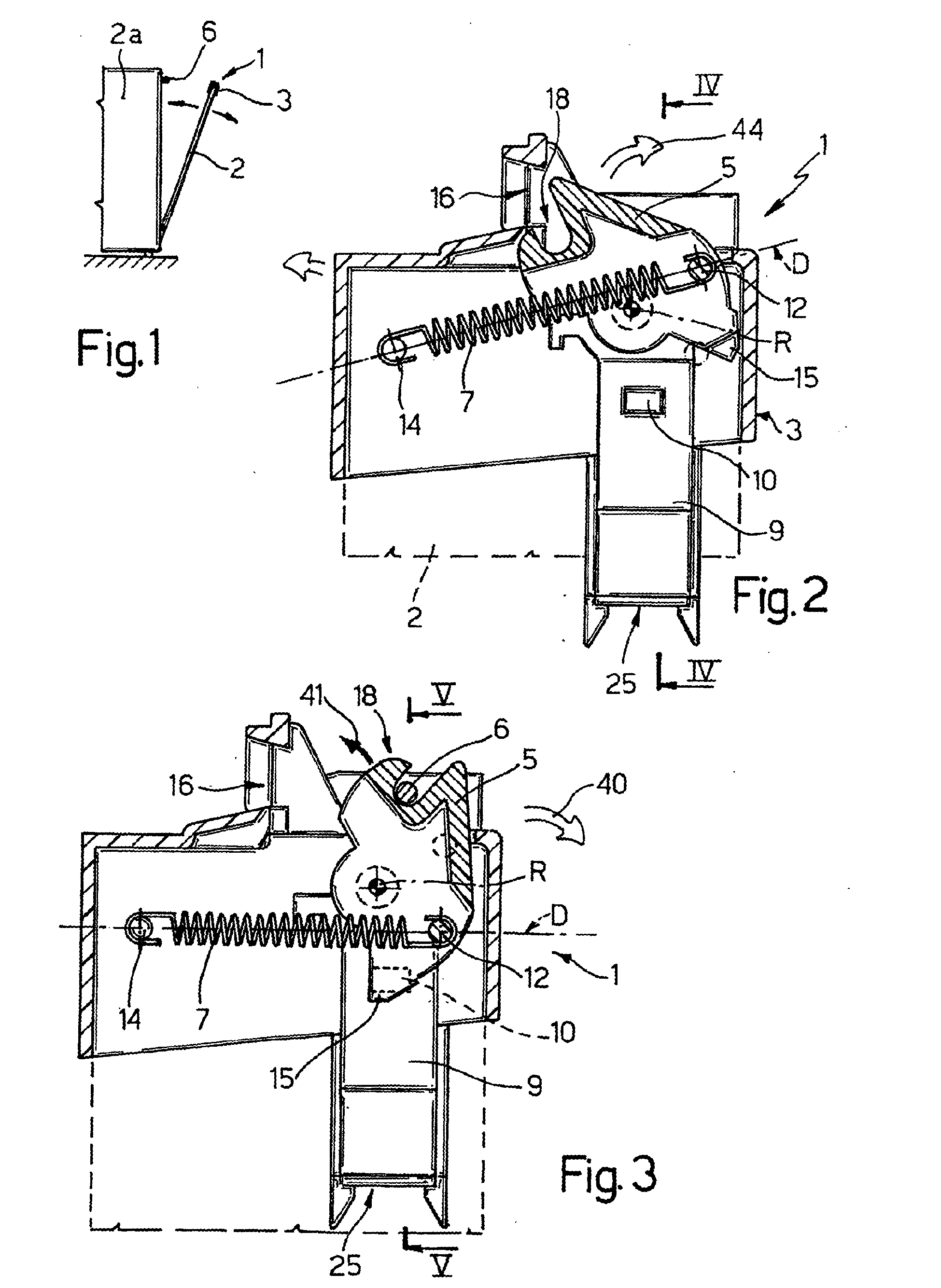
[0008] A non-limiting embodiment of the present invention will be described by way of example
with reference to the accompanying drawings, in which:
Figure 1 shows a schematic, small-scale side view of an electric household appliance
with the door open;
Figure 2 shows a schematic section of a closing device, in accordance with the invention,
for the door of the Figure 1 electric household appliance and shown in a first operating
position corresponding to the open-door condition;
Figure 3 shows a schematic section of the Figure 2 device in a second operating position
corresponding to the closed-door condition;
Figures 4 and 5 show sections along lines IV-IV and V-V of the device in the Figure
2 and 3 configurations respectively.
[0009] With reference to Figures 1 to 5, number 1 indicates as a whole a closing device
for a door 2 of an electric household appliance 2a, in particular a dishwasher. Door
2, which is known and not described or illustrated in detail for the sake of simplicity,
is fitted in known manner - in the example shown, at the top edge - with a supporting
member 3 for device 1. Supporting member 3 (hereinafter referred to simply as "support
3") includes a partly recessed seat 4 for housing a latch member 5 fitted to support
3 to rotate about an axis of rotation R (and therefore fitted integrally to door 2
via support 3 and rotating with respect to door 2) so as to cooperate with a known
catch 6 fixed to a known casing (not shown for simplicity) of the appliance.
[0010] In addition to support 3 and latch member 5, device 1 also comprises elastic contrasting
means 7 for opposing rotation of latch member 5; and a known switch device 9 for disabling
operation of appliance 2a when door 2 is open. For example, switch device 9 acts on
a circuit of the appliance (e.g. a water pump supply circuit), which is cut off, thus
stopping the appliance, when a contact element 10 is not activated (normally-closed
switch device), e.g. is not pressed inside a seat 11 (Figure 5), but projects from
the body of switch device 9 (Figures 2, 4).
[0011] According to the invention, latch member 5 comprises, in an eccentric position with
respect to its axis of rotation R, a first constraint member 12 for elastic contrasting
means 7, which is defined by a straightforward cylindrical pin projecting axially
(i.e. parallel to axis R) from a lateral face of latch member 5. According to a first
characteristic of the invention, a second constraint member 14 for elastic means 7,
also defined by a straightforward cylindrical pin, is fitted integrally to door 2
by being formed integrally in one piece with support 3.
[0012] Elastic means 7 are defined by a straightforward helical spring having an axis of
symmetry D, along which spring 7 is extensible, and which therefore constitutes the
work axis of elastic means 7. According to the invention, latch member 5 and pins
12, 14 are so arranged that axis D always connects pins 12, 14 along a straight line
lying at all times in a plane perpendicular to a plane containing the axis of rotation
R of latch member 5 - in the example shown, lying at all times in a plane parallel
to the drawing plane of figure 2, while axis R is perpendicular to the drawing plane
of figure 2.
[0013] As shown in Figures 2 and 3, latch member 5 is fitted in rotary manner to support
3 so as to selectively assume, by virtue of the action of spring 7, a first and a
second position, in which it does not activate (Figures 2 and 4) and, respectively,
does activate (Figures 3 and 5) contact element 10 of switch device 9, and in which
the work axis D of spring 7 is located on opposite sides of axis of rotation R of
latch member 5.
[0014] According to another fundamental aspect of the invention, latch member 5, as it rotates
about axis R, acts directly on contact element 10. In the example shown, latch 5 has
an eccentric, radially projecting appendix 15, which acts on and causes contact element
10 to withdraw inside seat 11 when latch member 5 is in said second position shown
in Figures 3 and 5.
[0015] In the non-limiting embodiment shown, pin 14 is carried integrally by support 3,
on the opposite side to latch member 5 and on the side of support 3 facing catch 6
in use. Seat 4 defined for latch 5 by support 3 is defined, on the side facing catch
6 in use, by a through opening 16, through which catch 6 moves in use to engage/release
a hook-shaped end 18 of latch member 5.
[0016] Latch member 5 is mounted idly on two coaxial pins 20 (Figures 4, 5) - e.g. integral
with support 3 and defining axis of rotation R - with the hook-shaped end 18 located
on the same side of work axis D in both said first and second positions.
[0017] Obviously, a dual solution to the one shown is also possible, in which pins 20 are
integral with latch member 5 and mounted idly inside coaxial seats formed in support
3.
[0018] End 18 is located substantially on the opposite side of axis R to appendix 15, and,
consequently, support 3 supports switch device 9 on the opposite side to end 18 and
axially to the side of latch member 5, i.e. shifted laterally with respect to latch
member 5, in a direction parallel to axis of rotation R of latch member 5.
[0019] Spring 7 has opposite hook-shaped ends engaging pins 12, 14, which allow the ends
of spring 7 to rotate with respect to them, and therefore spring 7 to rotate with
respect to support 3, so as to vary the orientation of axis D of spring 7 with respect
to axis R in the two positions of latch member 5 shown in Figures 2 and 3.
[0020] Support 3 being fitted, in the example shown, to the top edge of door 2, axis D of
spring 7 in said first and second position is located above and, respectively, below
axis of rotation R of latch member 5, so that use may be made of a standard switch
device 9, which is clicked inside a seat 25 formed in an appropriate position on support
3.
[0021] Device 1 operates as follows.
[0022] When the door is closed, device 1 as a whole is in a first position of stable equilibrium
shown in Figures 3 and 5, in which latch member 5 engages catch 6 and is held in position
by spring 7 fitted, always slightly preloaded, between pins 12, 14 (in the example
shown, by using a spring 7 shorter, when undeformed, than the distance in a straight
line between pins 12 and 14). Work axis D of spring 7 is located below axis of rotation
R, i.e. on the opposite side of axis R to end 18 engaging catch 6, and so keeps end
18 resting against catch 6; and appendix 15 acts on and keeps contact element 10 withdrawn
inside seat 11, so that switch device 9 enables operation of the appliance.
[0023] To open door 2, the user pulls it in the direction of arrow 40 (Figure 3) so that
it rotates with respect to the base of the appliance; as a result, catch 6 presses
against end 18 to force latch member 5 to rotate in the direction of arrow 41 about
axis R and in opposition to spring 7; and the anticlockwise rotation of latch 5 moves
eccentric pin 12 on latch member 5 away from pin 14, thus elastically stretching spring
7.
[0024] At the same time, the relative rotation between pin 14 (fixed to support 3) and latch
member 5 (fitted idly to support 3) rotates work axis D anticlockwise and upwards
towards axis R; and appendix 15 immediately releases contact element 10 which, by
means of known elastic means (not shown) inside switch device 9, is expelled from
seat 11, thus cutting off electrical supply to appliance 2a.
[0025] As door 2 is opened further, catch 6 is withdrawn from seat 4 in support 3 through
opening 16 as axis D intersects and just passes axis R; and latch member 5, with the
aid of spring 7, gets over the unstable dead-center position defined by the above
condition, and is rotated further anticlockwise by spring 7 into the Figure 2 position,
in which spring 7 has reassumed its original length, but with axis D above axis R,
so that latch 5 is retained stably in that position.
[0026] When door 2 is closed by the user, catch 6 is inserted inside seat 4 through opening
16, and pushes against end 18 to rotate latch member 5, in the direction of arrow
44 (Figure 2), back into the Figure 3 position, in the opposite sequence to that described
above, so that contact element 10 of switch device 9 is restored to the enabling position.
1. A closing device (1) for the door of an electric household appliance (2a), in particular
a dishwasher, and comprising a latch member (5), which is fitted to said door (2)
to rotate, in opposition to elastic means (7), about an axis of rotation (R), and
to cooperate with a catch (6) fixed to the electric household appliance (2a), and
activates a switch device (9) disabling operation of the electric household appliance
when the door (2) is open; wherein said latch member (5) comprises, in an eccentric
position with respect to its axis of rotation (R), a first constraint member (12)
for said elastic means (7), a second constraint member (14) for which is fitted integrally
to the door (2); said elastic means (7) being extensible along a work axis (D) connecting
said first and said second constraint member and lying at all times in a plane perpendicular
to a plane containing the axis of rotation (R) of the latch member (5); and the latch
member (5) selectively assuming, by virtue of the action of said elastic means (7),
a first and a second position, in which it does not activate and, respectively, does
activate a contact element (10) of the switch device (9), and in which said work axis
(D) of the elastic means (7) is located on opposite sides of said axis of rotation
(R) of the latch member (5); characterized in that said latch member (5) comprises an eccentric, radially projecting appendix (15) for
directly activating said contact element (10) of the switch device (9) in said second
position.
2. A device as claimed in Claim 1, characterized by also comprising a supporting member (3) fittable integrally to the door (2) and integrally
supporting said latch member (5), said elastic means (7), and said switch device;
said second constraint member (14) being fitted integrally to said supporting member
(3), on the opposite side to said latch and on the side facing said catch (6) in use.
3. A device as claimed in Claim 2, characterized in that said latch member (5) is fitted in rotary manner to said supporting member (3), and
is housed inside a seat (4) defined, on the side facing said catch (6) in use, by
a through opening (16) through which the catch (6) moves to engage/release a hook-shaped
end (18) of the latch member (5); said latch member (5) being mounted idly on two
coaxial pins (20) defining said axis of rotation (R), with said hook-shaped end (18)
located on the same side of said work axis (D) in both said first and second positions.
4. A device as claimed in Claim 3, characterized in that said supporting member (3) supports said switch device (9) on the opposite side to
said hook-shaped end (18) of the latch and axially to the side of the latch with respect
to the axis of rotation (R) of the latch member (5).
5. A device as claimed in one of the foregoing Claims, characterized in that said elastic means are defined by a helical spring (7) having said work axis (D)
as an axis of symmetry, and having hook-shaped opposite ends engaging said first (12)
and second (14) constraint member.
6. A device as claimed in Claim 5, characterized in that said first (12) and second (14) constraint member permit relative rotation between
themselves and said elastic means (7).
7. A device as claimed in Claim 6, characterized in that said first (12) and second (14) constraint member are defined by respective cylindrical
pins.
8. A device as claimed in one of Claims 2 to 7, characterized in that said supporting member (3) is fittable to a top edge of said door (2); in said first
and said second position, said work axis (D) of the elastic means (7) being located
above and, respectively below said axis of rotation (R) of the latch member (5).
9. A device as claimed in one of the foregoing Claims, characterized in that said switch device (9) disabling operation of the electric household appliance when
said contact element (10) is not activated.
1. Schließvorrichtung (1) für die Tür eines elektrischen Haushaltsgeräts (2a), insbesondere
einer Geschirrspülmaschine, mit einem Klinkenelement (5), das so an der Tür (2) angebracht
ist, dass es sich gegen elastische Mittel (7) um eine Rotationsachse (R) dreht und
mit einer Arretierung (6) zusammenwirkt, die an dem elektrischen Haushaltsgerät (2a)
befestigt ist, und das eine Schaltervorrichtung (9) aktiviert, die den Betrieb des
elektrischen Haushaltsgeräts deaktiviert, wenn die Tür (2) offen ist, wobei das Klinkenelement
(5) in einer zu seiner Rotationsachse (R) exzentrischen Position ein erstes Hemmelement
(12) für die elastischen Mittel (7) und ein zweites Hemmelement (14), das integral
an der Tür (2) angebracht ist, aufweist, wobei die elastischen Mittel (7) entlang
einer Arbeitsachse (D) gedehnt werden können, die das erste und das zweite Hemmelement
verbindet und stets in einer Ebene liegt, die senkrecht zu einer Ebene steht, die
die Rotationsachse (R) des Klinkenelements (5) enthält, und wobei das Klinkenelement
(5) dank der Wirkung der elastischen Mittel (7) gezielt eine erste und eine zweite
Position einnimmt, in der es ein Kontaktelement (10) der Schaltervorrichtung (9) nicht
aktiviert bzw. aktiviert und in der die Arbeitsachse (D) der elastischen Mittel (7)
auf gegenüberliegenden Seiten der Rotationsachse (R) des Klinkenelements (5) angeordnet
ist, dadurch gekennzeichnet, dass das Klinkenelement (5) einen exzentrischen, radial vorstehenden Fortsatz (15) aufweist,
um das Kontaktelement (10) der Schaltervorrichtung (9) in der zweiten Position direkt
zu aktivieren.
2. Vorrichtung nach Anspruch 1, dadurch gekennzeichnet, dass sie ferner ein Stützelement (3), das integral an der Tür (2) angebracht werden kann
und das Klinkenelement (5) integral stützt, die elastischen Mittel (7) und die Schaltervorrichtung
aufweist, wobei das zweite Hemmelement (14) auf der gegenüberliegenden Seite zur Klinke
und auf der im Gebrauch zur Arretierung (6) hin gerichteten Seite integral am Stützelement
(3) angebracht ist.
3. Vorrichtung nach Anspruch 2, dadurch gekennzeichnet, dass das Klinkenelement (5) drehbar am Stützelement (3) angebracht und in einem Sitz (4)
untergebracht ist, der auf im Gebrauch der zur Arretierung (6) hin gerichteten Seite
durch eine Durchgangsöffnung (16) definiert wird, durch die sich die Arretierung (6)
bewegt, um ein hakenförmiges Ende (18) des Klinkenelements (5) in Eingriff zu nehmen/freizugeben,
wobei das Klinkenelement (5) im Ruhezustand an zwei koaxialen Stiften (20) montiert
ist, die die Rotationsachse (R) definieren, wobei das hakenförmige Ende (18) sowohl
in der ersten als auch in der zweiten Position auf derselben Seite der Arbeitsachse
(D) angeordnet ist.
4. Vorrichtung nach Anspruch 3, dadurch gekennzeichnet, dass das Stützelement (3) die Schaltervorrichtung (9) auf der dem hakenförmigen Ende (18)
der Klinke gegenüberliegenden Seite und zur Seite der Klinke bezüglich der Rotationsachse
(R) des Klinkenelements (5) stützt.
5. Vorrichtung nach einem der vorhergehenden Ansprüche, dadurch gekennzeichnet, dass die elastischen Mittel durch eine Spiralfeder (7) definiert werden, deren Symmetrieachse
die Arbeitsachse (D) ist und deren hakenförmige gegenüberliegende Enden das erste
(12) und das zweite (14) Hemmelement in Eingriff nehmen.
6. Vorrichtung nach Anspruch 5, dadurch gekennzeichnet, dass das erste (12) und das zweite (14) Hemmelement die relative Drehung zwischen sich
und den elastischen Mitteln (7) gestatten.
7. Vorrichtung nach Anspruch 6, dadurch gekennzeichnet, dass das erste (12) und das zweite (14) Hemmelement durch jeweilige zylindrische Stifte
definiert werden.
8. Vorrichtung nach einem der Ansprüche 2 bis 7, dadurch gekennzeichnet, dass das Stützelement (3) an einen oberen Rand der Tür (2) angebracht werden kann, wobei
die Arbeitsachse (D) der elastischen Mittel (7) in der ersten und der zweiten Position
oberhalb bzw. unterhalb der Rotationsachse (R) des Klinkenelements (5) angeordnet
ist.
9. Vorrichtung nach einem der vorhergehenden Ansprüche, dadurch gekennzeichnet, dass die Schaltervorrichtung (9) den Betrieb des elektrischen Haushaltsgeräts deaktiviert,
wenn das Kontaktelement (10) nicht aktiviert ist.
1. Dispositif (1) de fermeture destiné à la porte d'un appareil électroménager (2a),
en particulier un lave-vaisselle, et comprenant un organe (5) de loquet qui est installé
sur ladite porte (2) de façon à tourner, en opposition à des moyens élastiques (7),
autour d'un axe (R) de rotation et à coopérer avec un fermoir (6) fixé à l'appareil
électroménager (2a), et actionne un dispositif (9) d'interrupteur désactivant le fonctionnement
de l'appareil électroménager lorsque la porte (2) est ouverte ; ledit organe (5) de
loquet comportant, en position excentrique par rapport à son axe (R) de rotation,
un premier organe (12) de contrainte pour lesdits moyens élastiques (7), pour lesquels
un deuxième organe (14) de contrainte est installé de façon intégrée sur la porte
(2) ; lesdits moyens élastiques (7) étant extensibles le long d'un axe (D) de travail
reliant ledit premier audit deuxième organe de contrainte et se situant à tout instant
dans un plan perpendiculaire à un plan contenant l'axe (R) de rotation de l'organe
(5) de loquet ; et l'organe (5) de loquet prenant sélectivement, en vertu de l'action
desdits moyens élastiques (7), une première et une deuxième position dans lesquelles
il n'active pas et, respectivement, active un élément (10) de contact du dispositif
(9) d'interrupteur, et dans lesquelles ledit axe (D) de travail des moyens élastiques
(7) est situé sur des côtés opposés dudit axe (R) de rotation de l'organe (5) de loquet
; caractérisé en ce que ledit organe (5) de loquet comporte un appendice (15) excentrique saillant radialement
destiné à activer directement ledit élément (10) de contact du dispositif (9) d'interrupteur
dans ladite deuxième position.
2. Dispositif selon la revendication 1, caractérisé en ce qu'il comporte également un organe (3) de support susceptible d'être installé de façon
intégrée sur la porte (2) et supportant de façon intégrée ledit organe (5) de loquet,
lesdits moyens élastiques (7) et ledit dispositif d'interrupteur ; ledit deuxième
organe (14) de contrainte étant installé de façon intégrée sur ledit organe (3) de
support, du côté opposé audit loquet et du côté faisant face audit fermoir (6) en
cours d'utilisation.
3. Dispositif selon la revendication 2, caractérisé en ce que ledit organe (5) de loquet est installé de façon rotative sur ledit organe (3) de
support et est logé à l'intérieur d'un siège (4) défini, du côté faisant face audit
fermoir (6) en cours d'utilisation, par une ouverture débouchante (16) à travers laquelle
le fermoir (6) se déplace pour accrocher / libérer une extrémité (18) en forme de
crochet de l'organe (5) de loquet ; ledit organe (5) de loquet étant monté librement
sur deux goupilles coaxiales (20) définissant ledit axe (R) de rotation, ladite extrémité
(18) en forme de crochet étant située du même côté dudit axe (D) de travail dans l'une
comme l'autre desdites première et deuxième positions.
4. Dispositif selon la revendication 3, caractérisé en ce que ledit organe (3) de support supporte ledit dispositif (9) d'interrupteur du côté
opposé à ladite extrémité (18) en forme de crochet du loquet et axialement au côté
du loquet par rapport à l'axe (R) de rotation de l'organe (5) de loquet.
5. Dispositif selon l'une des revendications précédentes, caractérisé en ce que lesdits moyens élastiques sont définis par un ressort hélicoïdal (7) ayant ledit
axe (D) de travail comme axe de symétrie et présentant des extrémités opposées en
forme de crochets coopérant avec lesdits premier (12) et deuxième (14) organes de
contrainte.
6. Dispositif selon la revendication 5, caractérisé en ce que lesdits premier (12) et deuxième (14) organes de contrainte permettent une rotation
relative entre eux-mêmes et lesdits moyens élastiques (7).
7. Dispositif selon la revendication 6, caractérisé en ce que lesdits premier (12) et deuxième (14) organes de contrainte sont définis par des
goupilles cylindriques respectives.
8. Dispositif selon l'une des revendications 2 à 7, caractérisé en ce que ledit organe (3) de support peut être installé sur un bord supérieur de ladite porte
(2) ; ledit axe (D) de travail des moyens élastiques (7) étant situé, dans lesdites
première et deuxième positions, respectivement au-dessus et au-dessous dudit axe (R)
de rotation de l'organe (5) de loquet.
9. Dispositif selon l'une des revendications précédentes, caractérisé en ce que ledit dispositif (9) d'interrupteur neutralise le fonctionnement de l'appareil électroménager
lorsque ledit élément (10) de contact n'est pas activé.

REFERENCES CITED IN THE DESCRIPTION
This list of references cited by the applicant is for the reader's convenience only.
It does not form part of the European patent document. Even though great care has
been taken in compiling the references, errors or omissions cannot be excluded and
the EPO disclaims all liability in this regard.
Patent documents cited in the description