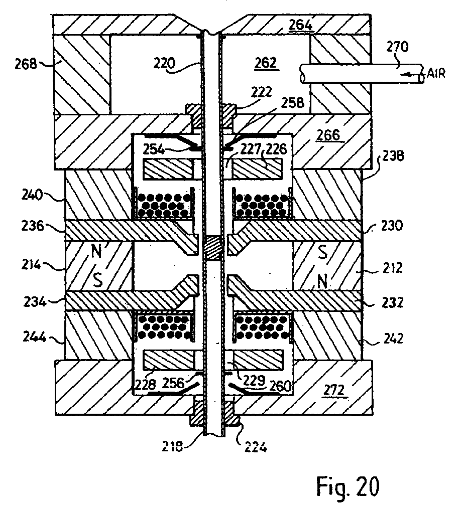
(57) A valve for controlling the flow of gas or air includes an actuator comprising a
magnetic drive device formed from permanent magnets (212, 214) generating magnetic
flux, and an armature (216) which can occupy either a first gap between one pair of
poles (230, 236) in or a second gap between another pair of poles (232, 234) with
a region of flux cancellation between the two gaps. Electromagnetic windings (246,
248) are provided to which current can be supplied which when energised produces a
magnetic flux in one direction or the other, depending on the direction of the current,
the flux from the winding increasing the flux density in the gap between one of the
poles and reducing the flux density in the gap between the other pair of poles. This
effectively shifts the flux cancellation region towards or into the gap between one
or the other of the two pairs of poles so as to produce a flux density gradient extending
from one pair of poles to the other, which will cause the armature to move into (or
remain in) the gap having the higher flux density, and continue to remain in that
air gap after the current flow ceases. An energy storing spring (258) is compressed
as the armature moves into a position between one of the pairs of poles in which the
valve is closed. The movement of the armature (216) is transmitted to a valve closure
so as to open and close the valve. A plurality of such devices may be controlled by
signals from a computer controlled signal generator to influence the flow of fluid
into the exhaust manifold of an engine.
|
|
