| (19) |
 |
|
(11) |
EP 1 506 090 B9 |
| (12) |
CORRECTED EUROPEAN PATENT SPECIFICATION |
|
Note: Bibliography reflects the latest situation |
| (15) |
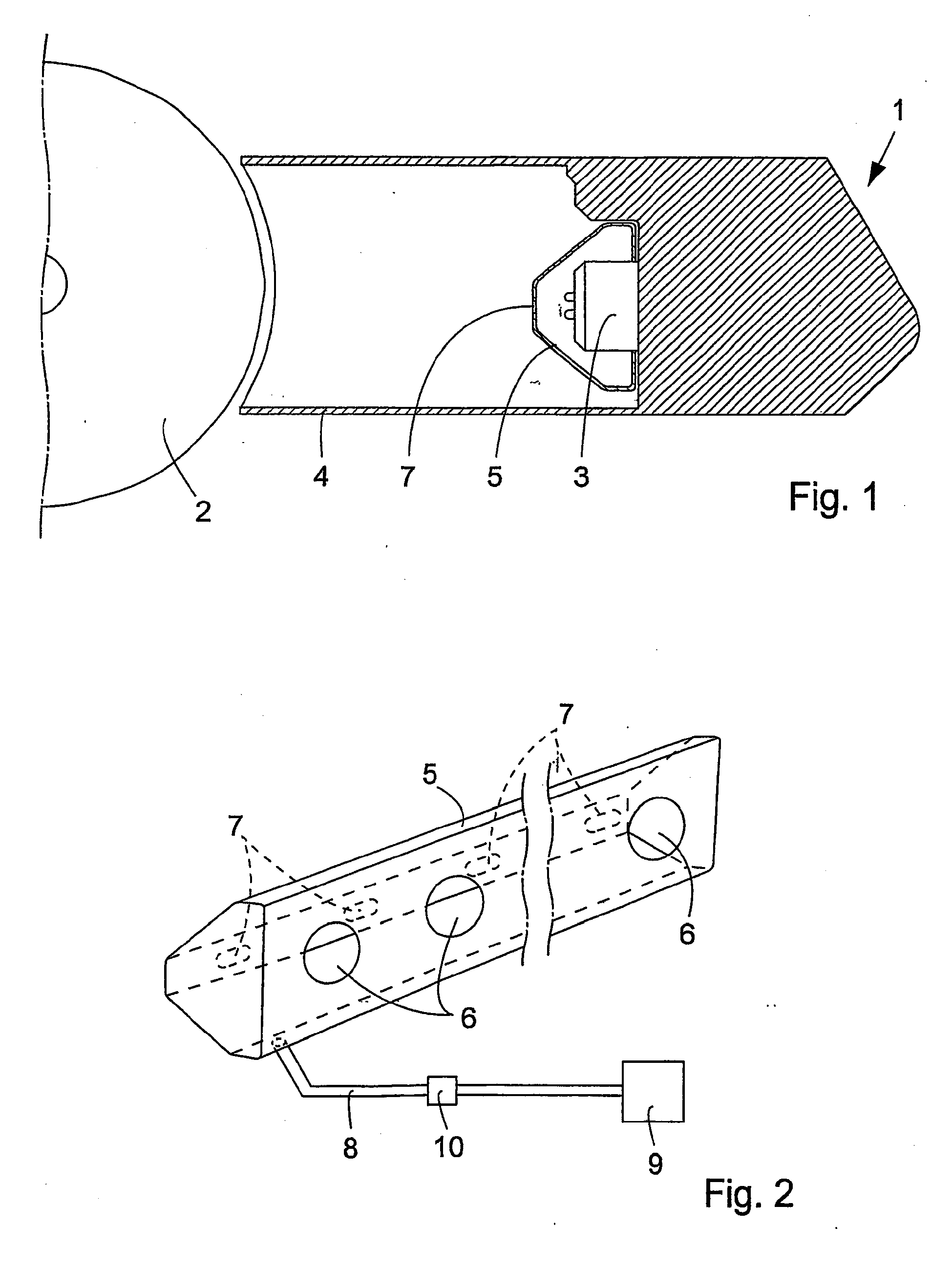
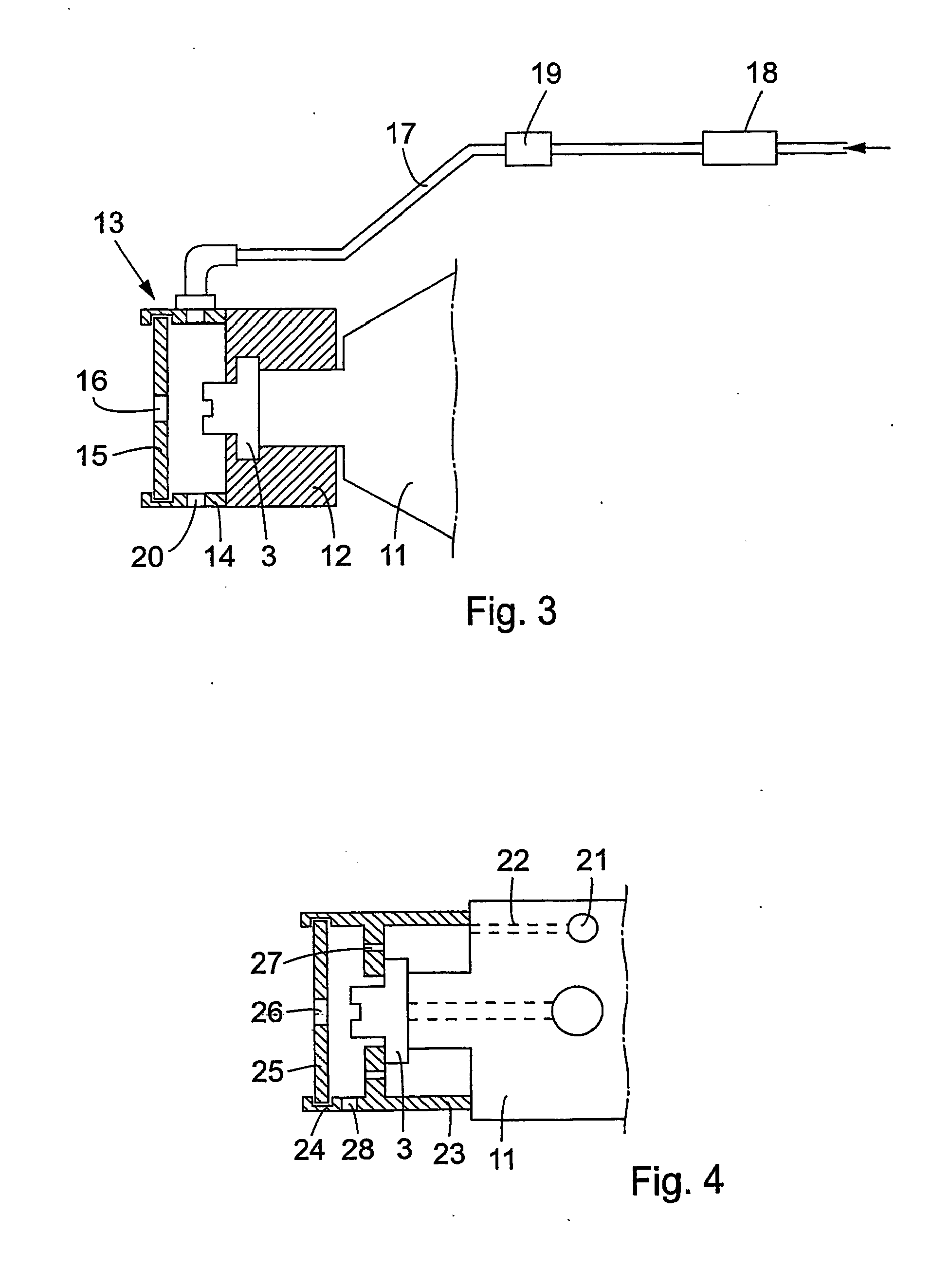
Correction information: |
|
Corrected version no 1 (W1 B1) |
|
Corrections, see
Claims EN |
| (48) |
Corrigendum issued on: |
|
04.01.2012 Bulletin 2012/01 |
| (45) |
Mention of the grant of the patent: |
|
22.06.2011 Bulletin 2011/25 |
| (22) |
Date of filing: 08.05.2003 |
|
| (51) |
International Patent Classification (IPC):
|
| (86) |
International application number: |
|
PCT/SE2003/000740 |
| (87) |
International publication number: |
|
WO 2003/097358 (27.11.2003 Gazette 2003/48) |
|
| (54) |
A METHOD AND DEVICE FOR KEEPING A NUMBER OF SPRAY NOZZLES IN A PRINTING PRESS BEAM
CLEAN
VERFAHREN UND VORRICHTUNG ZUM SAUBERHALTEN MEHRERER SPRITZDÜSEN IN EINEM DRUCKPRESSENTRÄGER
PROCEDE ET DISPOSITIF PERMETTANT DE GARDER PROPRE UN CERTAIN NOMBRE DE BUSES DE PULVERISATEUR
DANS UNE RAMPE DE PRESSE A IMPRIMER
|
| (84) |
Designated Contracting States: |
|
AT BE BG CH CY CZ DE DK EE ES FI FR GB GR HU IE IT LI LU MC NL PT RO SE SI SK TR |
| (30) |
Priority: |
17.05.2002 SE 0201483
|
| (43) |
Date of publication of application: |
|
16.02.2005 Bulletin 2005/07 |
| (73) |
Proprietor: Baldwin Jimek AB |
|
232 01 Arlöv (SE) |
|
| (72) |
Inventors: |
|
- HANSSON, Birger
S-232 51 Akarp (SE)
- ARNDT, Peter
S-23635 Höllviken (SE)
|
| (74) |
Representative: Karlsson, Leif Gunnar Börje et al |
|
Ström & Gulliksson AB
P.O. Box 4188
203 13 Malmö
203 13 Malmö (SE) |
| (56) |
References cited: :
EP-A2- 0 422 400
WO-A2-97/27052
US-A- 5 299 495
|
WO-A1-01/87603
US-A- 4 241 656
|
|
| |
|
|
|
|
| |
|
| Note: Within nine months from the publication of the mention of the grant of the European
patent, any person may give notice to the European Patent Office of opposition to
the European patent
granted. Notice of opposition shall be filed in a written reasoned statement. It shall
not be deemed to
have been filed until the opposition fee has been paid. (Art. 99(1) European Patent
Convention).
|
Technical Field
[0001] The present invention relates to a method and device for keeping a spray nozzle in
a printing press spray beam clean.
Background of the Invention
[0002] A spray beam is arranged in the proximity of a printing press roller for spraying
fountain solution thereon. This fountain solution is needed for obtaining the intended
printing function in the printing press, as is well known in the art. (Other liquids
than fountain solution could alternatively be sprayed.)
[0003] It is also well known in the art that at the high speed rotation of the different
rollers in the printing press, it is difficult to obviate the formation of a mist
of printing ink and other matters in and around the press. The printing ink also causes
certain problems in the operation of the press.
[0004] The printing ink mist causes clogging of the spray nozzles of the spray beam, so
that their intended spray function gradually deteriorates and the spray pattern of
the spray beam is changed.
[0005] A prior attempt to solve the problem with clogged spray nozzles in a special situation
is revealed in
WO 0187603, where an air stream is caused to flow towards the printing press roller in the spray
casing covering the area between the spray beam and the roller.
[0006] A method and a device as defined in the preamble of claims 1 and 2, respectively,
is disclosed in
US-A-4241656.
The Invention
[0007] According to the invention the above mentioned problem can be solved in that air
with a certain overpressure is supplied to a cover surrounding the spray nozzle, the
spray cone from the spray nozzle leaving the cover undisturbed through a slot therein.
[0008] A device for carrying out this method is characterized by a cover, which surrounds
the spray nozzle and has a slot for the spray cone from the spray nozzle to leave
the cover undisturbed, and by means for supplying air with a certain overpressure
to the cover.
[0009] Favourable embodiments appear from the dependent claims.
The Drawings
[0010] The invention will be described in further detail below under reference to the accompanying
drawings, in which
Fig 1 is a diagrammatic cross section through a spray beam provided with a first device
not according to the invention,
Fig 2 is a perspective view of the first device of Fig 1,
Fig 3 is a cross section through a spray nozzle with a device according to the invention,
and
Fig 4 is a cross section through a spray nozzle with a further device according to
the invention.
Detailed Description of Embodiments
[0011] A so called spray beam 1 is shown in a very diagrammatic cross section in Fig 1.
The purpose of such a spray beam is to spray fountain solution on a rotating printing
press roller 2. Fountain solution is sprayed from a number of spray nozzles 3, placed
in a row in the spray beam, through a spray casing 4 constituting the forward portion
of the spray beam 1.
[0012] The purpose of the spray casing 4 is to keep the fountain solution properly confined
but also to prevent printing ink mist and other contaminants from reaching the spray
nozzles 3.
[0013] However, in spite of these measures it is a known problem that the spray nozzles
3 may be clogged after a certain operation time and may fail to function properly,
leading among other things to an impaired distribution of fountain solution over the
width of the roller 2 to be sprayed.
[0014] Measures accordingly need to be taken to ensure that the nozzles 3 are kept clean.
[0015] Figs 1 and 2 show a device for this purpose not representing the invention.
[0016] An elongated, generally closed cover 5 is mounted over all the spray nozzles 3 on
the spray beam 1. The cover 5 can be formed of stainless steel plate or the like,
but the choice of material is of no significance. The cover 5 is provided in its back
wall with openings 6 for the spray nozzles 3 and in its front wall with oblong holes
or slots 7 enabling the spray cones from the spray nozzles 3 to leave the cover 5
undisturbed.
[0017] Clean air with a certain overpressure is supplied to the interior of the cover 5
by means of an air conduit 8 from a main valve with a pressure regulator 9 and a throttle
valve 10 for controlling the air flow. In order to obtain the desired result, several
air conduits 8 from the throttle valve 10 may be evenly distributed over the length
of the cover 5. It may possibly be desired to provide the bottom of the cover 5 with
a number of drainage holes (not shown).
[0018] The air will create a certain overpressure in the cover 5 and escape through its
slots 7 without disturbing the spray cones from the spray nozzles 3. In this way contaminants
are effectively prevented from reaching the spray nozzles 3, which accordingly will
be kept clean for an extended period of time .
[0019] A first embodiment of the invention is shown in Fig 3. Each spray nozzle 3 is connected
to its spray valve 11 in the spray beam 1 by means of a cap 12, which may be made
of a plastic material.
[0020] A cover 13 is individually provided for each spray nozzle 3. In the present case
it has the form of a short sleeve 14, connected in a way not shown (but possibly by
means of a bayonet joint) to the cap 12 and possibly made of a plastic material, and
an end plate 15 inserted in a circumferential groove in the end of the sleeve 14.
The end plate 15 has an oblong slot 16 for the spray cone from the spray nozzle 3
to pass through.
[0021] An air conduit 17 for the supply of clean air with a certain overpressure is connected
to the sleeve 14. The air conduit 17 can be provided with a main valve with a pressure
regulator 18 and a throttle valve 19 for controlling the air flow. The members 18
and 19 may be common for several air conduits 17 to several spray nozzles 3. Means
may be provided in the cover 13 for evenly distributing the air inside the cover.
[0022] The sleeve 14 may be provided with a drainage hole 20 in its bottom portion.
[0023] The provision of a separate end plate 15 is based on manufacturing considerations.
[0024] The embodiment according to Fig 3 may be especially suitable for existing spray beams,
as the cover arrangement for each spray nozzle may be mounted without modifications
to the existing device.
[0025] The embodiment according to Fig 4 may be more suitable for new arrangements, where
the design freedom is greater. In this case the spray valve 8 is provided with a separate
main air conduit 21 extending from spray valve to spray valve in the spray beam. An
air bore 22 extends forward in the valve from the air conduit 21. The diameter of
the bore 22 is such that a throttling for the air is accomplished in order to control
the air flow.
[0026] The cap device 23 for connecting the spray nozzle 3 with the spray valve 11 is integrated
with the cover arrangement 24, possibly having an end plate 25 provided with a slot
26.
[0027] A partition wall bearing against the spray nozzle 3 has a number of through holes
27 for supplying air into the cover 24, which may be provided with a drainage hole
28.
[0028] It is believed that favourable results can be obtained with an air pressure in the
region of 1.0- 1.5 bar, probably 1.2 bar, and an air flow of for example up to 1 litre/min
or more, but these figures are in no way meant to be limiting for the scope of the
invention.
1. A method for keeping a number of spray nozzles (3) in a printing press spray beam
(1) clean, wherein air with a certain flow rate is supplied to separate covers (13;
24), each separate cover surrounding a single spray nozzle (3) characterized in that each separate cover has an opening (16; 26) for a spray cone from the spray nozzle
(3), wherein the air flow rate is controlled by means of a throttling device (19;
22) connected to each separate cover (13; 24) such that the air flow is low enough
not to disturb the spray from the nozzle (3).
2. A device for keeping a number of spray nozzles (3) in a printing press spray beam
(1) clean, each spray nozzle (3) being surrounded by a separate cover (13; 24) characterized in that each separate cover comprises an opening (16; 26) for a spray cone from the spray
nozzle (3), each cover (13; 24) is connected to air flow control means (17-19; 21,
22, 27) comprising a throttling device (19; 22) that restricts the air flow enough
to leave the spray cone undisturbed, and wherein the opening is designed not to disturb
the spray from the nozzle.
3. The device according to claim 2, wherein the opening (16; 26) in the cover (13; 24)
has the form of a slot.
4. The device according to claims 2 and 3, wherein each cover (13; 24) is provided with
a drainage hole (20; 28).
5. The device according to any of the preceding claims 2-4, wherein an external air conduit
(17) is connected to the covers (13).
6. The device according to any of the preceding claims 2-5, wherein a spray valve (11)
for the spray nozzle (3) is provided with an internal air conduit (21) and an air
bore (22) connected to the cover (24).
7. The device according to claim 6, wherein the air bore (22) has such a diameter that
a throttling effect is obtained.
8. The device according to any of the preceding claims 2-7, wherein each cover (13; 24)
is formed as a short sleeve (14; 24) connected to a spray valve cap (12; 23) and having
an end plate (15; 25) attached to its end remote from the spray nozzle (3), the end
plate being provided with the opening (16; 26).
1. Verfahren zum Sauberhalten einer Anzahl von Spritzdüsen (3) in einem Druckerpressensprühträger
(1), wobei Luft mit einer bestimmten Durchflussrate zu separaten Abdeckungen (13;
24) zugeführt wird, und jede separate Abdeckung eine einzelne Spritzdüse (3) umgibt,
dadurch gekennzeichnet, dass jede separate Abdeckung eine Öffnung (16; 26) für einen Spritzkegel der Spritzdüse
(3) hat, wobei die Luftdurchflussrate mittels einer Drosselvorrichtung (19; 22) gesteuert
wird, die mit jeder separaten Abdeckung (13; 24) so verbunden ist, dass der Luftstrom
so niedrig ist, dass er das Spritzen der Düse (3) nicht stört.
2. Vorrichtung zum Sauberhalten einer Anzahl von Spritzdüsen (3) in einem Druckpressensprühträger
(1), wobei jede Spritzdüse (3) von einer separaten Abdeckung (13; 24) umgeben ist,
dadurch gekennzeichnet, dass jede separate Abdeckung eine Öffnung (16; 26) für einen Spritzkegel der Spritzdüse
(3) umfasst, jede Abdeckung (13; 24) mit einem Mittel (17-19; 21, 22, 27) zum Steuern
des Luftstroms umfassend eine Drosselvorrichtung (19; 22), welche den Luftstrom stark
genug beschränkt, um den Spritzkegel ungestört zu lassen, verbunden ist, und wobei
die Öffnung ausgebildet ist, um das Spritzen der Düse nicht zu stören.
3. Vorrichtung nach Anspruch 2, wobei die Öffnung (16; 26) in der Abdeckung (13; 24)
die Form eines Schlitzes hat.
4. Vorrichtung nach Anspruch 2 oder 3, wobei jede Abdeckung (13; 24) mit einem Ablaufloch
(20; 28) ausgestattet ist.
5. Vorrichtung nach einem der voranstehenden Ansprüche 2 bis 4, wobei eine externe Luftleitung
(17) mit den Abdeckungen (13) verbunden ist.
6. Vorrichtung nach einem der voranstehenden Ansprüche 2 bis 5, wobei ein Spritzventil
(11) für die Spritzdüse (3) mit einer internen Luftleitung (21) und einer mit der
Abdeckung (24) verbundenen Luftbohrung (22) versehen ist.
7. Vorrichtung nach Anspruch 6, wobei die Luftbohrung (22) einen solchen Durchmesser
hat, dass ein Drosseleffekt erreicht wird.
8. Vorrichtung nach einem der voranstehenden Ansprüche 2 bis 7, wobei jede Abdeckung
(13; 24) als eine kurze Hülse (14; 24) gebildet ist, welche mit einer Spritzventilkappe
(12; 23) verbunden ist und eine Endplatte (15; 25) an ihrem von der Spritzdüse (3)
entfernten Ende angebracht hat, wobei die Endplatte mit der Öffnung (16; 26) versehen
ist.
1. Procédé pour garder propre un certain nombre de buses de pulvérisation (3) dans une
rampe de pulvérisation (1) de presse à imprimer, dans lequel des couvercles séparés
(13 ; 24) sont alimentés en air avec un certain débit, chaque couvercle séparé entourant
une buse de pulvérisation unique (3), caractérisé en ce que chaque couvercle séparé a une ouverture (16 ; 26) pour un cône de pulvérisation de
la buse de pulvérisation (3), dans lequel le débit d'air est contrôlé au moyen d'un
dispositif d'étranglement (19 ; 22) raccordé à chaque couvercle séparé (13 ; 24) de
sorte que l'écoulement d'air est assez lent pour ne pas perturber la pulvérisation
à partir de la buse (3).
2. Dispositif pour garder propre un certain nombre de buses de pulvérisation (3) dans
une rampe de pulvérisation (1) de presse à imprimer, chaque buse de pulvérisation
(3) étant entourée par un couvercle séparé (13 ; 24), caractérisé en ce que chaque couvercle séparé comprend une ouverture (16 ; 26) pour un cône de pulvérisation
de la buse de pulvérisation (3), chaque couvercle (13 ; 24) est raccordé à des moyens
de contrôle de débit d'air (17-19 ; 21, 22, 27) comprenant un dispositif d'étranglement
(19 ; 22) qui limite suffisamment le débit d'air pour ne pas perturber le cône de
pulvérisation, et dans lequel l'ouverture est conçue afin de ne pas perturber la pulvérisation
de la buse.
3. Dispositif selon la revendication 2, dans lequel l'ouverture (16 ; 26) dans le couvercle
(13 ; 24) a la forme d'une fente.
4. Dispositif selon les revendications 2 et 3, dans lequel chaque couvercle (13 ; 24)
est prévu avec un trou d'évacuation (20 ; 28).
5. Dispositif selon l'une quelconque des revendications 2 à 4, dans lequel un conduit
d'air externe (17) est raccordé aux couvercles (13).
6. Dispositif selon l'une quelconque des revendications 2 à 5 précédentes, dans lequel
une soupape de pulvérisation (11) pour la buse de pulvérisation (3) est prévue avec
un conduit d'air interne (21) et un alésage d'air (22) raccordé au couvercle (24).
7. Dispositif selon la revendication 6, dans lequel l'alésage d'air (22) a un diamètre
tel que l'on obtient un effet d'étranglement.
8. Dispositif selon l'une quelconque des revendications 2 à 7 précédentes, dans lequel
chaque couvercle (13 ; 24) est formé comme un manchon court (14 ; 24) raccordé à un
capuchon de soupape de pulvérisation (12 ; 23) et ayant une plaque d'extrémité (15
; 25) fixée à son extrémité à distance de la buse de pulvérisation (3), la plaque
d'extrémité étant dotée de l'ouverture (16 ; 26).
REFERENCES CITED IN THE DESCRIPTION
This list of references cited by the applicant is for the reader's convenience only.
It does not form part of the European patent document. Even though great care has
been taken in compiling the references, errors or omissions cannot be excluded and
the EPO disclaims all liability in this regard.
Patent documents cited in the description