| (19) |
 |
|
(11) |
EP 1 799 405 B1 |
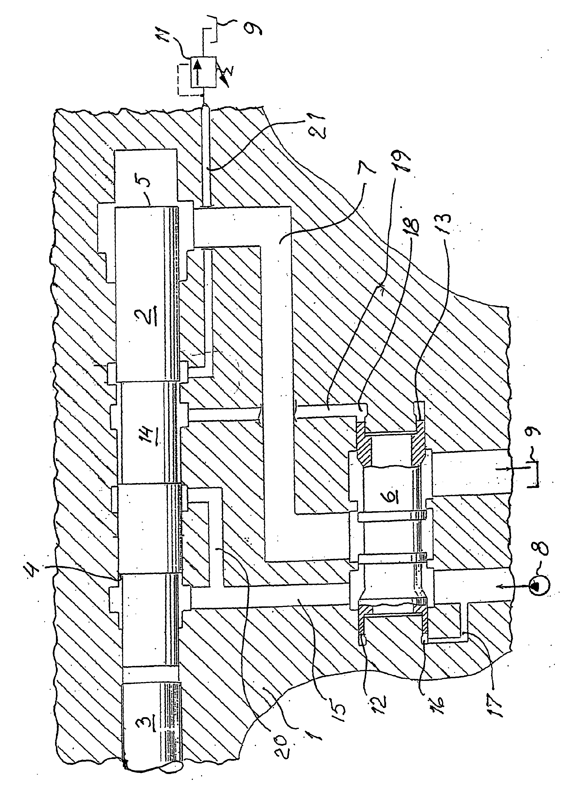
| (12) |
EUROPEAN PATENT SPECIFICATION |
| (45) |
Mention of the grant of the patent: |
|
20.03.2013 Bulletin 2013/12 |
| (22) |
Date of filing: 28.09.2005 |
|
| (51) |
International Patent Classification (IPC):
|
| (86) |
International application number: |
|
PCT/SE2005/001425 |
| (87) |
International publication number: |
|
WO 2006/041376 (20.04.2006 Gazette 2006/16) |
|
| (54) |
PERCUSSION DEVICE
SCHLAGVORRICHTUNG
DISPOSITIF À PERCUSSION
|
| (84) |
Designated Contracting States: |
|
AT BE BG CH CY CZ DE DK EE ES FI FR GB GR HU IE IS IT LI LT LU LV MC NL PL PT RO SE
SI SK TR |
| (30) |
Priority: |
14.10.2004 SE 0402482
|
| (43) |
Date of publication of application: |
|
27.06.2007 Bulletin 2007/26 |
| (73) |
Proprietor: Atlas Copco Rock Drills AB |
|
SE-701 91 Orebro (SE) |
|
| (72) |
Inventors: |
|
- ANDERSSON, Kurt
S-135 54 Tyresö (SE)
- RODERT, Jörgen
S-132 41 Saltsjö-Boo (SE)
|
| (56) |
References cited: :
WO-A1-2004/073931
US-A- 3 774 502
US-A- 4 899 836
US-A- 5 979 291
|
US-A- 3 322 038
US-A- 3 965 799
US-A- 5 372 196
|
|
| |
|
|
|
|
| |
|
| Note: Within nine months from the publication of the mention of the grant of the European
patent, any person may give notice to the European Patent Office of opposition to
the European patent
granted. Notice of opposition shall be filed in a written reasoned statement. It shall
not be deemed to
have been filed until the opposition fee has been paid. (Art. 99(1) European Patent
Convention).
|
[0001] The present invention relates to a percussion device of the type that is included
in rock drilling machines.
[0002] In a previously known percussion device of this kind, see
US 5372196, it has been proved to be difficult to obtain sufficiently fast valve change-over
in order to work at the high frequencies that are desired in modern high performance
drilling. An essential explanation thereto is that an important portion of the liquid
which is located in front of the valve body at the return of the valve body continues
because of inertia. Because of this a refill must take place in order to build up
the pressure before the valve body starts to move in the opposite direction.
[0003] US 3322038 discloses a percussion device having the features of the preamble of claim 1.
[0004] The present invention as defined in the following claim, aims at creating a percussion
device with fast valve change over which is suitable for high performance drilling.
[0005] An embodiment of the invention is described below with reference to the annexed drawing
which schematically shows a section through a percussion device according to the invention.
[0006] The percussion device shown on the drawing includes a machine housing 1, wherein
a percussion piston 2 is reciprocatingly movable in order to subject a tool 3 to impacts.
The tool is as usual provided with a here not shown drill bit. The percussion piston
is provided with a first driving surface 4 which in the shown example is continuously
pressurized by a pressure source 8 over a channel 15. The percussion piston is further
provided with a second driving surface 5 which in the shown example is comprised of
the rear surface of the percussion piston. The driving surface 5 is alternately connected
to the pressure source 8 or to the low pressure of the tank 9 over channel 7 and a
valve body 6 which is movable forwards and backwards in the machine housing. As an
alternative the valve body could connect both driving surfaces alternately to the
pressure source or low pressure. In the shown example, the pressurizing of the first
driving surface 4 drives the percussion piston to the right in the figure. Since the
area of the second driving surface 5 is essentially larger than the area of the first
driving surface 4, pressurizing of the driving surface 5 results in that the percussion
piston is driven to the left in the figure, against the effect of the pressure on
the driving surface 4. The valve body 6 is constructed as a tubular slide with a first
end surface 12 which is subjected for the pressure in a first chamber 16. The chamber
16 is over the channel 17 connected to the pressure source 8. The valve body 6 is
further provided with a second end surface 13 which is subjected to the pressure in
a second chamber 18. The chamber 18 is over the channel 19 connected to the cylinder
bore of the percussion piston 2. The pressure in the channel 19 is controlled by the
percussion piston 2 which is provided with a portion 14 having a reduced diameter.
When the percussion piston 2 is positioned somewhat to the left of the position in
the figure, the channel 19 is in connection with the pressure source 8 over the channels
15 and 20. The valve body 6 is then pressed to the left in the figure. When the percussion
piston 2 reaches the position shown in the figure, the connection of the channel 19
with the pressure source 8 has been broken and a connection with the channel 21 started
to open. In the channel 21 there is positioned a constant pressure valve 11. Its function
is to give a constant fall off pressure independent of the flow through the valve.
It is thus a valve device for creating a counter-pressure. Hereby the amount of liquid
leaving the channel 19 when the valve body 6 changes direction in its right position
in the figure is essentially reduced, whereby the change-over goes essentially faster.
1. Percussion device for rock drilling machines including a machine housing (1), a forwards
and backwards movable percussion piston (2) in a cylinder bore in the machine housing
(1), and a reciprocating movable valve body (6) in the machine housing, said percussion
piston (2) being adapted to subject a tool (3) to impacts, and said percussion piston
including a first (4) and a second (5) driving surface intended to be subjected to
pressure in order to drive the percussion piston forwards and backwards, said valve
body (6) including a first end surface (12) and a second end surface (13), wherein
the pressurizing of the first end surface (12) tends to drive the valve body in a
first direction and pressurizing of the second end surface (13) tends to drive the
valve body in a second direction, whereby the valve body (6), in the machine housing,
is arranged to connect at least the second (5) of the driving surfaces alternately
to a pressure source (8) or to a low pressure tank(9), and the second end surface
(13) of the valve body (6), is alternately connected, over a first channel (20), to
the pressure source (8) or, over a second channel (21), to the low pressure tank(9),
dependent on the position of the percussion piston (2), characterized in that a constant pressure valve device (11) is positioned in said second channel (21) for
creating a counter pressure to the low pressure tank (9) for fast valve body (6) change
over.
1. Schlagvorrichtung für Gesteinsbohrmaschinen mit einem Maschinengehäuse (1), einem
vorwärts und rückwärts bewegbaren Schlagkolben (2) in einer Zylinderbohrung im Maschinengehäuse
(1) und einem hin und her bewegbaren Ventilkörper (6) im Maschinengehäuse, wobei der
Schlagkolben (2) geeignet ist, ein Werkzeug (3) Schlägen auszusetzen und der Schlagkolben
eine erste (4) und eine zweite (5) Antriebsfläche für die Druckbeaufschlagung enthält,
um den Schlagkolben vorwärts und rückwärts zu bewegen, wobei der Ventilkörper (6)
eine erste Stirnfläche (12) und eine zweite Stirnfläche (13) enthält, wobei die Druckbeaufschlagung
der ersten Stirnfläche (12) für Bewegung des Ventilkörpers in einer ersten Richtung
sorgt und die Druckbeaufschlagung der zweiten Stirnfläche (13) für Bewegung des Ventilkörpers
in einer zweiten Richtung sorgt, wobei der Ventilkörper (6) im Maschinengehäuse angeordnet
ist, um zumindest die zweite (5) der Antriebsflächen abwechselnd mit einer Druckquelle
(8) oder mit einem Unterdruckbehälter (9) zu verbinden, und die zweite Stirnfläche
(13) des Ventilskörpers (6), abhängig von der Position des Schlagkolbens (2), abwechselnd
über einen ersten Kanal (20) mit der Druckquelle (8) oder über einen zweiten Kanal
(21) mit dem Unterdruckbehälter (9) verbunden ist, dadurch gekennzeichnet, dass eine Druckhalteventilvorrichtung (11) im zweiten Kanal (21) angeordnet ist, um für
einen raschen Wechsel des Ventilkörpers (6) einen Gegendruck zum Unterdruckbehälter
(9) zu erzeugen.
1. Dispositif de percussion pour le forage de roches comprenant un corps de machine (1),
un piston de percussion mobile en avant et en arrière (2) dans un alésage du corps
de machine (1), et un corps de vanne mobile alternativement (6) dans le corps de machine,
ledit piston de percussion (2) étant adapté pour soumettre un outil (3) à des impacts,
et ledit piston de percussion incluant une première (4) et une deuxième surface (5)
d'entraînement conçues pour être soumises à la pression afin d'entraîner le piston
de percussion vers l'avant et vers l'arrière, ledit corps de vanne (&) incluant une
première surface d'extrémité (12) et une deuxième surface d'extrémité (13), où l'application
d'une pression à la première surface d'extrémité (12) tend à entraîner le corps de
vanne dans une première direction et l'application d'une pression à la deuxième surface
d'extrémité (13) tend à entraîner le corps de vanne dans une deuxième direction, dans
lequel le corps de vanne (6), dans le corps de machine, est disposé pour connecter
au moins la deuxième (5) des surfaces motrices alternativement à une source de pression
(8) ou à un réservoir basse pression (9), et la deuxième surface d'extrémité (13)
du corps de vanne (6), est alternativement connectée, par un premier canal (20), à
la source de pression (8) ou, par un deuxième canal (21), au réservoir basse pression
(9), selon la position du piston de percussion (2), caractérisé en ce qu'un dispositif de soupape de pression constante (11) est placé dans ledit deuxième
canal (21) pour créer une contre-pression dans le réservoir basse pression (9) pour
un changement d'état rapide du corps de la vanne (6).
REFERENCES CITED IN THE DESCRIPTION
This list of references cited by the applicant is for the reader's convenience only.
It does not form part of the European patent document. Even though great care has
been taken in compiling the references, errors or omissions cannot be excluded and
the EPO disclaims all liability in this regard.
Patent documents cited in the description