|
(11) | EP 2 200 207 A1 |

| (12) | EUROPEAN PATENT APPLICATION |
|
|
|
|
|||||||||||||||||||
| (54) | Error correction scheme in a hearing system wireless network |
| (57) The present invention relates to a hearing instrument wireless network for wireless
interconnection of hearing instruments with each other, and wireless interconnection
of hearing instruments with other devices, such as remote controllers, fitting instruments,
mobile phones, media players, headsets, door bells, alarm systems, broadcast systems,
such as tele coil replacement, etc, etc, wherein transmission of data is performed
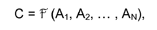
in data packages A1, A2, ... , AN, C, wherein each of the data packages A1, A2, ... , AN, C is transmitted in an individual frequency channel, and wherein data
package C is a function of A1, A2, ... , AN: C = (A1, A2, ... , AN), and wherein, in case of detection of an error in data package AE during data reception, where AE is one of the received data packages A1, A2, ... , AN: the data package AE is recovered by: AE = (A1, A2, ... , C, ... , AN), wherein A1, A2, ... , C, ... , AN indicates that data package C replaces defective data package
AE in the list of arguments of function R.
|
[0001] The present invention relates to a hearing instrument wireless network for wireless interconnection of hearing instruments with each other, and wireless interconnection of hearing instruments with other devices, such as remote controllers, fitting instruments, mobile phones, media players, headsets, door bells, alarm systems, broadcast systems, such as tele coil replacement, etc, etc.
[0002] WO 2004/110099 discloses a hearing aid wireless network with a communication protocol that is simple thereby requiring a small amount of code and power consumption during operation. Further, the acquisition time is low, and the latency is low.
[0003] Numerous schemes of correcting data transmission errors in noisy communication channels are known in the art. Typically, a number of bits is added to data bits in a data package according to a certain encoding scheme making it possible to detect a certain number of bit errors caused by noise in the communication channel and also correct a certain, typically smaller, number of bit errors in a de-coder. Some schemes include re-transmission of data packages. Error correction schemes increase the time needed for transmission and reception of a certain number of data bits, and wireless communication circuitry requires significant amounts of power during reception and transmission of data.
[0004] Typically, in a hearing instrument, such as a hearing aid, only a limited amount of power is available from the power supply. For example, in a hearing aid, power is typically supplied from a conventional ZnO2 battery.
[0005] Thus, in a hearing system, it is desirable to minimize the time transmitters and receivers are actively performing transmission and reception, respectively. For example, it is desirable to minimize re-transmission of data packets.
[0006] Accordingly, a hearing system is provided, comprising a hearing instrument having a receiver for wireless data communication between the hearing instrument and another device in a wireless network. The hearing instrument may further have a communication controller that is configured for controlling the wireless data communication.
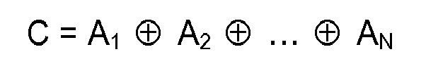
[0007] In accordance with the present error correction scheme, a data package D containing B bits to be transmitted, is divided into a number N of data packages A1, A2, ... , AN, Preferably, but not necessarily, data packages A1, A2, ... , AN contain identical number of bits
In order to be able to detect and correct possible bit errors in one data package AI a further data package C is formed as a function of A1, A2, ... , AN:
[0008] Then, the data packages A1, A2, ... , AN, and C are transmitted wirelessly from a transmitting device in the wireless network.
[0009] In the hearing instrument or another device connected to the wireless network and for which the transmitted data packages are intended, the data receiver is activated, e.g. turned on, to perform data reception of data packages A1, A2, ... , AN, and C. The data receiver also performs error detection and, in case of detection of error(s) in one of the data packages A1, A2, ... , AN, namely AE, data recovery is performed based on the remaining data packages A1, A2, ... , AN, and C in accordance with:
wherein A1, A2, ... , C, ... , AN indicates that data package C replaces the defective data package AE in the list of arguments of function
AE may be any one of the data packages A1, A2, ... , AN.
[0010] Thus, the function
is used to calculate redundant data information inserted into the transmitted data stream in accordance with specific algebraic relations so that the received data stream, in the event that errors have been introduced during data transmission, can be corrected using the corresponding reversed specific algebraic relations constituting the function
[0011] It should be noted that division of original data package D with B bits into a number of data packages A1, A2, ... , AN, e.g. of the same size
leads to the advantage that only one extra package C with a small number of bits, e.g.
needs to be transmitted and received. Thus, the time the receiver needs to be activated in order to be able to perform data recovery is only increased by
[0012] Preferably, the communication controller is configured to control the receiver in such a way that reception of data package C takes place solely in case of detection of error(s) in data packages A1, A2, ... , AN. Hereby further power consumption by the receiver is saved when no error(s) is detected, since reception of data package C is not performed in case of error free data transmission of A1, A2, ... , AN.
[0013] An error in the received data stream may be detected using e.g. parity bits, Hamming code, checksum, cyclic redundancy check, etc.
[0014] Accordingly, a hearing system is provided comprising a hearing instrument having a receiver for wireless data communication between the hearing instrument and another device in a wireless network, and a communication controller that is configured for controlling the receiver for data reception of data packages A1, A2, ... , AN, and C. The receiver is further configured for performing error detection, and in case of detection of an error in one of the data packages A1, A2, ... , C, ... , AN, namely AE, for recovering the data package AE in accordance with: AE =
(A1, A2, ... , C, ... , AN), wherein A1, A2, ... , C, ... , AN indicates that data package C replaces defective data package AE in the list of arguments of function
[0015] Thus, in a device connected in the wireless network, a communication controller of the device may be configured for always performing data reception of data package C in addition to data reception of data packages A1, A2, ... , AN whether an error has been detected or not, for example in a device with plenty of power available. Still, data recovery may be performed solely in response to detection of an error in one, namely AE, of the received data packages A1, A2, ... , AN.
[0016] However, in a device with limited amount of power available, data reception of data package C may be performed solely in response to detection of an error in one of the received data packages A1, A2, ... , AN.
[0017] According to the present error correction scheme, the transmitting device always transmits the extra data package C for possible subsequent error correction; however, typically the transmitting device is a device with a large power supply, such as a remote controller, a fitting instrument, a mobile phone, a media players a headset, a door bell, an alarm system, a broadcast system, etc. The transmitting device may also be a hearing instrument.
[0020] For example, N may be equal to 2 so that data package D containing B bits to be transmitted is divided into 2 data packages A1 and A2, each of which contains
its. In order to be able to detect and correct possible bit errors in a data package, a further data package C is formed as a function of A1 and A2:
[0021] Then, the data packages A1 and A2, and C are transmitted wirelessly from a transmitting device in the wireless network.
[0022] In the hearing instrument or another device connected to the wireless network and for which the transmitted data packages are intended, the data receiver is activated, e.g. turned on, to perform data reception of data packages A1 and A2 and C. The data receiver also performs error detection and, in case of detection of error(s) in A1 or A2, data recovery is performed based on:
[0023] It should be noted that division of original data package D with B bits into two data packages A1 and A2 of the same size
bits, leads to the advantage that only one extra package C with
bits needs to be transmitted and received. Thus, the time the receiver needs to be activated in order to be able to perform data recovery is only increased by
[0024] Preferably, the communication controller is configured to control the receiver in such a way that reception of data package C takes place solely in case of detection of error(s) in data package A1 or A2. Hereby further power consumption by the receiver is saved when no error(s) is detected, since reception of data package C is not performed in case of error free data transmission of A1 and A2.
[0025] The limited power supply requirement of the provided error correction scheme makes it suitable for incorporation in a hearing instrument with limited power supply capabilities.
[0026] The hearing instrument may be a hearing aid, a tinnitus relieving device, a tinnitus therapy device, a noise suppression device, etc., or any combination of two or more of such devices.
[0027] The receiver and transmitter of the hearing instrument may be comprised in a radio chip, such as the Nordic Semiconductor radio chip "nRF24I01". A radio chip of this type draws significant amounts of current both when it transmits and receives. A conventional ZnO2 battery is only capable of supplying the required amount of current for a limited time period, typically 1 millisecond. Continued supply of the required amount of current leads to a lowered supply voltage, below which digital signal processing circuitry will stop operating properly. Further, the ZnO2 battery will require time to recover after having supplied current to the radio chip during communication. Typically, the radio chip duty cycle, i.e. the percentage of radio turn-on time with respect to the sum of the radio turn-on and radio turn-off time, must be kept below 10 %.
[0028] In one embodiment, the receiver and communication controller operate according to a frequency diversification or spread spectrum scheme, i.e. the frequency range utilized by the wireless network is divided into a number of frequency channels, and data communication switch channels according to a predetermined scheme so that transmissions are distributed over the frequency range.
[0029] Each of the data packages A1, A2, ... , AN, C may be transmitted in an individual frequency channel, preferably in accordance with a spread spectrum scheme.
[0030] Preferably, a frequency hopping algorithm is provided that allows devices in the network to calculate what frequency channel the network will use at any given point in time without relying on the history of the network. For example, based on the present frequency channel number, a pseudo-random number generator calculates the next frequency channel number. This facilitates synchronization of a new device in the network, e.g. the new device comprises the same pseudo-random number generator as the devices already connected in the network. Thus, upon receipt of the current frequency channel number during acquisition, the new device will calculate the same next frequency channel number as the other devices in the network.
[0031] In a network operating according to a spread spectrum scheme, the communication has a low sensitivity to noise, since noise is typically present in specific frequency channels, and communication will only be performed in a specific frequency channel for a short time period after which communication is switched to another frequency channel.
[0032] Advantageously, each of the data packages A1, A2, ... , AN may be transmitted in an individual frequency channel, i.e. subsequent to the transmission of one data package AP, a frequency hop is performed before transmission of the next data package AP+1 of the data packages A1, A2, ... , AN. As mentioned above, noise is typically present in specific frequency channels so that a typical transmission error of this transmission scheme generates data corruption of a single package of the data packages A1, A2, ... , AN while no errors are generated in the remaining data packages.
[0033] It is a further advantage of the hearing system operating according to a spread spectrum scheme that several networks may co-exist in close proximity, for example two or more hearing instrument users may be present in the same room without network interference, since the probability of two networks simultaneously using a specific frequency channel will be very low. Likewise, the hearing instrument network may coexist with other wireless networks utilizing the same frequency band, such as Bluetooth networks or other wireless local area networks. Hearing instruments according to the present invention may advantageously be incorporated into a binaural hearing aid system, wherein two hearing aids are interconnected through the wireless network for digital exchange of data, such as audio signals, signal processing parameters, control data, such as identification of signal processing programs, etc, etc, and optionally interconnected with other devices, such as a remote control, etc.
[0034] The receivers and transmitters of devices in the network may operate in accordance with a time-division-multiple-access (TDMA) frame structure, wherein time is divided into frames comprising a set of numbered time slots. Different devices in the network communicate in specific respective time slots. Thus, when connected in the network, the frames of the devices are synchronised.
[0035] Every device in the network has its own identification number, e.g. a 32-bit number. Globally unique identities are not required since the probability of two users having hearing instruments with identical identifications is negligible.
[0036] The hearing system may operate in the 2.4 GHz industrial scientific medical (ISM) band. The ISM band may for example be divided into 80 frequency channels of 1 MHz bandwidth. A frequency hopping TDM (Time Division Multiplex) scheme is preferred. During acquisition, the frequency hopping scheme may comprise a reduced number of frequency channels, e.g. less than 16 channels, preferably 4 - 8 channels, for faster acquisition. Channels of the reduced set of frequency channels are denoted acquisition channels. Preferably, the acquisition channels are distributed uniformly throughout the frequency band utilised by the network.
[0037] The duration of a time slot may for example be 1250 µs (twice the length of a minimum Bluetooth™ slot). The slots may be numbered from 0 to 255.
[0039] Among factors influencing selection of the length of a slot, is the required lower latency of the system and a desired low overhead with respects to headers and PLL (Phase Locked Loop) locking. Preferably, the slot length is a multiple of 625 µs, facilitating (i.e. not prevent) that the protocol according to the invention can be implemented on BLUETOOTH™ enabled devices.
[0040] Each slot (except slot 128) is used for transmission by one specific device so that data collisions inside the network are prevented. Any slave device may transmit data in slot 128 and hence collisions may occur in this slot. The master device transmits timing information in slot 0. The slot and frame counters of a slave device are synchronized with the respective counters of the master device of the network.
[0041] A device may use one or more slots for transmission of data. Slots may be allocated during manufacture of a given device, or, slots may be allocated dynamically during acquisition. Preferably, the allocation table is stored in the master device.
[0042] In order to lower power consumption in the hearing instrument, the hearing instrument receiver and transmitter are activated, i.e. allowed to operate for reception and transmission, respectively, e. g. turned on, only in their respective time slots. Further, the bit rate can be made scalable in such a system: When low bit transfer rates are required, the transceiver need only be active a small fraction of the time. In this way power can be saved.
[0043] The above and other features and advantages of the present invention will become more apparent to those of ordinary skill in the art by describing in detail exemplary embodiments thereof with reference to the attached drawings in which:
- Fig. 1
- schematically illustrates a hearing system wireless network, and
- Fig. 2
- is a blocked schematic of a transceiver and communication controller according to the invention.
[0044] The present invention will now be described more fully hereinafter with reference to the accompanying drawings, in which exemplary embodiments of the invention are shown. The invention may, however, be embodied in different forms and should not be construed as limited to the embodiments set forth herein. Rather, these embodiments are provided so that this disclosure will be thorough and complete, and will fully convey the scope of the invention to those skilled in the art.
[0045] Fig. 1 schematically illustrates a hearing system comprising a binaural hearing aid with a left ear hearing aid and a right ear hearing aid, each of which has a transceiver and communication controller for connection with a wireless network interconnecting the two hearing aids, and interconnecting the hearing aids and a plurality of other devices in the wireless network. In the example illustrated in Fig. 1, a doorbell, a mobile phone, a cordless phone, a TV-set, and a fitting instrument are also connected to the wireless network.
[0046] The illustrated embodiment of the invention operates in the 2.4 GHz industrial scientific medical (ISM) band. It comprises 80 frequency channels of 1 MHz bandwidth. The receivers and communication controllers of the shown devices operate according to a frequency diversification or spread spectrum scheme, i.e. the frequency range utilized by the network is divided into the 80 frequency channels, and transmissions switch channels according to a predetermined scheme so that transmissions are distributed over the ISM frequency range. A frequency hopping algorithm is provided that allows devices in the network to calculate what frequency channel the network will use at any given point in time without relying on the history of the network, e.g. based on the present frequency channel number, a pseudo-random number generator calculates the next frequency channel number. This facilitates synchronization of a new device in the network, e.g. the new device comprises the same pseudo-random number generator as the devices already connected in the network. Thus, upon receipt of the current frequency channel number during acquisition, the new device will calculate the same next frequency channel number as the other devices in the network. Preferably, one device in the network operates a master device of the network. Other devices in the system synchronize to the timing of the master device, and preferably, the master device is a hearing instrument, since the hearing instrument user will always carry the hearing instrument when he or she uses the network.
[0047] Communication in the illustrated network has low sensitivity to noise, since noise is typically present in specific frequency channels, and communication will only be performed in a specific frequency channel for a short time period after which communication is switched to another frequency channel.
[0048] Preferably, each of the data packages A1, A2, ... , AN, C is transmitted in an individual frequency channel and frequency hopping is performed for each data package.
[0049] A frequency hopping TDM scheme is utilized. During acquisition, the frequency hopping scheme comprises a reduced number of frequency channels, e.g. less than 16 channels, preferably 8 channels, for faster acquisition. Members of the reduced set of frequency channels are denoted acquisition channels. Preferably, the acquisition channels are distributed uniformly throughout the frequency band utilised by the network.
[0050] According to the time-division-multiple-access (TDMA) frame structure, the devices in the network transmit and receive data according to a coordinated time schedule wherein the time is divided into numbered time slots and different devices in the network communicate, e.g. receive data, in specific respective time slots. In order to lower power consumption in the hearing aid, the hearing aid receiver is turned on only in its time slot. Further, the bit rate can be made scalable in such a system: When low bit transfer rates are required, the receiver need only be active a small fraction of the time. In this way further power can be saved. A device may use one or more slots for transmission of data. Slots may be allocated during manufacture of a given device, or, slots may be allocated dynamically during acquisition. Preferably, the allocation table is stored in the master device.
[0051] In the illustrated hearing system, a data package D containing 32 bits to be transmitted is divided into 2 data packages A1 and A2, each of which contains 16 bits. In order to be able to detect and correct possible bit errors in a data package, a further data package C is formed as a function of A1 and A2:
[0052] For example:
D = 11100110000110100101001110110001
and thus:A1 = 1110011000011010
A2 = 0101001110110001
wherebyC = 1011010110101011.
Data recovery is now possible, since A1 = C ⊕ A2 and A2 = C ⊕ A1:A2 = 0101001110110001
C = 1011010110101011
A1 = 1110011000011010
andA1 = 1110011000011010
C = 1011010110101011.
A2 = 0101001110110001
[0053] In the hearing instrument or another device connected to the wireless network and for which the transmitted data packages are intended, the data receiver is activated, e.g. turned on, to perform data reception of transmitted data packages A1 and A2 and C:
[0054] The data receiver also performs error detection and in case of detection of error(s) in A1 or A2, data recovery is performed based on:
[0055] Thus, if A1 is corrupted, A1 is recovered by performing the exclusive-or operation on C and A2. Correspondingly, if A2 is corrupted, A2 is recovered by performing the exclusive-or operation on C and A1.
[0056] It should be noted that division of original data package D with 32 bits into two data packages A1 and A2 of 16 bits, leads to the advantage that only one extra package C with 16 bits needs to be transmitted and received. Thus, the time the receiver needs to be activated in order to be able to perform data recovery is only increased by 16 bits transmission time. Division of original data package D into more than two data packages Ai further reduces the extra time the receiver needs to be activated in order to be able to perform data recovery.
[0057] Preferably, the communication controller is configured to control the receiver in such a way that reception of data package C takes place solely in case of detection of error(s) in data package A1 or A2. Hereby further power consumption by the receiver is saved, since the receiver is only active during reception of data packages A1 and A2 unless an error is detected during transmission of A1 and A2.
[0058] Fig. 2 is a blocked schematic of a transceiver and communication controller according to the invention. Fig. 2 also illustrates the major data flow into and out of the units. The RF chip interface receives a data stream from the RF chip.
[0059] The correlator 2 extracts the slot and frame timing from the sync word, so that the rest of the receive chain can be synchronized. Based on this timing, the header extraction block 3 analyses the package header and extracts the slot number and package length. Any errors in the header are reported. The data de-whitening block 4 de-whitens the package data. The data is then converted to 16 bits parallel by the serial-parallel conversion block 5. The package data is stored in an internal data buffer 6 by the data buffer interface 7. The data is then accessible to the DSP via the DSP interface 8 through the peripheral bus. A CRC (Cyclic Redundancy Check) check can also be performed on the package data 9. All internal configuration registers and results of header checks, CRC errors etc are accessible though the DSP interface. Slot and frame counters 10 are also provided as well as a number of hardware timers 11.
[0061] At transmission, the RF chip interface 1 sends SPI commands to the RF chip for configuration.
[0062] The DSP writes a package of data to the data buffer 6, 7 via the DSP interface 8. The package data has a CRC calculated via the data CRC generation block 9. The combined data payload and CRC are then converted to serial 5 and whitened 4. The package header is constructed by the header generation block 3 and then appended to the data. The completed package is then streamed to the RF chip by the RF chip interface 1.
1. A method of wireless data communication between a hearing instrument and another device,
comprising the steps of
dividing a data package D into N data packages A1, A2, ... , AN,
forming a further data package C as a function of A1, A2, ... , AN:
wirelessly transmitting from a transmitting device each of the data packages A1, A2, ... , AN and C in an individual frequency channel,
enabling and performing data reception in a receiving device of the data packages A1, A2, ... , AN, and C
performing error detection in the receiving device,
in case of detection of an error in AE, one of the received data packages A1, A2, ... , AN:

.
dividing a data package D into N data packages A1, A2, ... , AN,
forming a further data package C as a function of A1, A2, ... , AN:
wirelessly transmitting from a transmitting device each of the data packages A1, A2, ... , AN and C in an individual frequency channel,
enabling and performing data reception in a receiving device of the data packages A1, A2, ... , AN, and C
performing error detection in the receiving device,
in case of detection of an error in AE, one of the received data packages A1, A2, ... , AN:
Recovering the data package AE in accordance with:
.
2. A method according to claim 1, wherein data reception of data package C is performed
solely in response to detection of an error in AE, one of the received data packages A1, A2, ... , AN.
3. A method according to claim 1 or 2, wherein function

and function

are identical functions.
and function
are identical functions.
4. A method according to claim 3, wherein

is an exclusive-or function so that

and

is an exclusive-or function so that
and
5. A method according to claim 4, wherein N is equal to 2 so that
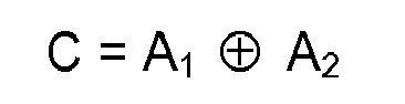
and

and
6. A method according to any of the preceding claims, wherein data transmission of at
least some of the packages Ai, C is performed in respective different frequency channels.
7. Hearing system comprising a hearing instrument and another device,
the hearing instrument having
a receiver for wireless data communication between the hearing instrument and the other device in a wireless network, and
a communication controller that is configured for controlling the wireless data communication, and wherein
the other device is configured for transmission of data in data packages A1, A2, ... , AN, C, wherein each of the data packages A1, A2, ... , AN, C is transmitted in an individual frequency channel, and wherein data package C is a function of A1, A2, ... , AN:

and wherein the communication controller is further configured for controlling the receiver for
data reception of data packages A1, A2, ... , AN, and C; and for performing error detection, and
in case of detection of an error in data package AE, where AE is one of the received data packages A1, A2, ... , AN:

the hearing instrument having
a receiver for wireless data communication between the hearing instrument and the other device in a wireless network, and
a communication controller that is configured for controlling the wireless data communication, and wherein
the other device is configured for transmission of data in data packages A1, A2, ... , AN, C, wherein each of the data packages A1, A2, ... , AN, C is transmitted in an individual frequency channel, and wherein data package C is a function of A1, A2, ... , AN:
and wherein the communication controller is further configured for controlling the receiver for
data reception of data packages A1, A2, ... , AN, and C; and for performing error detection, and
in case of detection of an error in data package AE, where AE is one of the received data packages A1, A2, ... , AN:
Recovering the data package AE in accordance with:
8. Hearing system according to claim 7, wherein the communication controller is configured
for controlling the receiver for data reception of data package C solely in response
to detection of an error in AE, one of the received data packages A1, A2, ... , AN.
9. Hearing system according to claim 7 or 8, wherein function

and function

are identical functions.
and function
are identical functions.
10. Hearing system according to claim 9, wherein

is an exclusive-or function so that
and

is an exclusive-or function so that
and
11. Hearing system according to claim 10, wherein N is equal to 2 so that

and

and
12. Hearing system according to any of claims 7 - 11, wherein data transmission of at
least some of the data packages Ai, C is performed in respective different frequency channels.
13. Hearing system according to any of claims 7 - 12, wherein data transmission is performed
in accordance with a frequency hopping scheme and, subsequent to the transmission
of one data package AP, a frequency hop is performed before transmission of the next data package AP+1 of the data packages A1, A2, ... , AN so that each of the data packages A1, A2, ... , AN is transmitted in an individual frequency channel.
14. Hearing system according to any of claims 7 - 13, wherein the hearing instrument further
comprises a transmitter and wherein the communication controller is further configured
for controlling the transmitter to transmit data in data packages A1, A2, ... , AN, C, wherein data package C is a function of A1, A2, ... , AN:

REFERENCES CITED IN THE DESCRIPTION
This list of references cited by the applicant is for the reader's convenience only. It does not form part of the European patent document. Even though great care has been taken in compiling the references, errors or omissions cannot be excluded and the EPO disclaims all liability in this regard.
Patent documents cited in the description