|
(11) | EP 2 487 500 A1 |

| (12) | EUROPEAN PATENT APPLICATION |
|
|
|
|
|||||||||||||||||||||||
| (54) | Method to generate magnetic fields of high uniformity and compensation of external dispersed field, and system for its embodiment |
| (57) The present invention relates to a method to generate magnetic fields of high uniformity
within the object examined and compensation of external dispersed field, and a system
for its embodiment, which method is applicable in magnetic resonance tomography. The
method to generate magnetic fields of high uniformity within the object examined in
which two pairs of coils (1) and (2) are used in which the current flows in the same
direction and sense. The system is composed of two pairs of coils (1) and (2), which,
preferably, have the same radiuses, are situated coaxially, are attached to the housing
of the tomograph in a permanent, detachable manner, and in which the current flows
in the same direction and sense.
|
[0001] The present invention relates to a method to generate magnetic fields of high uniformity within the object examined and compensation of external dispersed field, and a system for its embodiment, which method is applicable in magnetic resonance tomography.
[0002] The simplest way to generate a uniform magnetic field is with the use of a Helmholtz coil system. However, a uniform field is obtained only in a small region, between the coils. For instance, uniformity of the magnetic field [generated] with the use of such coils having a radius R = 1m will be of the order of ±1000 ppm for a region between the coils -0.2m ≤ z ≤ 0.2m . Such uniformity is too low for applications in nuclear magnetic resonance (NMR) tomography or in electron paramagnetic resonance (EPR) tomography. The uniformity of magnetic field which is required in either of the two examination techniques must be in the order of several dozen ppm or lower. A possible way to improve the uniformity of magnetic field within the object examined is by using two pairs of coils having different radiuses and different current flow directions (George A. Rinard et al. Magnet and Gradient Coil System for Low-Field EPR Imaging, Conc. Magn. Res. 15 (2002), 51 - 58). The uniformity of the magnetic field obtained in this case for two pairs of cells having radiuses R1=40.64cm and R2=19.77cm, within -0.075m ≤ z ≤ 0.075m was in the order of ±40ppm. This is a considerable progress, compared with Helmholtz's single coils having a radius of R=40.64cm, for which uniformity is in the order of ±600ppm. The above solution enables magnetic fields to be generated with sufficient uniformities, however, a smaller diameter of the second coil narrows the size of the object to be examined which, for the size of human body entails the construction of a large, energy consuming system. Therefore, in the Center for EPR Imaging, Chicago (Epel B, Sundramoorthy SV, Mailer C, Halpern HJ, A versatile high speed 250-MHz pulse imager for biomedical applications, Concepts in Magnetic Resonance Part B: Magnetic Resonance Engineering. 33B(3):163-176, 2008) a system was built for the examination of small organisms which was rescaled twice, compared with the parameters presented in the paper referred to above. In addition, opposite current flow directions in both coil pairs decrease the magnetic field intensity, which involves the use of more power.
[0003] Such limitations are not observed in the layout of the coil systems in an electromagnet, which enables very high uniformities of the magnetic field to be obtained within the working space of a magnetic resonance tomograph.
[0004] The present invention relates to a method to determine the positions of the coil system in an electromagnet along the z axis as well as the number of ampere-turns of the same radiuses, enabling the generation of a highly uniform magnetic field within the working space of a tomograph.
[0005] Furthermore, the present invention relates to a method to design additional coils with rescaled dimensions to enable compensation of the dispersed field outside the electromagnet, while preventing any considerable decrease of the field value inside the tomograph.
[0006] The gist of the invention is a method to generate magnetic fields of high uniformity within the object examined, in which two pairs of coils are used in which the current flows in the same direction and sense while the radiuses of the coil pairs are preferably the same.
[0007] Preferably, the distances from the plane of symmetry d1 and d2 for the pair of coils (1) and (2) and the numbers of their ampere-turns are found from the equation system:
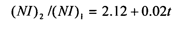
where d1 is the distance between the first pair of coils and the plane of symmetry, d2 is the distance between the second pair of coils and the plane of symmetry, R is the coil radius, (NI)1 is the ampere-turn size for the first coil, (NI)2 is the ampere-turn size for the second coil, and 1 ≤ t ≤ 82 where t - is a parameter, linearly related to the ratio of ampere-turns for the second coil and that for the first coil.
[0008] Also preferably, the distances from the plane of symmetry d1 and d2 for the pair of coils and the numbers of their ampere-turns are found from the equation system:
where d1 is the distance between the first pair of coils and the plane of symmetry, d2 is the distance between the second pair of coils and the plane of symmetry, R is the coil radius, (NI)1 is the ampere-turn size for the first coil, (NI)2 is the ampere-turn size for the second coil, and 1 ≤ t ≤ 394 where t - is a parameter, linearly related to the ratio of ampere-turns for the second coil and that for the first coil.
[0009] Also preferably, two additional pairs of coils in which the current flows in the same direction and the radiuses of the coil pairs are preferably the same are used for the compensation of any residual field outside the tomograph.
[0010] Furthermore, also preferably, additional two twin-pairs of coils are used for the compensation of any residual field outside the tomograph after rescaling their dimensions and ampere-turns according to the equations:
where Iwew is the current intensity in the inner pair of coils having a radius R1, Izew is the current intensity in the outer pair of coils having a radius R2, d1 is the distance between the first pair of coils and the plane of symmetry, d2 is the distance between the second pair of coils and the plane of symmetry, where d3 is the distance between the first pair of compensating coils and the plane of symmetry, d4 is the distance between the second pair of coils and the plane of symmetry.
[0011] In particular, preferably, additional two twin-pairs of coils are used for the compensation of any residual field outside the tomograph after rescaling their dimensions and ampere-turns according to the equations.
where Iwew is the current intensity in the inner pair of coils having a radius R1, Izew is the current intensity in the outer pair of coils having a radius R2, d1 is the distance between the first pair of coils and the plane of symmetry, d2 is the distance between the second pair of coils and the plane of symmetry, where d3 is the distance between the first pair of compensating coils and the plane of symmetry, d4 is the distance between the second pair of coils and the plane of symmetry.
[0012] The system, designed to generate magnetic fields of high uniformity within the examined object is characterized by that it is composed of two pairs of coils which, preferably, have the same radiuses, are situated coaxially, are attached to the housing of the tomograph in a permanent, detachable manner, and in which the current flows in the same direction and sense, and that an additional system of two pairs of coils which, preferably, have the same radiuses, are situated coaxially, are attached to the housing of the tomograph in a permanent, detachable manner, and in which the current flows in the same direction and sense, is used for the compensation of any residual field outside the tomograph.
[0013] The use of the layout of the coil system of the electromagnet has enabled the following technical and utility effects to be achieved: construction of a system of the principal coils of a tomograph with a facilitated access to the examined objects, generation of highly uniform magnetic fields of which the non-uniformity is in the order of fractions of ppm, reduced power indispensable for operating the tomograph, compensation of any dispersed residual field outside the tomograph. The method of the invention enables unambiguous establishing of all the parameters which are indispensable for the design and manufacture of generating and compensating coils.
[0014] The invention is shown in the figures: Fig.1 - shows the coil geometry, Fig.2. - shows the system with a twin system, intended to reduce any residual magnetic field, Fig. 3 - shows diagrams of the value of the distance of two coils from the 'z' axis - the other two are positioned symmetrically about the 'xy' plane for a first family of solutions, Fig. 4 - same case as above, for a second family of solutions, Fig. 5 - distribution of non-uniformity of magnetic field for a representative configuration, Fig. 6 - fading value of magnetic field outside the tomograph with and without shielding.
[0015] To generate a uniform magnetic field, a system of two coil pairs is used such that they have same radiuses, their distance from the plane of symmetry is d1 for the nearer pair and d2 for the farther pair, and of which the layout is shown in Fig. 3 for the first case and in Fig. 4 for the second one. For such a system of four coils, there exist two families of solutions, determining the position of each coil pair. The first family of solutions relate to a model in which the coil positions move closer to the plane of symmetry - Fig. 3, the second family are connected with the positions of coil pairs which move away from the plane of symmetry - Fig. 4.
[0016] For the first family of solutions, the positions of the coil pairs are found from the following formula:
where d1 is the distance between the first pair of coils and the plane of symmetry, d2 is the distance between the second pair of coils and the plane of symmetry, R is the coil radius, (NI)1 is the ampere-turn size for the first coil, (NI)2 is the ampere-turn size for the second coil, and 1 ≤ t ≤ 82 [where] t - is a parameter, linearly related to the ratio of ampere-turns for the second coil and that for the first coil. The above solutions, described by Equation (1), are related to solutions for the positions of each coil for a compact system. For an open system, where the respective coils move away from each other, the geometric coordinates of the inner coil pair d1 and the coordinates of the outer coil pair d2 should be found using the formula for the second family of solutions:
where the parameter 1 ≤ t ≤ 394 .
[0017] The use of the above formulas enables determination of the positions of both coil pairs, which generate a highly uniform magnetic field of which the uniformity is in the order of ±400 ppb (parts per billion), i.e., a fraction of ppm, within the volume of a sphere of which the radius is 20% of the coil radius, or even as low as ±1 ppb (0.001 ppm) within the volume of a sphere of which the radius is 7% of the coil radius. The obtained uniformity values relate to the region of a cylinder of which the radius is 20% and 7% of the radiuses of powering coils, respectively, while the length of the cylinder is 40% and 14% of the coil radius, respectively. For coils of which the radius is 1m, the above provides a uniformity region of which the radius is 20cm and the length is 40cm.
[0018] Compared with the paper quoted, Equations (1) and (2) provide uniformities which are a couple of orders of magnitude higher. Another advantage of designing coil geometry with the use of the algorithms presented herein is that neither transverse nor axial access is limited (in contrast to the smaller diameter of outer coils in the paper quoted). Furthermore, one should be aware of the fact that a magnetic field generated by the proposed coil families is higher (because current flows in the same direction in every coil), compared with the magnetic field generated by the coils proposed by George A. Rinard et al.
[0019] Due to equipment-related problems, no tomograph presently used in EPR imaging has any mechanisms intended to reduce the magnetic field, dispersed outside the tomograph. A commonly used method to eliminate the impact of dispersed magnetic field involved the shielding of rooms. The method of the invention enables a significant reduction of the value of magnetic field outside the coil system, while only negligibly reducing induction of magnetic field inside the system. The method consists in placing one of the proposed coil systems inside a suitable larger (rescaled) system. In the system with the larger radius, the current flow will have the same direction but the opposite sense, compared with current in the coil system with the smaller radius. The value of current in the coils with the larger radius is found from the relationship:
where Iwew is the value of the current which flows in the coils with the smaller radius R1, while Izew is the value of the current which flows in the coils with the larger radius R2. So designed, the system provides the compensation of any residual magnetic field outside the [electro]magnet system according to the exponent r-7. Fig. 6 shows the fading of induction of a magnetic field outside the tomograph in the case of two or four coil pairs being used for generating the field.
[0020] Application of all of the above advantages of the invention referred to above, connected with the layout of the coil pairs having the same radiuses and current flowing in the same direction, enables significant reductions of operating costs (lower costs of shielding, lower values of current for generating higher values of magnetic fields, small sizes enabling easy access to the inside of the coil system, transverse and axial access to the uniform field region).
1. A method to generate magnetic fields of high uniformity within the object examined
is characterised in that two pairs of coils (1) and (2) are used in which the current flows in the same direction
and sense.
2. A method according to claim 1, wherein the coil pairs (1) and (2), preferably, have the same radiuses.
3. A method according to claim 1 or 2, wherein the distances from the plane of symmetry d1 and d2 for the pair of coils (1) and (2) and the numbers of their ampere-turns, preferably,
are found from the equation system:


where d1 is the distance between the first pair of coils and the plane of symmetry, d2 is the distance between the second pair of coils and the plane of symmetry, R is the coil radius, (NI)1 is the ampere-turn size for the first coil, (NI)2 is the ampere-turn size for the second coil, and 1 ≤ t ≤ 82 where t - is a parameter, linearly related to the ratio of the ampere-turns of the second coil and those of the first coil.
where d1 is the distance between the first pair of coils and the plane of symmetry, d2 is the distance between the second pair of coils and the plane of symmetry, R is the coil radius, (NI)1 is the ampere-turn size for the first coil, (NI)2 is the ampere-turn size for the second coil, and 1 ≤ t ≤ 82 where t - is a parameter, linearly related to the ratio of the ampere-turns of the second coil and those of the first coil.
4. A method according to claim 1 or 2, wherein the distances from the plane of symmetry d1 and d2 for the pair of coils (1) and (2) and the numbers of their ampere-turns, preferably,
are found from the equation system:


where d1 is the distance between the first pair of coils and the plane of symmetry, d2 is the distance between the second pair of coils and the plane of symmetry, R is the coil radius, (NI)1 is the ampere-turn size for the first coil, (NI)2 is the ampere-turn size for the second coil, and 1 ≤ t ≤ 394 where t - is a parameter, linearly related to the ratio of the ampere-turns of the second coil and those of the first coil.
where d1 is the distance between the first pair of coils and the plane of symmetry, d2 is the distance between the second pair of coils and the plane of symmetry, R is the coil radius, (NI)1 is the ampere-turn size for the first coil, (NI)2 is the ampere-turn size for the second coil, and 1 ≤ t ≤ 394 where t - is a parameter, linearly related to the ratio of the ampere-turns of the second coil and those of the first coil.
5. A method according to claim 1 or 2 or 3, wherein two additional pairs of coils (3) and (4), in which the current flows in the same
direction, are used for the compensation of any residual field outside the tomograph.
6. A method according to claim 1 or 2 or 3 or 5, wherein the additional coil pairs (3) and (4) preferably have the same radiuses.
7. A method according to claim 1 or 2 or 3 or 5 or 6, wherein two additional coil pairs (3) and (4), of which the sizes and ampere-turns are preferably
rescaled according to the equations, are used for the compensation of any residual
field outside the tomograph.


where Iwew is the current intensity in the inner pair of coils having a radius R1, Izew is the current intensity in the outer pair of coils having a radius R2, d1 is the distance between the first pair of coils and the plane of symmetry, d2 is the distance between the second pair of coils and the plane of symmetry, where d3 is the distance between the first pair of compensating coils and the plane of symmetry, d4 is the distance between the second pair of coils and the plane of symmetry.
where Iwew is the current intensity in the inner pair of coils having a radius R1, Izew is the current intensity in the outer pair of coils having a radius R2, d1 is the distance between the first pair of coils and the plane of symmetry, d2 is the distance between the second pair of coils and the plane of symmetry, where d3 is the distance between the first pair of compensating coils and the plane of symmetry, d4 is the distance between the second pair of coils and the plane of symmetry.
8. A method according to claim 1 or 2 or 4 or 5 or 6, wherein additional two twin-pairs of coils (3) and (4), of which the sizes and ampere-turns
are preferably rescaled according to the equations, are used for the compensation
of any residual field outside the tomograph.


where Iwew is the current intensity in the inner pair of coils having a radius R1, Izew is the current intensity in the outer pair of coils having a radius R2, d1 is the distance between the first pair of coils and the plane of symmetry, d2 is the distance between the second pair of coils and the plane of symmetry, where d3 is the distance between the first pair of compensating coils and the plane of symmetry, d4 is the distance between the second pair of coils and the plane of symmetry.
where Iwew is the current intensity in the inner pair of coils having a radius R1, Izew is the current intensity in the outer pair of coils having a radius R2, d1 is the distance between the first pair of coils and the plane of symmetry, d2 is the distance between the second pair of coils and the plane of symmetry, where d3 is the distance between the first pair of compensating coils and the plane of symmetry, d4 is the distance between the second pair of coils and the plane of symmetry.
9. A system, designed to generate magnetic fields of high uniformity within the examined
object, wherein the system is composed of two pairs of coils (1) and (2), which, preferably, have
the same radiuses, are situated coaxially, are attached to the housing of the tomograph
in a permanent, detachable manner, and in which the current flows in the same direction
and sense.
10. A system according to claim 9, wherein an additional system composed of two pairs of coils (3) and (4) which, preferably,
have the same radiuses, are situated coaxially, are attached to the housing of the
tomograph in a permanent, detachable manner, and in which the current flows in the
same direction and sense, is used for the compensation of any residual field outside
the tomograph.
REFERENCES CITED IN THE DESCRIPTION
This list of references cited by the applicant is for the reader's convenience only. It does not form part of the European patent document. Even though great care has been taken in compiling the references, errors or omissions cannot be excluded and the EPO disclaims all liability in this regard.
Non-patent literature cited in the description
- GEORGE A. RINARD et al.Magnet and Gradient Coil System for Low-Field EPR ImagingConc. Magn. Res., 2002, vol. 15, 51-58 [0002]
- EPEL BSUNDRAMOORTHY SVMAILER CHALPERN HJA versatile high speed 250-MHz pulse imager for biomedical applicationsConcepts in Magnetic Resonance Part B: Magnetic Resonance Engineering, 2008, vol. 33B, 3163-176 [0002]