|
(11) | EP 2 492 921 A1 |

| (12) | EUROPEAN PATENT APPLICATION |
|
|
|
|
|||||||||||||||||||||||
|
||||||||||||||||||||||||
| (54) | Holographic microscopy of holographically trapped three-dimensional structures |
| (57) A method and system for performing three-dimensional holographic microscopy of an
optically trapped structure. The method and system use an inverted optical microscope,
a laser source which generates a trapping laser beam wherein the laser beam is focused
by an objective lens into a plurality of optical traps. The method and system also
use a collimated laser at an imaging wavelength to illuminate the structure created
by the optical traps. Imaging light scattered by the optically trapped structure forms
holograms that are imaged by a video camera and analyzed by optical formalisms to
determine light field to reconstruct 3-D images for analysis and evaluation.
|
CROSS REFERENCE TO RELATED PATENT APPLICATIONS
[0001] This application claims the benefit under 35 U.S.C. 119(e) of U.S. Application 60/897,784 filed January 26, 2007, incorporated by reference herein in its entirety.
[0002] The U.S. Government has certain rights in this invention pursuant to grants from the National Science Foundation through Grant Number DB1-0629584 and Grant Number DMR-0606415.
[0003] This invention is directed to a holographic optical trapping system using optical traps generated by computer-established holograms to organize materials and apply microscope optics to inspect and analyze the materials in three dimensions (3-D), More particularly, a holographic video microscope system uses real-time resolved volumetric images of 3-D microstructures to carry out analysis and inspection of material assemblies.
BACKGROUND OF THE INVENTION
[0004] Holographic optical trapping uses computer-generated holograms to trap and organize micrometer-scale objects into arbitrary three-dimensional configurations. No complementary method has been available in the prior art for examining optically trapped structures except for conventional two-dimensional microscopy. Three-dimensional imaging would be useful for a variety of uses, such as verifying the structure of holographically organized systems before fixing them in place. It also would be useful for interactively manipulating and inspecting three-dimensionally structured objects such as biological specimens. Integrating three-dimensional imaging with holographic trapping might seem straightforward because both techniques can make use of the same objective lens to collect and project laser light, respectively. However, conventional three-dimensional imaging methods, such as confocal microscopy, involve mechanically translating the focal plane through the sample. Holographic traps, however, are positioned relative to the focal plane, and would move as well. The trapping pattern would have to be translated to compensate for the microscope's mechanical motion, which would add substantial complexity, would greatly reduce imaging speed, and would likely disrupt the sample undergoing examination and analysis.
SUMMARY OF THE INVENTION
[0005] Digital holographic microscopy solves all of the prior art technical problems, providing real-time three-dimensional (3-D) imaging data without requiring any mechanical motion, including no need to translate the focal plane through the sample under analysis. A particularly compatible variant of in-line holographic microscopy replaces the conventional illuminator in a bright-field microscope with a collimated laser. Light scattered out of the laser beam by the object interferes with the remainder of the incident illumination to produce a heterodyne scattering pattern that is magnified by the objective lens and recorded with a video camera. Provided that this interference pattern is not obscured by multiple light scattering, it contains comprehensive information on the scatterers' three-dimensional configuration. Each two-dimensional snapshot in the resulting video stream encodes time-resolved volumetric information that can be analyzed directly, or decoded numerically into three-dimensional representations. This system and method enables ready commercial use of digital holographic microscopy in a holographic optical manipulation system, and uses the combined capabilities to directly assess both techniques' accuracy and establish any limitations.
According to one aspect, the invention comprises a method of performing 3-D holographic microscopy of an optically trapped structure, including the steps of providing an optical microscope; generating a laser beam having an associated imaging wavelength input to the inverted optical microscope; generating a plurality of optical traps, the improvement comprising using wave fronts of a trapping laser beam having a phase only hologram encoding a desired optical trapping pattern and the trapping laser beam having the associated trapping wavelength; providing an objective lens for the inverted optical microscope, the objective lens both projecting the plurality of optical traps and collecting in-line holographic images of the trapped structure; and providing images of the trapped structure to a CCD camera for three-dimensional holographic microscopy of the trapped structure.
The method may further include the step of interposing a dichroic mirror between the objective lens and the CCD camera, the dichroic mirror tuned to the trapping laser beam's trapping wavelength.
The images may include ghosting which can be minimized by translating the trapped structure from the focal plane.
The imaging laser beam may be provided by a helium-neon laser having a collimated beam output.
The inverted optical microscope may include a focal plan and the method may involve no mechanical motion for performing three-dimensional holographic microscopy of the trapped structure.
The method may further include the step of subtracting off a reference image from the image formed at the CCD camera, thereby removing a varying background illumination when none of the trapped structure is present.
The images of the trapped structure may include two-dimensional real-valued images for reconstruction of a three-dimensional complex-valued light field.
The method may include the additional step of analyzing the images using a Rayleigh-Sommerfeld formalism.
The Rayleigh-Sommerfeld formalism may include analyzing propagation of the trapped structure along an optical axis of the inverted optical microscope.
The trapped structure may give rise to a scattered field u(r,z) at a distance z upstream of a focal plane of the optical microscope and the scattered field u(r,z) is reconstructed by
The method may further include the step of reconstructing a 3-D light field v(r,z) of the images by solving
The light field v(r,z) may be reconstructed from a single holographic snapshot of the image.
The method may further include the step of tracking movement of the trapped structure.
The trapped structure may comprise a plurality of objects which are occluded and the three-dimensional images are reconstructed and the objects all resolved in the reconstructed light field.
The method may further include the step of acquiring image data from multiple focal planes of the optical microscope, thereby enhancing accuracy of the images of the trapped structure.
According to another aspect the invention comprises a system for performing three-dimensional holographic microscopy of an optically trapped structure, including an optical microscope; a laser source for producing a trapping laser beam; a spatial light modulator for providing the phase-only hologram for imprintation on the trapping laser beam; a laser source for producing an imaging laser beam, the improvement comprising the trapping laser beam having a phase only hologram encoding a desired optical trapping pattern; an objective lens associated with the optical microscope which comprises an inverted microscope; a CCD camera for detecting laser light arising from imaging of the trapped structure and the CCD camera outputting image data; and a computer for analyzing the image data using computer software executed by the computer.
The laser source may comprise a laser which produces a collimated beam of coherent light.
The system may further include a dichroic mirror disposed between the objective lens and the CCD camera.
The computer software may comprise mathematical formalisms including Rayleigh-Sommerfeld determinations of light field v(r,) for the laser beam received by the CCD camera.
The Rayleigh-Sommerfeld determinations may comprise embedded computer software executed by the computer to calculated
[0006] Various detailed aspects of the invention are described hereinafter, and these and other improvements and features of the invention are described in detail hereinafter, including the drawings described in the following section.
BRIEF DESCRIPTION OF THE DRAWINGS
[0008] FIGURE 2A illustrates a conventional bright-field image of five colloidal spheres trapped in an xy plane (the scale bar is 5 micrometers); FIGURE 2B illustrates the pattern of FIG. 2A rotated about a y axis by 45°; FIG. 2C illustrates a bright-field image of the rotated pattern of FIG. 2B as seen in the xy plane; FIG. 2D illustrates a coherent image of the same structure as seen in the xy plane; and FIG. 2E illustrates a holographic reconstruction of an xz slice through the tilted pattern (circles denote the intended particle coordinates);
[0009] FIGURE 3A illustrates a holograph recorded in an xy plane of a single sphere trapped at x=17 micrometers above a focal plane; FIG. 3B illustrates the real part of the scattered field reconstructed from FIG. 3A; FIG. 3C shows a hologram recorded with the sphere at x = 0; FIG. 3D shows an axial section of the scattered field obtained by translating the subject colloidal sphere past the focal plane in Δz = 0.122 µm micrometer steps; FIG. 3E shows an equivalent reconstruction using conventional illumination; and FIG. 3F illustrates axial intensity profiles from FIG. 3B and 3D, demonstrating accuracy of the axial reconstruction; and
[0010] FIGURE 4A shows resolution limits for occluded objects in the xy plane and FIG. 4B for the zy plane.
DETAILED DESCRIPTION OF PREFERRED EMBODIMENTS
[0011] FIG. 1 shows a schematic representation of an integrated system 10 constructed in accordance with the invention. The system 10 is based on an inverted optical microscope (such as, Zeiss Axiovert S 100-TV) outfitted with a 100x NA 1.4 oil immersion objective lens 20. This lens 20 is used both to project holographic optical traps, and also to collect in-line holographic images of trapped objects. Holographic traps are preferably powered by a frequency-doubled diode-pumped solid state laser 25 (such as, a Coherent Verdi) operating at a wavelength of 532 nm to generate input laser beam 30. A liquid crystal spatial light modulator 35 (such as a Hamamatsu PAL-SLM X7550) imprints the beam's wavefronts with phase-only holograms encoding the desired trapping pattern. The modified trapping beam 40 then is relayed to the input pupil of the objective lens 20 and is focused into optical traps.
[0012] The trapping beam 40 is preferably relayed to the objective lens 20 with a dichroic mirror 50 tuned to the trapping laser's wavelength. Other wavelengths pass through the dichroic mirror 50 and form images on a CCD camera 60 (such as, NEC TI-324AII). In a most preferred embodiment a standard combination of incandescent illuminator and condenser lens 62 has been replaced with a helium-neon laser providing 5 mW collimated beam of coherent light at a wavelength of λ = 632 nm in air. The system 10 further includes a computer 65 for manipulation of sensed image data and analyzing the image data by executing calculations of all equations provided herein by conventional software known in the art. The computer 65 can also include any conventional executable memory, such as a ROM, RAM, or other well known memory capable of storing a program, data or other instructions which can be executed to fulfill the analyzation functions described herein.
[0013] FIGURE 2A demonstrates holographic imaging of colloidal spheres 70 holographically trapped in a three-dimensional pattern. These 1.53 µm diameter silica spheres 70 (Bangs Labs Lot No. L011031B) are dispersed in a 50 µm thick layer of water confined within a slit pore formed by sealing the edges of a #1.5 cover slip to the surface of a clean glass microscope slide. Each of the spheres 70 is trapped in a separate point-like optical tweezer, and the individual optical traps are positioned independently in three dimensions. FIG. 2A shows a conventional bright-field image of the sphere or the particles 70 arranged in a focal plane. Projecting a sequence of holograms with the trapping positions slightly displaced enables us to rotate the entire pattern in three dimensions, as shown in FIG. 2B. As the particles 70 move away from the focal plane, their images blur, as can be seen in FIG. 2C. It is difficult to determine from this image whether the most distant particles 70 are present at all.
[0014] FIG. 2D shows the same field of view, but with laser illumination. Each of the particles 70 appears in this image as the coherent superposition of the laser light it scatters with the undiffracted portion of the input laser beam 30. Other features in the image result from reflections, refraction and scattering by surfaces in the optical train of the system 10. These can be minimized by subtracting off a reference image obtained with no particles or trapped structure in the field of view.
[0015] Enough information is encoded in two-dimensional real-valued images such as FIGS. 2A - 2E to at least approximately reconstruct the three-dimensional complex-valued light field. The image in FIG. 2E is an example showing a numerically reconstructed vertical cross-section through the array of particles 70. This demonstrates the feasibility of combining holographic microscopy with holographic optical trapping. The reconstruction is consistent with the anticipated 45° inclination of the array, and with the calibrated 5.9 µm separation between the particles 70. Intended particle coordinates are shown as circles superimposed on the image. This quantitative comparison demonstrates the utility of holographic microscopy for verifying holographic assemblies. Because holographic images, such as FIG. 2D, can be obtained at the full frame rate of the video camera 60, holographic microscopy offers the benefit of real-time data acquisition over confocal and deconvolution microscopies.
[0016] In a most preferred embodiment, very accurate results can be obtained from use of the Rayleigh-Sommerfeld formalism because holograms, such as in FIG. 2D form at ranges comparable to the light wavelength. The field u(r, z)) scattered by an object at height z above the microscope's focal plane propagates to the focal plane, where it interferes with the reference field, a(r), comprised of the undiffracted portion of the laser illumination. The Rayleigh-Sommerfeld propagator describing the object field's propagation along optical axis 80 is:
where R2 = r2 + z2 and k=2π n/λ is the light's wavenumber in a medium of refractive index n. The field in the focal plane is the convolution u(r,0)⊗ hz(r). The observed interference pattern, therefore, is
[0017] The first term in Eq. (2) can be approximated by measuring the intensity when no objects are in the field of view. FIG. 2D was obtained by subtracting such a reference image from the measured interference pattern. If we further assume that the scattered field is much dimmer than the reference field, the second term in Eq. (2) dominates the third. In that case,
provides a reasonable basis for reconstructing u(r).
[0018] Analyzing Eq. (3) can be simplified by assuming a(r) = 1 for the reference field. In our application, however, the illuminating laser trapping beam 40 passes through an inhomogeneous sample before reaching the focal plane. Any resulting amplitude variations can be eliminated by normalizing I(r) with |a(r)|. Structure in the illumination's phase cannot be compensated in this way, and must be assumed to vary more gradually than any features of interest.
[0019] Reconstructing the three-dimensional intensity field is most easily performed using the Fourier convolution theorem, according to which
where U(q) is the Fourier transform of u(r, 0) and
is the Fourier transform of the Rayleigh-Sommerfeld propagator.
[0020] The estimate for the Fourier transform of the object field at height z' above the focal plane is obtained by applying the appropriate Rayleigh-Sommerfeld propagator to translate the effective focal plane:
[0021] The first term in Eq. (8) is the reconstructed field, which comes into best focus when z' = z. The second is an artifact that is increasingly blurred as z' increases. Unfortunately, this term creates a mirror image around the plane z = 0 with the result that objects below the focal plane cannot be distinguished from objects above. This ghosting is apparent in FIG. 2E.
[0023] Equation (9) can reconstruct a volumetric representation of the instantaneous light field in the sample under inspection from a single holographic snapshot, I(r). The image in FIG. 2E is a cross-section through the reconstructed intensity distribution, |ν(r,z)|.
[0024] Each sphere in FIG. 2E appears as a bright axial streak centered on a relatively dark dimple at the object's three-dimensional position. Circles superimposed on FIG. 2E denote the intended three-dimensional positions of the spheres 70, which were used to compute the trap-forming hologram that arranged the spheres 70. The very good agreement between the optical traps' design and features in the resulting reconstructed field attests to the accuracy of both the projection and imaging methods.
[0025] Contrary to previous reports in the prior art, images such as those in FIGS. 3A to 3F suggest that the axial resolution of our holographic reconstruction approaches the diffraction-limited in-plane resolution. FIG. 3A shows a hologram obtained for one of the spheres 70 held by an optical tweezer at height z = 17 µm above the focal plane. FIG. 3B is an axial section through the real part of field reconstructed from
{ν(r,z)}=|ν(r,z)|cos(φ(r,z)). This representation has the benefit of most closely resembling the scattering field observed in conventional three-dimensional bright-field microscopy. The sphere, in this case, is centered at the cusp between bright and dark regions. This crossover in the scattered field's sign creates a dark dimple in the intensity.
[0026] The effective axial resolution can be assessed by scanning the sphere past the focal plane and stacking the resulting images to create a volumetric data set. FIG. 3C is a hologram of the same sphere from FIG. 3A at z = 0. Compiling a sequence of such images in axial steps of Δz = 0.122 µm yields the axial section in FIG. 3D.
[0027] Structure in the spheres' images along the axial direction can be analyzed to track the spheres 70 in z, as well as in x and y. For the micrometer-scale particles or the spheres 70 studied here, for example, the centroid is located in the null plane between the downstream intensity maximum and the upstream intensity minimum along the scattering pattern's axis. Holographic microscopy of colloidal particles therefore can be used to extract three-dimensional trajectories more accurately than is possible with conventional two-dimensional imaging and far more rapidly than with scanned three-dimensional imaging techniques. In particular, in-plane tracking can make use of conventional techniques, and tracking in depth requires additional computation but no additional calibration.
[0028] Analyzing images becomes far more challenging when objects occlude each other along the optical axis, as FIGS. 4A and 4B demonstrate. Here, the same pattern of the spheres 70 from FIGS. 2A - 2E has been rotated by 90°, so that four of the spheres 70 are aligned along the optical axis 80. FIG. 4A is a detail from the resulting hologram and FIG. 4B is the holographic reconstruction in the vertical plane of the structure. The central observation from FIG. 4B is that all four of the spheres 70 are resolved, even though they directly occlude each other. A fifth sphere 70, not directly occluded by the others was included as a reference, and is visible to the right of the others in FIGS. 4A and 4B.
[0029] The uppermost spheres 70 in FIG. 4B appear substantially dimmer than those trapped closer to the focal plane; and FIGS. 4A and 4B compensate for this by presenting the amplitude |ν(r, z)|, rather than the intensity, of the light field. The reference sphere 70, however, is no brighter than its occluded neighbor, and no dimmer than any of the spheres 70 in FIGS. 2A - 2E. Rather, the lower spheres 70 act as lenses, gathering light scattered from above and focusing it onto the optical axis 80. As a result, these spheres 70 appear substantially brighter than normal, and their images are distorted. Equation (9) does not take such multiple light scattering into account when reconstructing the light field.
[0030] The resulting uncertainty in interpreting such results can be mitigated by acquiring images from multiple focal planes, or by illuminating the sample under investigation from multiple angles, rather than directly in-line. Results also would be improved by more accurate recordings. Each pixel in our holographic images contains roughly six bits of usable information, and no effort was made to linearize the camera's response. The camera 60 was set to 1/2000 s shutter speed, which nonetheless allows for some particle motion during each exposure. A wider dynamic range, calibrated intensity response and faster shutter all would provide sharper, more accurate holograms, and thus clearer three-dimensional reconstructions.
[0031] With these caveats, the image in FIG. 4B highlights the potential importance of holographic imaging for three-dimensional holographic manipulation. The most distant particle 70 appears displaced along the optical axis relative to the reference particle even though both were localized in optical tweezers projected to the same height. Three-dimensional visualizations confirm the structure of the projected trapping field. The apparent axial displacement was not evident for inclinations less than roughly 80°. It therefore reflects either a three-dimensional imaging artifact or, more likely, a real displacement of the particles 70 from their designed configuration. This is reasonable because light from the traps projected closer to the focal plane exerts forces on particles trapped deeper into the sample. This effect is exacerbated by particles trapped closer to the focal plane, which deflect light onto more distant particles, altering their effective potential energy wells. This effect has been exploited for in-line optical binding of particles trapped along thread-like Bessel beams. Holographic imaging provides a means for measuring such distortions, and thus a basis for correcting them. This can be critically important for processes such as the holographic assembly of photonic heterostructures which rely on accurate placement of microscope such particles or other objects.
[0032] The foregoing description of embodiments of the present invention have been presented for purposes of illustration and description. It is not intended to be exhaustive or to limit the present invention to the precise form disclosed, and modifications and variations are possible in light of the above teachings or may be acquired from practice of the present invention. The embodiments were chosen and described in order to explain the principles of the present invention and its practical application to enable one skilled in the art to utilize the present invention in various embodiments, and with various modifications, as are suited to the particular use contemplated.
1. A system for performing three-dimensional holographic microscopy of an optically trapped
structure, including an optical microscope having an objective lens, a laser source
for producing a trapping laser beam for a structure; the system characterized by a spatial light modulator for providing a phase-only hologram for imprinting on the
trapping laser beam; the laser source also for producing an imaging laser beam and
using the imaging laser beam providing volumetric three-dimensional images of the
optically trapped structure; a device for detecting laser light arising from imaging
of the trapped structure and the device outputting image data; and a computer for
analyzing the image data using computer software executed by the computer.
2. The system as defined in claim 1 further including a dichroic mirror disposed between
the objective lens and the device for detecting laser light.
3. The system as defined in claim 2 wherein the computer software comprises mathematical
formalisms including Rayleigh-Sommerfeld determinations of a light field for the laser
beam received by the device.
4. The system as defined in claim 1 or claim 2 or claim 3 wherein the Rayleigh-Sommerfeld
determinations comprise embedded computer software executed by the computer to calculate,
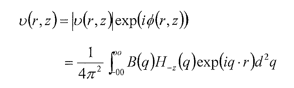
where v(r,z) light field as a function of radius "r" and position "z" and B(q),H-z(q) is a Rayleigh Sommerfeld propagator and φ is a phase angle.
where v(r,z) light field as a function of radius "r" and position "z" and B(q),H-z(q) is a Rayleigh Sommerfeld propagator and φ is a phase angle.
5. The system as defined in claim 2 or claim 3 wherein the dichroic mirror is constructed
to be tuned to a trapping wavelength of the trapping laser beam.
6. The system as defined in claim 1 or any preceding claim wherein the spatial light
modulator is programmed to create the trapping laser beam having a holographic pattern
to translate the trapped structure array from a focal plane of the objective lens.
7. The system as defined in claim 1 or any preceding claim further including a separate
laser beam for optical illumination of the trapped structure and viewing thereof.
8. The system as defined in claim 7 wherein the objective lens is positioned in the system
to process both the separate laser beam and the trapping laser beam.
9. The system as defined in claim 1 or any preceding claim wherein the device comprises
a CCD camera.
10. The system as defined in claim 1 or any preceding claim wherein no mechanical motion
structure is used for performing the three-dimensional holographic microscopy.
11. The system as defined in claim 1 or any preceding claim wherein the image data comprises
a plurality of images from different focal planes.
12. The system as defined in claim 1 or any preceding claim wherein the image data comprises
a single holographic snapshot of the trapped structure.
REFERENCES CITED IN THE DESCRIPTION
This list of references cited by the applicant is for the reader's convenience only. It does not form part of the European patent document. Even though great care has been taken in compiling the references, errors or omissions cannot be excluded and the EPO disclaims all liability in this regard.
Patent documents cited in the description