| (19) |
 |
|
(11) |
EP 2 956 407 B1 |
| (12) |
EUROPEAN PATENT SPECIFICATION |
| (45) |
Mention of the grant of the patent: |
|
23.11.2016 Bulletin 2016/47 |
| (22) |
Date of filing: 07.02.2014 |
|
| (51) |
International Patent Classification (IPC):
|
| (86) |
International application number: |
|
PCT/EP2014/052404 |
| (87) |
International publication number: |
|
WO 2014/124873 (21.08.2014 Gazette 2014/34) |
|
| (54) |
HYDROGEN QUALITY DIFFERENTIATION AT REFUELLING STATION
WASSERSTOFFQUALITÄTSUNTERSCHEIDUNG AN EINER AUFTANKSTATION
DIFFÉRENCIATION DE QUALITÉ D'HYDROGÈNE AU NIVEAU D'UNE STATION DE RAVITAILLEMENT EN
CARBURANT
|
| (84) |
Designated Contracting States: |
|
AL AT BE BG CH CY CZ DE DK EE ES FI FR GB GR HR HU IE IS IT LI LT LU LV MC MK MT NL
NO PL PT RO RS SE SI SK SM TR |
| (30) |
Priority: |
12.02.2013 EP 13154936
|
| (43) |
Date of publication of application: |
|
23.12.2015 Bulletin 2015/52 |
| (73) |
Proprietor: Shell Internationale Research Maatschappij B.V. |
|
2596 HR The Hague (NL) |
|
| (72) |
Inventor: |
|
- LOUIS, Jurgen Johannes Jacobus
NL-2596 HR The Hague (NL)
|
| (74) |
Representative: Matthezing, Robert Maarten et al |
|
Shell International B.V.
Intellectual Property Services
P.O. Box 384
2501 CJ The Hague
2501 CJ The Hague (NL) |
| (56) |
References cited: :
EP-A1- 1 394 105
WO-A1-2009/057127
US-A1- 2006 118 575
US-A1- 2007 042 241
|
EP-A1- 1 942 300
US-A1- 2005 056 661
US-A1- 2006 236 608
|
|
| |
|
|
- CASAMIRRA M ET AL: "Safety studies of a hydrogen refuelling station: Determination
of the occurrence frequency of the accidental scenarios", INTERNATIONAL JOURNAL OF
HYDROGEN ENERGY, ELSEVIER SCIENCE PUBLISHERS B.V., BARKING, GB, vol. 34, no. 14, 1
July 2009 (2009-07-01), pages 5846-5854, XP026351135, ISSN: 0360-3199 [retrieved on
2009-03-21]
|
|
| |
|
| Note: Within nine months from the publication of the mention of the grant of the European
patent, any person may give notice to the European Patent Office of opposition to
the European patent
granted. Notice of opposition shall be filed in a written reasoned statement. It shall
not be deemed to
have been filed until the opposition fee has been paid. (Art. 99(1) European Patent
Convention).
|
Field of the Invention
[0001] This invention relates to a process and system for dispensing hydrogen of more than
one quality.
Background of the Invention
[0002] In recent years, there has been a great deal of interest in the development of alternative
energy sources, or energy carriers, such as hydrogen. Automobiles and other vehicles
that use hydrogen as a fuel source have been developed, and methods for refuelling
these vehicles that can compete with gasoline fuelling stations on scale and/or cost
have been designed and are being further developed.
[0003] Nowadays, there is a range of possible supply chains for hydrogen to refuelling stations,
including delivery routes (e.g. truck or pipeline) and forecourt production routes
(e.g. hydrocarbon reforming or water electrolysis). Hydrogen of a purity high enough
for fuel cell cars and up to the relevant standards is delivered (in gaseous form,
commonly) to one or more storage tanks at the station, then compressed and stored
in high pressure buffer tanks. It is then cooled and dispensed. A single dispenser
may have more than one hose, providing hydrogen of different purities or at a different
pressure. Depending on the source of the hydrogen, an initial purification step at
the refuelling station may be necessary in order to produce a hydrogen stream of sufficient
purity for use in fuel cell cars.
[0004] Cars powered by proton exchange membrane (PEM) fuel cells depend on a supply of pure
hydrogen. While some impurities (e.g. inert gases) are an issue in that their presence
simply reduces the proportion of hydrogen present in the fuel and thus the efficiency
of the car, other impurities have more serious consequences for the lifetime of the
fuel cell. Cumulative and irreversible efficiency reduction through 'poisoning' of
the catalyst (adsorption on to its surface, reducing the number of active sites),
for example, is caused by even very small (ppm) amounts of sulphur.
[0005] Standards are under development which will specify hydrogen purity requirements at
the refuelling station. SAE J 2719, an international Standard which provides background
information and a hydrogen fuel quality standard for commercial proton exchange membrane
(PEM) fuel cell vehicles ('Hydrogen fuel quality for fuel cell vehicles), serves as
a starting point for ISO14687 ('Hydrogen Fuel Product Specification for PEMFC Applications
for Road Vehicles'), currently under development, as shown in the Table below. The
specification from a commercial hydrogen provider (Linde) is also given for information.
While the purity levels in the proposed standard are commensurate with an acceptable
lifetime for fuel cells, clearly lower levels of impurities would be even more advantageous.
| Contaminant upper limits in ppm unless specified otherwise |
SAE J 2719 |
ISO DIS 14687-2 |
Linde 5.0 |
Limit of detection |
| Hydrogen fuel index |
99.99% |
99.97% |
100.00% |
- |
| Total allowable non-H2, non-He |
100 |
300 |
- |
- |
| Water |
- |
- |
|
- |
| - Liquid water |
5 |
5 |
5 |
1 |
| - Water vapour |
|
|
|
|
| Total hydrocarbons (C1 basis) |
2 |
2 |
0.5 |
0.05 |
| Oxygen |
5 |
5 |
2 |
0.1 |
| Inerts |
|
|
|
|
| - Helium |
TBD |
300 |
- |
10 |
| - Nitrogen |
TBD |
100 |
3 |
0.1 |
| - Argon |
- |
| Carbon Dioxide |
1 |
1 |
|
0.1 |
| Carbon Monoxide |
0.2 |
0.2 |
|
0.1 |
| Total sulphur compounds |
0.004 |
0.004 |
- |
0.1 |
| H2S |
- |
- |
- |
0.005 |
| Formaldehyde |
0.01 |
0.01 |
- |
0.06 |
| Formic Acid |
0.2 |
0.2 |
- |
0.2 |
| Ammonia |
0.1 |
0.1 |
- |
0.1 |
| Total halogenated compounds |
0.05 |
0.05 |
- |
0.005-0.05 |
| Particulate (max. size) |
10µm |
- |
- |
0.1 |
| Particulate concentration |
1µg/l |
1mg/kg |
- |
0.005mg/kg;
1µg/l |
[0006] Furthermore, it may be financially advantageous to reduce impurity levels. Calculations
indicate that improving the CO levels in fuel from the ISO14687 proposed minimum of
0.2ppm to 0.1ppm, for example, may reduce the lifetime fuel cost by over 1%. This
does not include potential reduced capital and maintenance costs which could also
be exploited when purer hydrogen is used, resulting from use of lower catalyst loadings
and higher current densities, combined with less frequent maintenance.
[0007] EP-A-1942300 discloses a method and system for distribution of hydrogen in which the hydrogen
can be distributed via three ports. The hydrogen is stored at a pressure and then
fed via a cooler to one of these ports. 5
Summary of the Invention
[0008] A new process has now been found that provides the possibility to clean a part of
the hydrogen supplied at the refuelling station by a purification process integrated
into the system between delivery of hydrogen to the station and dispensation to customer
vehicles.
[0009] Accordingly, the present invention provides a process for dispensing gaseous hydrogen
at a refuelling station comprising before dispensing dividing an initial hydrogen
stream (delivered at a purity level meeting the relevant standard, e.g. for use in
PEM fuel cells) into at least two streams, wherein at least one, but not all, of the
streams is purified in a hydrogen purification step or steps.
[0010] The process of the invention allows sale of hydrogen of two qualities, a main grade
and a premium grade with higher purity. In an embodiment of this process, all of the
supplied hydrogen can be purified to obtain the hightest quality hydrogen.
[0011] A further embodiment of the invention relates to a system for performing the process
of the invention. This is a system for dispensing gaseous hydrogen comprising in a
subsequent line-up a combination of the following: a low pressure buffer tank (LPB),
a compressor (Comp.), a high pressure buffer tank (HPB), a chiller (Ch.) and at least
one final dispenser (disp.), wherein at least one of LPB, Comp. and HPB has two exits,
one for separating a part of the hydrogen stream, the other for the remaining part
of the hydrogen stream, and wherein the system
Brief description of the drawings.
[0012]
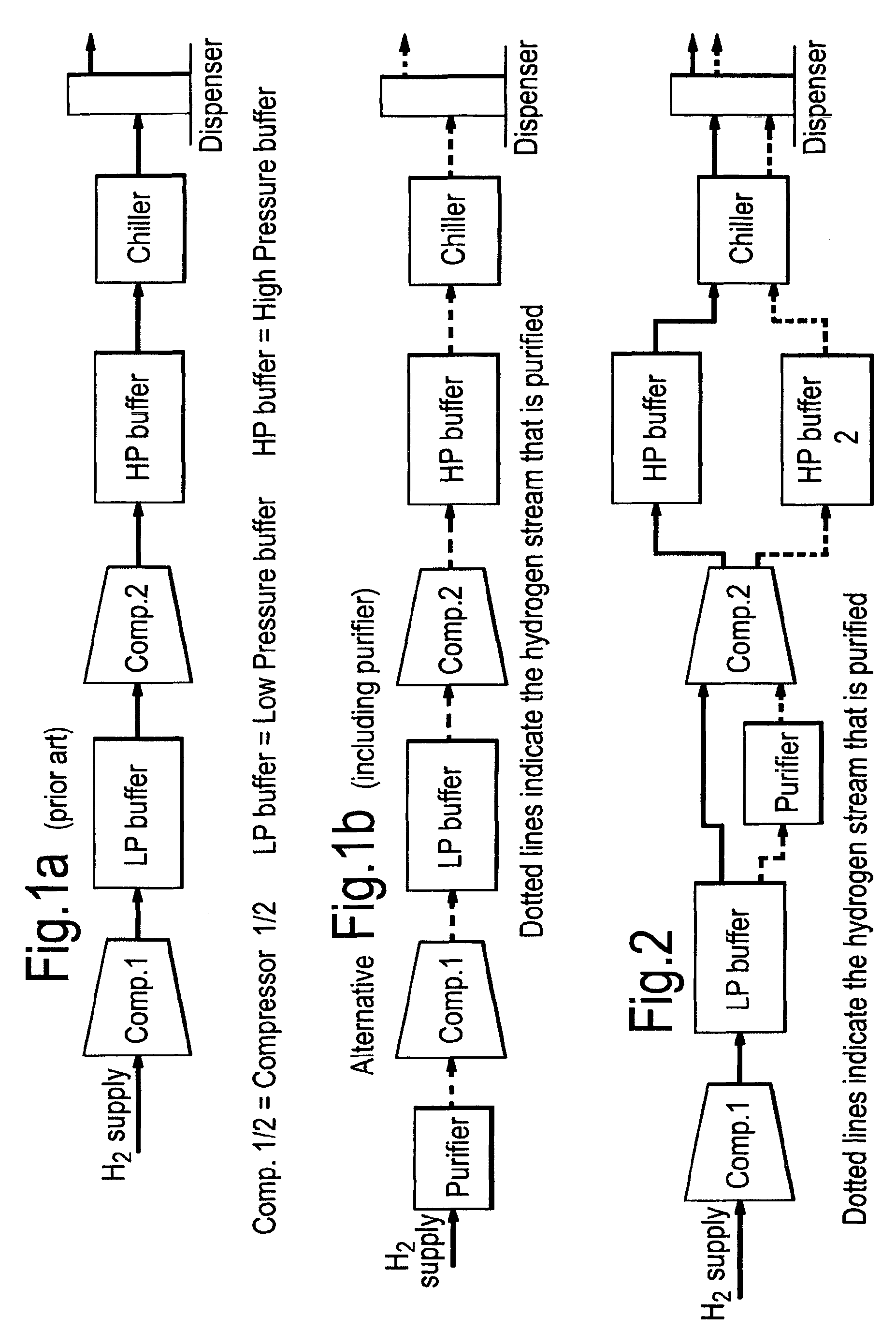
Figure 1a shows a simplified schematic diagram of the hydrogen flow at a refuelling
station according to the prior art. Hydrogen of industrial purity flows from the input,
possibly via a purifier (see Fig. 1b), (potentially via a compressor, Comp.1) to a
low pressure buffer tank (200-350bar), via a compressor (Comp.2) to a high pressure
tank (up to 700bar) and then through a chiller to the final dispenser. Details of
mass flows and options such as multiple dispensers and storage tanks are omitted for
the sake of simplicity.
Figure 2 provides a schematic representation of a system according to the invention
illustrating purification after the low pressure buffer tank.
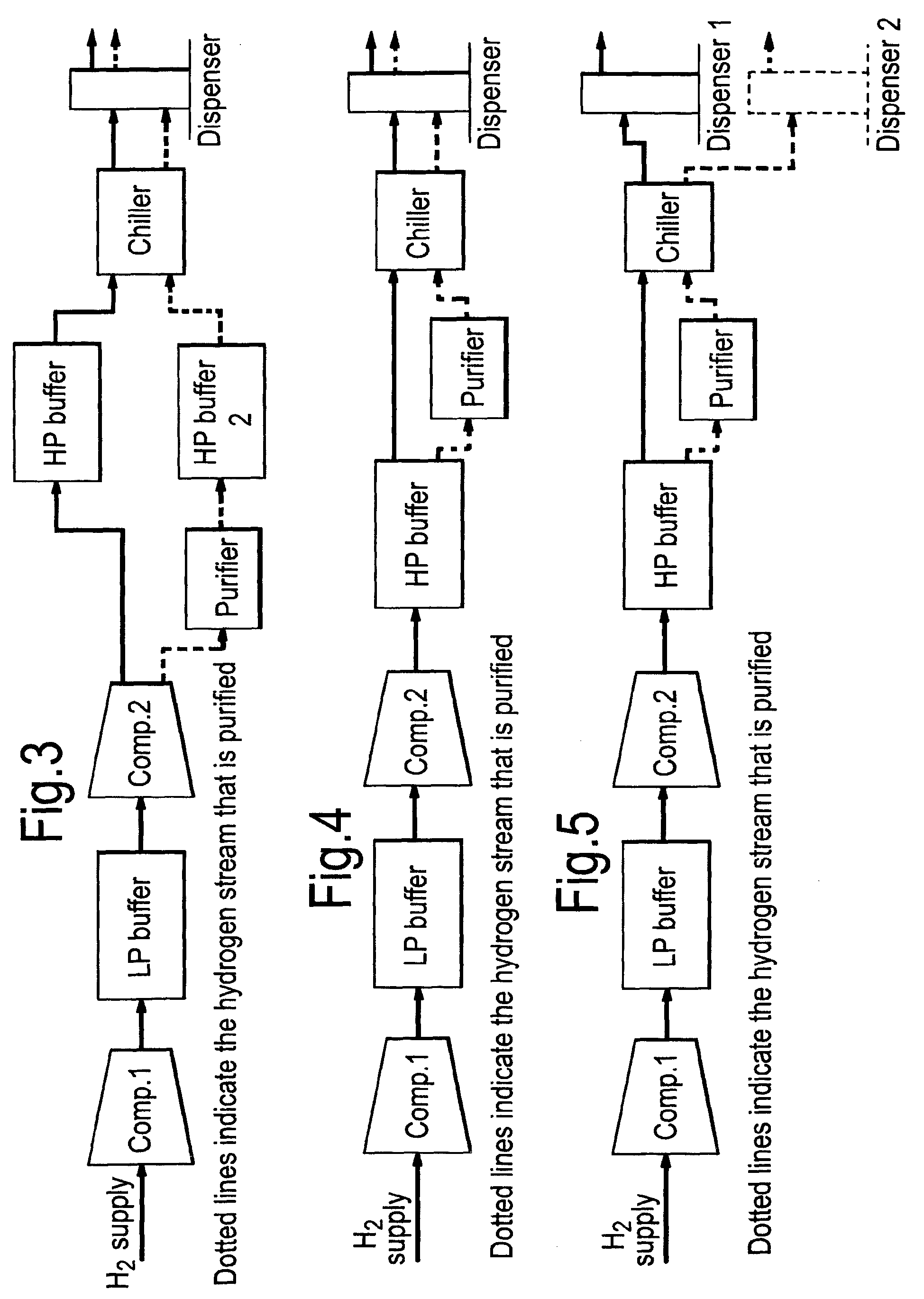
Figure 3 provides a schematic representation of a system according to the invention
illustrating purification after the compression step.
Figure 4 provides a schematic representation of a system according to the invention
illustrating purification between high pressure buffer and dispenser.
Figure 5 provides a schematic representation of a system according to the invention
illustrating dispensing of high-purity hydrogen from a dedicated unit (the location
of the purifier is not specific, may also be at different positions).
Detailed description of the invention
[0013] The invention described herein provides a process for dispensing gaseous hydrogen
in different qualities.
[0014] In a further embodiment of the invention, the process further comprising passing
the initial stream of hydrogen from a supply (potentially via a compressor), into
a low pressure buffer tank (200-350bar), subsequently passing the stream via a compressor
into a In a further embodiment of the invention, the process further comprising passing
the initial stream of hydrogen from a supply (potentially via a compressor), into
a low pressure buffer tank (200-350bar), subsequently passing the stream via a compressor
into a high pressure buffer tank (up to 700bar), followed by passing the stream via
a chiller to a final dispenser, wherein the process further comprises a step in which
a part of the hydrogen stream is separated and passed through a purifier which is
located in line after the low pressure tank.
[0015] In another embodiment of the invention, the part of the hydrogen that is separated
in the process, is passed through a purifier before it is compressed, preferably using
the same compressor as is used for compressing the remaining part of the hydrogen.
[0016] Preferably, a fraction of the initial hydrogen stream (delivered at a purity level
meeting the relevant standard) of below 50%, in an embodiment of below 25% and in
another embodimenmt of below 10% is taken from the bulk (low pressure) storage and
purified further. The pure stream is then compressed, preferably using the same compressor
as the rest of the hydrogen (but at a different time) and stored in a separate high
pressure buffer storage (Fig. 2). Preferably, the (second) compressor is designed
appropriately and run in such a way that it runs on a schedule which maintains both
buffer tanks full for as much of the time as possible, to make the best use of the
equipment. From the high pressure storage the purified hydrogen stream passes through
the same cooler and can be dispensed by the same dispenser as the main grade (remaining
hydrogen stream); the customer can select the quality at the dispenser.
[0017] Preferably, the purification is carried out as close as possible to the dispensing
point, i.e. after the (second) compression step. Thus, a further embodiment relates
to a process, wherein the stream of hydrogen is first passed through the compressor
and thereafter a part is separated for passing through a purifier. Preferably, the
separated part of hydrogen is subsequently led into a second high pressure buffer
tank followed by passing it into the same chiller as is used for chilling the remaining
part of the hydrogen (Fig. 3). In this process, it is highly preferred that chilling
of the separated part of the hydrogen takes place at a different time than that of
the remaining part of the hydrogen. Otherwise, the streams get mixed and only one
grade of hydrogen can be dispensed. Preferably, the system runs on a schedule which
maintains all buffer tanks full for as much of the time as possible.
[0018] Still closer to the dispensing point, the hydrogen stream may be separated and purified
at an even later stage. Thus, in another embodiment, the stream of hydrogen is first
passed through both the compressor and the high pressure buffer tank and thereafter
a part is separated for passing it through a purifier (Fig. 4).
[0019] In this process, it is highly preferred that chilling of the separated part of the
hydrogen takes place at a different time than that of the remaining part of the hydrogen.
Otherwise, the streams are mixed and only one grade of hydrogen can be dispensed.
Preferably, the system runs on a schedule which maintains all buffer tanks full for
as much of the time as possible.
[0020] In another embodiment of the invention, a separate dispenser is used for the purified
hydrogen (see Fig 5).
[0021] Purification of hydrogen according to the invention takes place using techniques
known in the art, and preferably, wherein the purification comprises use of a membrane
or a palladium catalyst.
1. A process for dispensing gaseous hydrogen at a refuelling station comprising before
dispensing dividing an initial hydrogen stream into at least two streams, wherein
at least one, but not all, of the streams is purified in a hydrogen purification step
or steps.
2. The process according to claim 1, further comprising passing the initial stream of
hydrogen from a supply into a low pressure buffer tank, subsequently passing the stream
via a compressor into a high pressure buffer tank, followed by passing the stream
via a chiller to a final dispenser, wherein the process further comprises a step in
which a part of the hydrogen stream is separated and passed through a purifier which
is located in line after the low pressure tank.
3. The process according to claim 2, wherein the part of the hydrogen that is separated
is passed through a purifier before it is compressed.
4. The process according to claim 3, wherein the hydrogen is compressed using the same
compressor as for compressing the remaining part of the hydrogen.
5. The process according to claim 4, wherein compression of the separated part of the
hydrogen takes place at a different time than that of the remaining part of the hydrogen.
6. The process according to claim 4 or 5, wherein the system runs on a schedule which
maintains the buffer tanks full for as much of the time as possible.
7. The process according to claim 2, wherein the stream of hydrogen is first passed through
the compressor and thereafter a part is separated for passing through a purifier.
8. The process according to claim 7, wherein the separated part of hydrogen is subsequently
led into a second high pressure buffer tank followed by passing it into the same chiller
as is used for chilling the remaining part of the hydrogen.
9. The process according to claim 8, wherein chilling of the separated part of the hydrogen
takes place at a different time than that of the remaining part of the hydrogen.
10. The process according to claim 8 or 9, wherein the system runs on a schedule which
maintains the buffer tanks full for as much of the time as possible.
11. The process according to claim 2, wherein the stream of hydrogen is first passed through
both the compressor and the high pressure buffer tank and thereafter a part is separated
for passing it through a purifier.
12. The process of claim 11, wherein the purification is followed by passing the separated
part into the same chiller as is used for chilling the remaining part of the hydrogen.
13. The process of any one of claims 1 to 12, wherein the purification comprises using
a membrane or a palladium catalyst.
14. The process of any one of claims 1 to 13, wherein a separate dispenser is used for
the purified hydrogen.
15. A system for dispensing gaseous hydrogen comprising in a subsequent line-up a combination
of the following: a low pressure buffer tank (LPB), a compressor (Comp.), a high pressure
buffer tank (HPB), a chiller (Ch.) and at least one final dispenser (disp.), wherein
at least one of LPB, Comp. and HPB has two exits, one for separating a part of the
hydrogen stream, the other for the remaining part of the hydrogen stream, and wherein
the system further comprises a purifier, the inlet of the purifier being located in
line after one exit of one of LPB, Comp. and HPB for the separated part of the hydrogen
stream.
1. Verfahren zum Ausgeben von gasförmigem Wasserstoff an einer Auftankstation, umfassend,
vor dem Ausgeben, das Teilen eines anfänglichen Wasserstoffstroms in mindestens zwei
Ströme, wobei mindestens einer, aber nicht alle, der Ströme in einem Wasserstoffreinigungsschritt
oder -schritten gereinigt werden.
2. Verfahren nach Anspruch 1, ferner umfassend das Durchleiten des anfänglichen Wasserstoffstroms
von einer Versorgung in einen Unterdruck-Puffertank, danach Durchleiten des Stroms
durch einen Verdichter in einen Hochdruck-Puffertank, danach Durchleiten des Stroms
durch einen Kühler zu einer abschließenden Ausgabevorrichtung, wobei das Verfahren
ferner einen Schritt umfasst, bei dem ein Teil des Wasserstoffstroms abgeschieden
wird und durch eine Reinigungsvorrichtung geleitet wird, die in einer Linie nach dem
Unterdrucktank angeordnet ist.
3. Verfahren nach Anspruch 2, wobei der Teil des Wasserstoffs, der abgeschieden wird,
durch einen Reiniger geleitet wird, bevor er verdichtet wird.
4. Verfahren nach Anspruch 3, wobei der Wasserstoff mithilfe des gleichen Verdichters
verdichtet wird, der auch zum Verdichten des restlichen Teils des Wasserstoffs verwendet
wird.
5. Verfahren nach Anspruch 4, wobei das Verdichten des abgeschiedenen Teils des Wasserstoffs
zu einem anderen Zeitpunkt stattfindet als das des restlichen Teils des Wasserstoffs.
6. Verfahren nach Anspruch 4 oder 5, wobei das System in einem Zeitplan läuft, der die
Puffertanks solange wie möglich voll hält.
7. Verfahren nach Anspruch 2, wobei der Wasserstoffstrom zuerst durch den Verdichter
geleitet wird und danach ein Teil zum Durchleiten durch eine Reinigungsvorrichtung
abgeschieden wird.
8. Verfahren nach Anspruch 7, wobei der abgeschiedene Teil des Wasserstoffs anschließend
in einen zweiten Hochdruck-Puffertank geleitet wird, wonach er durch die gleiche Kühlvorrichtung
geleitet wird, die auch zum Kühlen des restlichen Wasserstoffteils verwendet wird.
9. Verfahren nach Anspruch 8, wobei das Kühlen des abgeschiedenen Teils des Wasserstoffs
zu einem anderen Zeitpunkt stattfindet als das des restlichen Teils des Wasserstoffs.
10. Verfahren nach Anspruch 8 oder 9, wobei das System in einem Zeitplan läuft, der die
Puffertanks solange wie möglich voll hält.
11. Verfahren nach Anspruch 2, wobei der Wasserstoffstrom zuerst durch den Verdichter
und den Hochdruck-Puffertank geleitet wird und danach ein Teil zum Durchleiten davon
durch eine Reinigungsvorrichtung abgeschieden wird.
12. Verfahren nach Anspruch 11, wobei nach der Reinigung der abgeschiedene Teil durch
die gleiche Kühlvorrichtung geleitet wird, die auch zum Kühlen des restlichen Teils
des Wasserstoffs verwendet wird.
13. Verfahren nach einem der Ansprüche 1 bis 12, wobei die Reinigung das Verwenden einer
Membran oder eines Palladiumkatalysators umfasst.
14. Verfahren nach einem der Ansprüche 1 bis 13, wobei eine separate Ausgabevorrichtung
für den gereinigten Wasserstoff verwendet wird.
15. System zum Ausgeben von gasförmigem Wasserstoff, umfassend in einer nachfolgenden
Aufstellung eine Kombination aus Folgendem: Niederdruck-Puffertank (LPB), Verdichter
(Comp.), Hochdruck-Puffertank (HPB), Kühlvorrichtung (Ch.) und mindestens eine abschließende
Abgabevorrichtung (Disp.), wobei mindestens eines von LPB, Comp. und HPB zwei Ausgänge
aufweist, einen zum Abscheiden eines Teils des Wasserstoffstroms und den anderen für
den restlichen Teil des Wasserstoffstroms, und wobei das System ferner eine Reinigungsvorrichtung
umfasst, wobei der Eingang der Reinigungsvorrichtung in Linie nach einem Ausgang eines
von LPB, Comp. und HPB für den abgeschiedenen Teil des Wasserstoffstroms angeordnet
ist.
1. Procédé de distribution d'hydrogène gazeux dans une station de ravitaillement comprenant,
avant la distribution, la division d'un courant d'hydrogène initial en au moins deux
courants, au moins un des courants, mais pas tous, étant purifié dans une étape ou
des étapes de purification d'hydrogène.
2. Procédé selon la revendication 1, comprenant en outre l'acheminement du courant initial
d'hydrogène d'une réserve à l'intérieur d'un réservoir tampon à basse pression, l'acheminement
successif du courant via un compresseur à l'intérieur d'un réservoir tampon à haute
pression, suivi de l'acheminement du courant via un refroidisseur jusqu'à un distributeur
final, le procédé comprenant en outre une étape dans laquelle une partie du courant
d'hydrogène est séparée et acheminée à travers un purificateur qui est situé en ligne
après le réservoir à basse pression.
3. Procédé selon la revendication 2, dans lequel la partie de l'hydrogène qui est séparée
est acheminée à travers un purificateur avant d'être comprimée.
4. Procédé selon la revendication 3, dans lequel l'hydrogène est comprimé en utilisant
le même compresseur que pour comprimer la partie restante de l'hydrogène.
5. Procédé selon la revendication 4, dans lequel la compression de la partie séparée
de l'hydrogène a lieu à un moment différent de celle de la partie restante de l'hydrogène.
6. Procédé selon la revendication 4 ou 5, dans lequel le système fonctionne suivant un
programme qui maintient les réservoirs tampons pleins aussi longtemps que possible.
7. Procédé selon la revendication 2, dans lequel le courant d'hydrogène est d'abord acheminé
à travers le compresseur puis une partie est séparée pour être acheminée à travers
un purificateur.
8. Procédé selon la revendication 7, dans lequel la partie séparée d'hydrogène est ensuite
conduite dans un deuxième réservoir tampon à haute pression puis est acheminée dans
le même refroidisseur que celui utilisé pour refroidir la partie restante de l'hydrogène.
9. Procédé selon la revendication 8, dans lequel le refroidissement de la partie séparée
de l'hydrogène a lieu à un moment différent de celui de la partie restante de l'hydrogène.
10. Procédé selon la revendication 8 ou 9, dans lequel le système fonctionne suivant un
programme qui maintient les réservoirs tampons pleins aussi longtemps que possible.
11. Procédé selon la revendication 2, dans lequel le courant d'hydrogène est d'abord acheminé
à la fois à travers le compresseur et le réservoir tampon à haute pression et ensuite
une partie est séparée pour être acheminée à travers un purificateur.
12. Procédé de la revendication 11, dans lequel la purification est suivie de l'acheminement
de la partie séparée dans le même refroidisseur que celui utilisé pour refroidir la
partie restante de l'hydrogène.
13. Procédé de l'une quelconque des revendications 1 à 12, dans lequel la purification
comprend l'utilisation d'une membrane ou d'un catalyseur au palladium.
14. Procédé de l'une quelconque des revendications 1 à 13, dans lequel un distributeur
séparé est utilisé pour l'hydrogène purifié.
15. Système de distribution d'hydrogène gazeux comprenant dans un alignement successif
une combinaison des éléments suivants : un réservoir tampon à basse pression (LPB),
un compresseur (Comp.), un réservoir tampon à haute pression (HPB), un refroidisseur
(Ch.) et au moins un distributeur final (disp.), au moins un des éléments LPB, Comp.
et HPB ayant deux sorties, une pour séparer une partie du courant d'hydrogène, l'autre
pour la partie restante du courant d'hydrogène, et le système comprenant en outre
un purificateur, l'entrée du purificateur étant située en ligne après une sortie d'un
des éléments LPB, Comp. et HPB pour la partie séparée du courant d'hydrogène.
REFERENCES CITED IN THE DESCRIPTION
This list of references cited by the applicant is for the reader's convenience only.
It does not form part of the European patent document. Even though great care has
been taken in compiling the references, errors or omissions cannot be excluded and
the EPO disclaims all liability in this regard.
Patent documents cited in the description