|
(11) | EP 3 491 368 B1 |

| (12) | EUROPEAN PATENT SPECIFICATION |
|
|
| (54) |
METHOD TO RADIOGRAPHICALLY DETERMINE GEOMETRICAL PARAMETERS AND/OR SUBSTANCE STATE OF AN OBJECT UNDER STUDY VERFAHREN ZUR RADIOGRAPHISCHEN BESTIMMUNG GEOMETRISCHER PARAMETER UND/ODER DES SUBSTANZZUSTANDS EINES UNTERSUCHTEN OBJEKTS PROCÉDÉ DE DÉTERMINATION RADIOGRAPHIQUE DE PARAMÈTRES GÉOMÉTRIQUES ET/OU D'ÉTAT DE SUBSTANCE D'UN OBJET À L'ÉTUDE |
|
|
|||||||||||||||||||||||||||||||
| Note: Within nine months from the publication of the mention of the grant of the European patent, any person may give notice to the European Patent Office of opposition to the European patent granted. Notice of opposition shall be filed in a written reasoned statement. It shall not be deemed to have been filed until the opposition fee has been paid. (Art. 99(1) European Patent Convention). |
[0001] The present invention relates to a method by means of which an object can be displayed (for diagnostic purposes, e.g. structural inspections) in a radiation receiving device via the object being irradiated from a point of projection by radiation emitted by a - quasi - point-like radiation source serving as the source of radiation, particularly, of X- and/or gamma rays, wherein the object has well-defined geometrical and radiation physical characteristics, here e.g. X- and/or gamma ray absorption properties, and wherein the radiation receiving device (provided, in particular, as a film and/or any other suitable detecting means) shows, at a certain resolution, a change proportional to the amount of radiation incident onto and absorbed by the radiation receiving device in its pixels (i.e. in surface portions of a given size of the device) that actually represent the units of resolution used. Based on the change, i.e. by means of evaluating the change, geometrical parameters and/or the material state of the object under study may be determined.
[0002] In industry, ultrasonic or screening (radiographic) imaging techniques are used by choice for non-destructive inspection (corrosion/erosion) of various constructional parts, especially hollow objects, such as e.g. pipes, conduits, as well as weld seams thereof. In particular, in the field of e.g. (nuclear) power industry, ultrasonic wall thickness measurements are used to inspect (a) the pipe bends (especially, the outer bends), (b) the "T" members of the pipe connections and (c) the reducing/expanding pieces and further fitting elements in the case of pipes/conduits used in a power station.
[0003] Ultrasonic testings are impractical for the in-situ inspection of duplicated constructions (e.g. pipe-in-pipe structures) during operation of the plant, and optionally without removing heat insulation.
[0004] In the so-called radiographic tangential imaging technique (see below), which is known in the field of radiographic imaging, but not spread in practice, as a consequence of the nature of the radiation source used, empty pipes having a diameter of up to about 300 mm are imaged onto a film/detector, and then the wall-shadow of the pipe is assessed. The technique is applicable for pipes with a wall thickness of up to about 10 to 15 mm.
[0005] The industrial application of computer tomography (CT) is also known, however, in real industrial practice, i.e. not under laboratory conditions, CT is unaccomplishable. (Here, the relative position of the radiation source and the film/detector is fixed, but it is on the move relative to the object under study.)
[0006] It is of also importance that, in ultrasonic wall thickness measurements, the inspected material's surface is extremely small compared to a material's surface that can be displayed on a film/detector and inspected by radiography.
[0007] A radiographic tangential imaging technique, wherein reference elements are also imaged onto the film/detector simultaneously with the inspected object is also known. Thus, when the image is assessed, the image of one or more reference element is also available together with the image of the object. In such a case, thickness data of the inspected object can simply be derived in correlation with the images of the reference elements. Such a solution is disclosed e.g. in HU Patent No. 187,820 and EP Patent No. 128,922 B1 to determine the condition of pipes/conduits during operation of the plant.
[0008] The application of said reference elements makes a radiographic tangential imaging process more complicated, and will also largely reduce the area of the film/detector useful from the point of view of the imaging. Thus, in turn, it decreases the thickness of object that can be studied by the process.
[0009] The paper by A. Hecht et al. published electronically in NDT.net (see http://www.ndt.net/article/ecndt98/chemical/101/101.htm; October 1998, Vol.3,No.10) under the title "On-Line Radiographic Wallthickness-Measurement of Insulated Piping in the Chemical and Petrochemical Industry" teaches a radiographic tangential imaging method suitable for measuring the wall thickness of an industrial conduit which uses a flat surface electronic gamma- and/or X-ray detector to take the radiographic image of the conduit under study and a computerized digital data processing to evaluate the radiographs. Wall thickness of the conduit is determined on the basis of a projected digital image of the conduit wall, i.e. the "wall-shadow", by means of exploiting the geometrical relations characteristic of the geometrical arrangement that has been used to take the image. Accordingly, the method can only be used if the flat surface of the detector is capable of receiving/displaying a projected (and, hence, magnified, too) full image of the inspected conduit taken along the diameter of said conduit.
[0010] The paper by B. Redmer et al. published electronically in NDT.net (see http://www.ndt.net/article/ecndt02/308/308.htm; December 2002, Vol. 7, No.12) under the title "Mechanised Weld Inspection by Tomographic Computer Aided Radiometry (TomoCAR)" discloses a method and a system for a computer assisted study of industrial conduits by radiometric scan, wherein a combined unit of a radiation source/detector is used that runs round the outer surface of the conduit under inspection line by line. Thickness of the wall is determined from the obtained digital data by means of laminographic and/or plain tomographic image reconstruction techniques. The method is rather complicated and, thus, expensive.
[0011] According to the prior art, the wall thickness measurement based on radiographic imaging is known, however, the pipe diameter to be handled by this technique - as discussed above - is rather limited. In this regard, the reader is referred to a contribution by GE Sensing & Inspection Technologies under the title "Computed Radiography Plus Rhythm Software Platform for FAC (Flow Accelerated Corrosion) Inspection in Nuclear Secondary Circuit" (for further details, see the conference proceedings of the 8th International Conference on NDE in Relation to Structural Integrity for Nuclear and Pressurized Components - We.3.B.3 held in Berlin, Germany between 29 September and 1 October 2010) as the most complete summary of the respective prior art.
[0012] Each - prior art - document cited above discloses a (tangential) projected-imaging film/detector arrangement to be used with pipes of about 220 to 250 mm in diameter and 15 mm in wall thickness, wherein the inspected pipes may also provided with heat insulation.
[0013] Moreover, each method discussed above performs measurements of the magnified projection of the wall thickness of the pipe under study appearing on the film/detector, naturally, through recalculating the extent of magnification. A solution combined with a reference calibration test piece also exists.
[0014] Nevertheless, the methods discussed have fundamental limitations since imaging the wall thickness of a conduit at the outer surface of said conduit results a material thickness of zero, while the largest material thickness that could be imaged at the inner surface cannot be displayed in most cases. This problem is illustrated in Figures 2d, 2c. Its core lies in the fact that in the methods according to the prior art, surely, the inner surface of the conduit is not located, in the concrete, at the position where it actually appears to be on the film/detector, but closer to the outer surface. Accordingly, the wall thickness determination is not accurate. As the pipe diameter and the wall thickness of the pipe increase, the problem gets even worse. Among other things, this is the reason for the methods disclosed above being not suitable to measure the wall thickness of a conduit of large diameter (greater than 250 mm in its outer diameter).
[0015] Thus, the object of the present invention is to eliminate or at least to alleviate the problems arising in the respective prior art techniques, and in parallel with this, to provide an alternative non-destructive inspection technique based on radiography to determine the geometrical parameters and/or the material state of an hollow body, and preferably a tubular object to be inspected.
[0016] A further object of the present invention is to provide a non-destructive diagnostic technique based on radiography that can be used to inspect reliably, e.g. for diagnostic purposes, a conduit of an arbitrary outer diameter and wall thickness during or out of operation and, optionally, provided with an outer heat insulation layer as well. Apparently, hardness (energy) of the scanning radiation obtainable by the source of radiation used to prepare the projected radiographic image presents a fundamental limit to the largest measurable material thickness of the conduit wall.
[0017] A yet further object of the present invention is to provide such a non-destructive inspection method based on radiography, wherein to ensure evaluability of the measurement, there is no need to use a reference calibration test piece when the imaging is performed.
[0018] In case of the inventive solution - in accordance with claim 1 - no reference calibration test pieces are required to determine the thickness/wall thickness parameter of an object, particularly a hollow body, and preferably a tubular object under inspection, and the detectable pipe diameter is not limited. Furthermore, the radiation receiving device used for the imaging can equally have a flat surface or an incurvated surface of cylindrical shell shape, as is shown in Figures 1a to 1d and Figures 6a, 6b. The inventive technique does not require imaging the wall thickness of the tubular object under study and, thus, recording the wall-shadow (however, the latter is possible). Instead, the method according to the present invention is to determine the so-called remarkable points of the tubular object in/on the object and the respective projected positions of said remarkable points on the radiation receiving device used for the imaging.
[0020] In industrial practice, the present invention is suitable for measuring wall thickness of mainly pipes, conduits and/or assessing (preferably corrosion/erosion) states thereof (e.g. deposits, wearing, etc.). Application of the invention also allows performing inspections in (nuclear) power plants, or in the oil and chemical industry during operation, i.e. in situ, and even when the conduit inspected is provided with a continuous insulation layer.
[0021] When the inventive method is performed, that is, in the period of time for image display, the radiation source, the object to be inspected and the radiation receiving device itself, i.e. the film, detector, or any other means suitable for image pick-up/recording are all in a geometrically stable position relative to each other, or alternatively, any image defect due to the movement (e.g. vibration) thereof can be measured and thus eliminated.
[0022] In particular, a requisite for the non-destructive inspection method according to the invention is that the object to be inspected and arranged within the region irradiated by X- and/or gamma-rays, the device for receiving the radiation (that partially passes through the object), i.e. the film, detector, or any other means suitable for image pick-up/recording, and the radiation source itself have got geometrical and radiation physical parameters that can be expressed mathematically, and the object to be inspected, the radiation receiving device and the source of radiation are in a stable/non-moving position - within acceptable tolerance - for a period of time that is required to generate the radiograph, i.e. to create the image of the object by means of transillumination. Consequently, a line drawn from the source of radiation to any surface point of the radiation receiving device, i.e. the path of a given ray that passes through the object inspected can be interpreted from the point of view of dosimetry, and thus the intercept line passing through the object under inspection can be determined.
[0023] Basically, each of such intercept lines defines a single pixel on the radiation receiving device; here the term "pixel" refers to the smallest surface portion of the radiation receiving device that could be still observed as a separate surface element (that is, which carries information about the inspected object) at the highest possible resolution of the radiation receiving device. In particular, if the radiation receiving device is provided e.g. as a (traditional) X-ray film, a lower limit of the pixel dimension (i.e. the image resolution of industrial X-ray films) is about 0.05 mm on the minimum and, hence, the pixel size is 0.05 mm x 0.05 mm; at the resolution of e.g. 0.1 mm, 100 pixels can be defined over 1 mm2. That is, there are 12x106 (i.e. 12M) pixels present altogether on the surface of a film/detector with the size of 300x400 mm (120000 mm2); each of these pixels can be evaluated separately, i.e. carries information. The pixel size is increased by unsharpness that is partially of geometrical origin (it results from the fact that the radiation source itself is not a point-like source, e.g. an Ir-192 source has the size of about 2.0 mm x 3.0 mm), being present as external (geometrical) unsharpness, and partially originates from the unsharpness characteristic of the X-ray film itself (film unsharpness). Moreover, said unsharpness is also a function of the radiation energy that has primarily influence on the detectable value of the material thickness.
[0024] The extent of said film unsharpness depending on the radiation energy (and thus the type of radiation source) is summarized in Table 1 below.
Table 1.
| 100 keV (X-rays) | 0.05 mm |
| 200 keV | 0.10 mm |
| 400 keV | 0.15 mm |
| Ir-192 (gamma) | 0.17 mm |
| Co-60 | 0.35 mm |
| 2 MeV (linear accelerator) | 0.32 mm |
[0025] Data given above do not mean that smaller values cannot be observed, detected in arrangements characterized by the given energy values. Rather, they should be considered as representing characteristic values for the image resolution. As image quality indicators, for objects - of e.g. tubular shape - to be inspected, the so-called wire type IQI ("Image Quality Indicator") calibration test piece is suggested (for further details the reader is referred to the professional booklet edited and published by Agfa-Gevaert N.V. under the title "Industrial radiography") as this interferes with the image to the least extent. The IQI calibration test piece is a calibration test piece consisting of wires of various diameters arranged in accordance with standard order. When tubes are welded, said wires are, in general, placed in positions at right angle to the weld seam. However, in radiographic inspections, this arrangement is not applicable as for tubes with smaller diameter, a wire of the IQI calibration test piece lies on an intercept that goes through material changing in thickness and, thus, it may adversely influence the evaluation scheme used to determine the wall thickness. Hence, it is better if the calibration test piece is arranged at the nominal material thickness in parallel with the weld seam.
[0026] It is preferred if the wire diameter expectable in accordance with visibility is expressed as a percentage (%) of the nominal material thickness. Based on experience, if image enhancing devices used in the evaluation of radiographs, i.e. filtering means used to diminish the effects of scattered radiation are applied, this value may be 1.0%. According to the state of the art, the value of 0.5% is still possible.
[0027] In radiographic investigations, a yet further important feature is the contrast of the image, the relation of which with blackening ("density") is summarized in Table 2 below.
Table 2.
| density | contrast |
| 3.0 | 100% |
| 2.5 | 85% |
| 2.0 | 71% |
| 1.5 | 54% |
| 1.0 | 35% |
[0028] Based on experience, dose (≈ density) range of a film/detector to be used as the radiation receiving device can be evaluated within the range of 0.5 to 4.5, wherein the dose ratio is defined as the logarithm to base 10 of the ratio of the reference dose and the measured dose. In case of films, there exists a so-called blue-base (noise range of the evaluation) at the density of 0.2 to 0.25, this range can be avoided by means of using a slight margin.
[0029] Two types of single use film are recommended as radiation receiving device: the films with lead (Pb) intensification prepared and sold by the firms Agfa-Gevaert and Fuji (Japan). Table 3 below summarizes how the two different types of film can be made correspondent to each other.
Table 3.
| Agfa | Pb | Fuji | Pb | |
| D4 | = | 50 | ||
| D5 | = | 80 | ||
| D7 | = | 100 | ||
| D8 | = | 150 |
[0030] For larger material thicknesses, only radiation sources emitting gamma-rays are applicable. For example, for an Ir-192 source, the largest material thickness that can be transilluminated is about 4 inches (101.60 mm), which means that no X-rays at all are applicable at this and larger material thicknesses. For a Co-60 source (≈1.25 MeV), the detectable largest material thickness will be 8 inches (203.20 mm). For some elements, the most important material parameters - calculated at the energy of 1.0 MeV - are summarized in Table 4 below; here, in Table 4, column (I) contains the symbol and the atomic number of the respective element, column (II) contains the density ρ (by volume) of the element, columns (III) and (IV) contain the total attenuation coefficient µ and the linear attenuation coefficient µ∗ρ, column (V) is the absorption half-value thickness (HVT) of the respective element expressed in units of cm (here, the relation In 2 = 0.69315/µ∗ρ holds), while column (VI) contains the surface density of the respective element expressed in units of g/cm2.
Table 4.
| I | II | III | IV | V | VI |
| 13 Al | 2.70 | 0.06143 | 0.16586 | 4.1791 | 11.2836 |
| 14 Si | 2.34 | 0.06354 | 0.14868 | 4.6620 | 10.9091 |
| 22 Ti | 4.50 | 0.05875 | 0.26437 | 2.6219 | 11.7985 |
| 23 V | 6.10 | 0.05779 | 0.35252 | 1.9663 | 11.9942 |
| 24 Cr | 7.10 | 0.05912 | 0.41975 | 1.6513 | 11.7245 |
| 25 Mn | 7.40 | 0.05833 | 0.43164 | 1.6058 | 11.8833 |
| 26 Fe | 7.87 | 0.05975 | 0.46354 | 1.4953 | 11.7683 |
| 27 Co | 8.90 | 0.05890 | 0.52421 | 1.3223 | 11.7682 |
| 28 Ni | 8.90 | 0.06140 | 0.54646 | 1.2684 | 11.2891 |
| 29 Cu | 8.96 | 0.05881 | 0.52694 | 1.3154 | 11.7862 |
| 41 Nb | 8.57 | 0.05834 | 0.49997 | 1.3864 | 11.8813 |
| 42 Mo | 10.22 | 0.05809 | 0.59368 | 1.1675 | 11.9323 |
| 74 W | 19.30 | 0.06488 | 1.25218 | 0.5535 | 10.6836 |
| 82 Pb | 11.35 | 0.06971 | 0.79121 | 0.8760 | 9.9433 |
| water: | 1.00 | 0.07060 | 0.07060 | 9.8180 | 9.8180 |
[0031] It should be here noted that iron (Fe) actually stands for simple unalloyed carbon steels, while in industry in most cases alloyed steels are used; hence, the value of half-value thickness HVT has to be always checked. The above table shows possible alloying elements of steel, but element 82Pb. Table 4 is based on the document Health Physics Resources - UCRL - 501741: Compilation of X-Ray Cross Sections.
[0032] Knowledge and applications of the state of the art form indispensable parts of the method according to the invention. Radiography is part of non-destructing material testing (NDT). Therefore, international regulations and standards apply for the image analysis and evaluation. In this respect, the basic European standards are ISO 14096-1:2005(EN) and ISO 14096-2:2005(EN). Consequently, for films, for the time being, the apparatuses GE film digitizer FS50 and FS50B can (only) be offered. Some characteristic features of digitizer FS50B are as follow: maximum width of the analysed film may be 355 mm (14 inches); the minimum resolution is 0.05 mm, that is, the smallest pixel is of the size 0.05 mm x 0.05 mm; here, the density range is 0.05 to 4.7 D; density contrast sensibility: 0.02.
[0033] For diagnostic purposes, in case of e.g. an Ir-192 radiation source, the expected minimum pixel size is 0.1 mm x 0.1 mm; however, in case of a Co-60 radiation source, a pixel size of 0.2 mm x 0.2 mm is already acceptable/allowable.
[0034] It should be here also noted that, for diagnostic purposes (such as e.g. the inspection of weld seams), films D4, D5 in Table 3 can be considered to be suitable, however, for tube wall thickness measurements, that forms a possible aspect of the invention, film D8 is sufficient (in case of e.g. an Ir-192 radiation source, the exposure time of film D8 compared to that of film D5 is about 30%). It is also noted here that wall thickness measurements of pipes and conduits are performed nowadays by ultrasonic testing. In light of this, we presume that a pixel size of 0.25 mm x 0.25 mm or 0.20 mm x 0.20 mm is perfectly suitable for the wall thickness measurements of pipes and conduits. These data also take into account the geometrical unsharpness that arises due to the dimension and shape of the radiation source. If the above criteria are accepted, X-ray films can be replaced by a "flat panel" of the type DXR-250C-W and/or DXR25U-W (manufacturer: General Electric, Inc., USA) when the inventive method is performed. (Here, there is only a size difference present between the two types of panel, that is, the panel denoted by C is 8" by 8" in size, while the other one denoted by U is 16" by 16" in size.) As said apparatuses are also GE products, they can be operated with the software platform of digitizer FS50B. Moreover, the detectors in the panels are flat surface detectors and are not bendable, the detecting substance therein is gadolinium oxy-sulphide (GOS), and the pixel size is 0.2 mm x 0.2 mm.
[0035] It is clear that these detectors are not suitable for diagnostic purposes, however, within the framework of the present invention they can be used to replace traditional films as the radiation receiving device. The exposure time of GOS detectors is commensurate to that of so-called RCF films, which is about 20% to 30% of the exposure time of film D8 cited above.
[0036] If it is taken into account that a blackening of smaller extent (2.0 or even a yet smaller value instead of 2.5) is enough to perform wall thickness measurements, the exposure times required to take the individual tangential radiographs can be decreased. As far as the films are concerned, so-called "phosphor" films - wherein AgBr2 is substituted with phosphorous compounds - would be highly preferred in this regard, however, they are incompatible with the digitizer FS50B.
[0037] For example, in case of an active insulated steam conduit in operation having a tube diameter of 465 mm, with insulation 770 mm, and having a tube wall thickness of 16 mm, assuming an operation temperature of 270°C and a steam pressure of 46 bar, the total dosimetry wall thickness will be 40 mm (total tube wall thickness is 32 mm + contribution of heat insulation material is 1 mm + iron-equivalent wall thickness of steam is 7 mm). At focus-to-film distance of 770 mm with the application of an Ir-192 radiation source, the activity of which is 850 GBq, the exposure time required to achieve a density of 2.5 for the various radiation receiving devices changes as follows:
- film Fuji 80+Pb: exposure time is 50 min;
- film D8: exposure time is 15 min;
- film RCF: exposure time is 5 min.
[0038] Under the same conditions, but requiring a density of 2.0, the exposure time decreases further, e.g. it will be 12 min and 4 min for the films D8 and RCF, respectively. In case of a flat panel, the exposure time can even be shorter.
[0039] In the above exemplary inspection, the following problem arises: in case of an "empty" conduit, the exposure would take place for a double wall thickness (2S = 32.0 mm). If this was imaged to a film, based on the geometrical data of the steam conduit, the material thickness corresponding to 2S would be located in the conduit wall at a distance of 0.56 mm from the outer surface towards the inside of the conduit. The greatest material thickness (that is, 169.5 mm) appears at the intercept that belongs to the inner surface of the conduit wall, said greatest material thickness attenuates the dose of irradiation by a rate of about 1/10000, and thus - as is shown in Figures 2c and 2d - it results in a broad bright band over the film/detector. As a consequence, it is rather difficult to determine the intercept belonging to the inner surface. For an inspection to be performed in the operating state of the conduit (i.e. there is steam in the conduit), the situation would be much worse.
[0040] The invention is now explained in more detail with reference to the accompanying drawings, wherein
- Figures 1a, 1b, 1c and 1d illustrate the arrangement of a tube to be inspected and a radiation receiving device, preferably a film, in case of a radiation receiving device with flat surface (Figures 1a and 1b; tangential radiographic imaging) and in case of a radiation receiving device that follows the curvature of the tube shell (Figures 1c and 1d), without an insulation coating (Figures 1a and 1c) and with a continuous insulation coating (Figures 1a and 1d);
- Figures 2a, 2b, 2c and 2d are a cross sectional view of the arrangement shown in Figure 1a with an intercept curve, a longitudinal sectional view of the arrangement shown in Figure 1a with the plane of intercept, a top sectional view of the arrangement shown in Figure 1a with the film, and the characteristic curve (or film density) obtained by evaluating the exposed film that corresponds to the intercept curve shown in Figure 1a, respectively;
- Figure 3 represents a dedicated case, wherein the inner diameter of the tube and the outer diameter of the tube go through different centres, that is, the tube under inspection is an eccentric tube and, hence, the tube wall thickness is not uniform in sections taken perpendicular to the longitudinal axis of the tube;
- Figure 4 illustrates the basis of the inventive technique;
- Figures 5a, 5b and 5c show in the cross sectional, longitudinal sectional and top sectional views, respectively, of the tube how to interpret a defect (e.g. a void) in the tube wall and to determine its location; and finally
- Figures 6a and 6b illustrate traditional film/radiation source arrangements used in nowadays practice for inspections in non-operating states with a film arranged on the inner cylindrical surface and the outer cylindrical surface, respectively, of a tube; it is important, that in this case radiation travels through a material of only a single wall thickness.
[0041] Tubes illustrated in Figures 1, 2 and 5 are of identical size; furthermore, tubes shown in Figures 3, 4 and 6 are of also identical size. The drawings are approximately scaled drawings. Referring now to Figures 1 to 6, reference signals used in the drawings are explained in Table 5 below.
Table 5.
| 100 | radiation used for imaging (X- and/or γ-radiation) |
| 200 | tube |
| 300 | insulation layer |
| 400 | radiation receiving device (in particular, any of a film, a detector, an imaging device) sensitive to radiation used for imaging |
| γ | source of radiation or, alternatively, point of projection |
| F*F=FF | distance between the radiation receiving device and the source of radiation, reference distance for the exposure |
| FFΔ | actual distance between the radiation receiving device and the source of radiation |
| FFr | distance between the radiation receiving device and the source of radiation measured from the point of projection along a given direction |
| A | intercepts belonging to the tube 200 in parallel projection |
| B | intercepts belonging to the tube 200 when projected from a projection point corresponding to the source γ of radiation |
| Q | (general) centre of the tube 200 |
| Q1, Q2 | centres of an eccentric tube 200 (see Figure 3) |
| S | (general) wall thickness of the tube 200 |
| Sn | magnified projection image of the wall thickness S on the radiation receiving device 400 in harmony with Figure 4 |
| SΔ | intercept belonging to the wall thickness S |
| 2S | (general) intercept belonging to the twice of the wall thickness S of the tube 200 |
| M1 | longest intercept belonging to the tube in parallel projection |
| M2 | longest intercept belonging to the tube when projected from a projection point that corresponds to the source γ of radiation |
| M3 | longest intercept belonging to the tube with centres Q1, Q2 when projected from a projection point that corresponds to the source γ of radiation |
| M4 | (general) the tube 200 contains a filling substance (e.g. water, steam, etc.) |
| M5 | (general) the tube is a full tube, i.e. it forms a bar, cylinder; its diameter D is shown in Figure 4 |
| M6 | diameter d of a hollow tube as shown in Figure 4, the relation ØD - Ød = 2S holds |
| x, y, z | axes of reference |
| Xm0, Xm1 | projections of the intercepts belonging to the tube 200 along axis x of a flat surface radiation receiving device 400 in harmony with Figure 2 |
| Xm2, Xm3 | projections of the intercepts belonging to the tube 200 along axis x of a flat surface radiation receiving device 400 in harmony with Figure 2 |
| G, H, I, J | four corners of the radiation receiving device 400 |
| GH; JI | sections parallel with axis z |
| GJ; HI | sections parallel with axis x |
| C | defect (e.g. a void) within the wall of the tube 200 as shown in Figure 5 |
| Cn | magnified projected image of defect C on the radiation receiving device 400 as illustrated in Figure 5 |
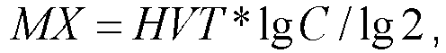
| MX | (general) material thickness obtained from an intercept |
[0042] In what follows, we explain in brief how the material thickness MX can be obtained from the nominal exposure data.
[0043] Knowing the density (characteristic) curve of the radiation receiving device 400 - for the sake of simplicity, from now on, the film/detector - it can be accepted that density of the film/detector is proportional to the dose of irradiation (DF), and the relation
holds on the basis of the applied parameters.
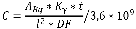
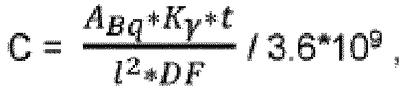
[0044] Each term in the base equation for exposure can be determined separately, for example it holds that
wherein
- t
- = exposure time (in units of second),
- DF
- = dose (in units of Sv),
- I
- = (focus-to-pixel) distance (in units of meter),
- HVT
- = half-value thickness (in units of meter),
- ABq
- = activity (in units of Bq),
- Kγ
- = dose coefficient (mSv.m2/GBq.h)
- MX
- = material thickness belonging to the intercept.
[0045] From equation (2), after its transposal, one obtains that
or
Now, if the right side of equation (3) is denoted by C, one obtains the relation of
from which
Using the latter, the intercept in the material can be expressed as
The traditional interpretation is shown in Figure 4: intercepts in hemi-space A and hemi-space B can be easily compared (here, the term "intercept" refers to the distribution of material between the source y of radiation and a pixel point obtained by the tangential radiographic imaging performed with the source y of radiation). Figure 4 shows the positions of the remarkable intercepts, i.e. 2S, M1, M2, all the intercepts are located in the XY plane. Essentially, the envelope of the intercept lines, or rather the so-called intercept curve, is uniquely defined by the position of the point of projection (source y of radiation). This situation is considered to be ideal. The situation illustrated in Figure 3 differs significantly from said ideal situation. Figure 3 shows the inventive concept that allows us to clearly reveal the problem of a (n eccentric) tube 200 with two centres Q1, Q2 from the point of view of radiography by means of performing an analysis of the intercept curve. It is of importance here, that while the intercept curves within hemi-space A of Figure 3 and of Figure 4 are identical to each other, the intercept curves within hemi-space B of Figure 3 and of Figure 4 differ from each other to a measurable extent; see the position of M2 in comparison with that of M3. In practice, this means that although the wall thickness S of the tube seems to be the same over the film 400 in case of an image taken by e.g. tangential radiography, the analysis of the intercept curves in the two hemi-spaces clearly indicates every difference. If the centre Q2 is located closer to the source y of radiation in Figure 3, the peak of intercept curve M3 - compared to that of intercept curve M2 - moves toward a smaller value along axis y (from now on, decreases), while it moves toward a higher value along axis x (from now on, increases).
[0046] If the position of centre Q2 increases along axis y, the peak of intercept curve M3 belonging to the tube increases along axis y and decreases along axis x. Continuing with this train of thought, now Figures 2a to 2d are explained in more detail with reference to the tube/film arrangement illustrated in Figure 1a. The film 400 lies in plane ZX, in parallel with axes z and x. Remarkable intercepts belonging to the tube are represented by Xm0, Xm1, Xm2 and Xm3, that are located on section GJ of the film 400 in plane YX; here the source y of radiation is the origin of the YXZ frame of reference, wherein Xm0 - in harmony with Figures 2a and 2c - is the projection of the intercept belonging to material thickness 2S along the line running from the source y of radiation to the point G of the film/detector 400. Here, Xm1 is the longest intercept M (taken at the inner cylindrical surface of the tube wall where radiation travels the longest distance within the tube wall), Xm2 represents an intercept extending in the tube wall at an intermediate location, and Xm3 is a projection of the outer cylindrical surface of the tube wall (i.e. at zero material thickness). Furthermore, section Xm1-Xm3 corresponds to the magnified projection image Sn of the wall thickness S of the tube wall.
[0047] Distance FF is directed into point G of the film; this is the only point, wherein the source of radiation to film distance is equal to the distance FF and the theoretical values given for the nominal, i.e. 2S, material thickness actually hold. It is of importance that any imaged point over the film can be appointed and identified geometrically, wherein the FFΔ (see above) and the respective intercept can be determined. Hence, this can be considered as a reference line, to which known nominal parameters of the object (in particular, the tube) under inspection can be assigned, such as the tube diameter, wall thickness, filling substance, insulation, etc., as well as respective data of the film/detector and the required radiation physical parameters. With a knowledge of these pieces of information, dose/density data of the film can also be determined, and/or the data allow calculating the material characteristics as well. Figure 2a shows where the intercept belonging to material thickness 2S holds on the film (i.e. at Xm0 and Xm2), however, the densities (doses of irradiation) over the film are not congruent with these. An explanation for this is that according to Figure 2 FFΔ > FF, and the dose of irradiation is inversely proportional to the square of the thus increased distance; hence, the density value belonging to Xm0 appears to be not at projection point Xm2, but at an intercept belonging to a smaller material thickness; that is, said density value gets closer to the outer surface of the tube wall.
[0048] Figure 2c is a top view of Figure 2a; according to Figure 2c, due to the exposure of point G on the film, the image projections Xm1, Xm2, Xm3 represent - as a consequence of a decrease in dose - a spreading and fading band (decreasing in density) when moving away from point G.
[0049] Figure 2d shows the characteristic curve of section GJ of the film exposed from the source y of radiation in the direction of point G, wherein the (reference) exposure calculated for point G is set to 2.5. It can be seen from Figure 2d that the projection of Xm1 onto axis x is a discontinuous curve at the vicinity of the blue-base, and - as it has been previously noted - the remarkable points of said characteristic curve do not coincide with those of the intercept curves. (This is the reason for the fact that prior art methods discussed above do not function above a tube diameter of about ØD=300 mm and the tube wall thickness of about S=15.0 mm.
[0050] Figure 2b is a side view of Figure 2a, i.e. the exposed tube/film arrangement used in the method according to the invention. Figure 2b illustrates that in case of e.g. the tube wall thickness of S=50.0 mm, at section HI SΔ=54.4 mm holds, and if the distance between the film and the source y of radiation is FF=700 mm, then the actual distance between the film and the source y of radiation at point H on the film will be FFΔ=761.6 mm; Figure 2b also shows the change of each of the respective intercepts M6, M6Δ and M; here FF=FFr holds.
[0051] The core of the evaluation method according to the invention is that, in its starting step, nominal parameters of the tube/pipe/conduit to be inspected (such as the tube diameter, wall thickness, type of insulation, type of filling, i.e. substance present in the tube), as well as nominal parameters of the source of radiation and nominal parameters and geometrical positions of the radiation receiving device, called together as the nominal - i.e. known - parameters of the radiographic arrangement are fed, as initial parameters and in the form of input data, into a unit (in particular, a computer, or microcontroller, etc. equipped with a processor, a memory and a storage pool needed to complete the calculations) that performs on-line or off-line processing/evaluation of the tangential radiograph to be taken in subsequent steps of the method in order that said unit could construct/compute the actual spatial configuration of the source of radiation, the hollow object inspected, i.e. specifically a tube, and the device receiving the imaging radiation emitted by the source of radiation, or rather the intercepts to be expected in each individual given pixel of the radiation receiving device (film/detector) for the nominal parameters of the radiographic setup, the radiation doses that can be assigned to the projection image of said intercepts of the paths of radiation passing through material, as well as the density values. Here
- (a) for an empty tube, the reference material thickness is equal to the nominal wall thickness 2S that belongs to the distance FF at the exposure; this is the reference thickness, independently of the extent of variation in the material thickness. Thus, said reference thickness is assigned to each pixel of the film/detector that is required for the inspection. Intercepts passing through material derivable on the basis of the nominal exposure data, as well as doses of irradiation and density values corresponding to the projection images of said intercepts, calculated on the basis of relations (1) to (8), are also assigned to said pixels. The values can be recalculated for the intercepts passing through material belonging to the individual pixels without limitation on the tube diameter and the wall thickness.
- (b) for a tube in operation, which thus contains a filling substance (e.g. water, steam, etc.), the filling substance can also be assigned to the material thickness corresponding to the individual pixels; here the combination of the tube material and the filling substance shall be considered. It is preferred if half-value thickness (HVT) of the filling substance is known, because then the doses of irradiation and the density values corresponding to the filling substance can be subtracted from the doses of irradiation and the density values corresponding to the pixels concerned. Actually, an exposure material thickness has to be given for the filling substance as well - this value will increase the nominal exposure material thickness of an empty tube (e.g. in case of the aforementioned steam conduit). Any coating arranged around the tube, as well as any further substance present between the outer surface of the tube (or of the coating, if present) and the source of radiation and/or the radiation receiving device, e.g. air, can/should be similarly taken into consideration. In this way a secondary radiographic image is obtained that also takes into account the presence of a filling substance, coating, and further substances. Now, this secondary radiographic image will serve as a basis for calculating the intercepts passing through material belonging to the individual pixels. It should be here noted that if the half-value thickness of the filling substance is not available, said value can be determined by means of interpolation using at least two test radiographs taken in a manner know to a skilled person in the art.
[0052] Then, a radiographic tangential imaging of the tube is performed onto the film/detector to obtain the radiograph thereof, the evaluation of which is explained below with reference to Figures 2a and 2b; herein Figures 2c and 2d are needed to interpret the results.
[0053] If the film/detector 400 of Figure 2a is read out (e.g. digitized) over its section GJ in a band that has a width of the digitally available resolution (chosen to be 0.20 to 0.25 mm in this case), the intercept curve shown in Figure 2a is obtained (see above the film, in the Figure). The obtained intercept curve lies in the plane YX, and is perpendicular to axis z which is the axis of the tube inspected. Then, starting from and continuing along said section GJ in parallel bands having the width of the resolution one after the other until the last band corresponding to section HI is reached, the whole film/detector 400 is read and mapped into intercept curves. The intercept planes obtained by the mapping - in harmony with Figure 2b - will incline towards axis z with a given angle, and the intercept lines become larger in proportion with the angle of the inclination (M6<M6Δ holds).
[0054] If density of the reference (nominal) exposure is set to 2.5, the density values over the whole film/detector area will provide the essential fundamental pieces of information to determine the material state of the tube under inspection.
[0055] Naturally, reading-out the film/detector can be started at section GH and continued towards section JI as well; in this case straight intercept lines are obtainable. The obtained intercept planes are parallel to axis z, and incline towards axis x in plane YZ. A variant of said straight intercept lines is shown in Figure 6b. The advantage of a straight intercept line is that it represents a side sectional intercept of the tube inspected, while an intercept curve is a front view intercept of the tube; projected, naturally, to axis z and axis x. An advantageous feature of said intercept curves and straight intercept lines is that if they are ideal, i.e. they do not indicate a defect, and there is no need to take any further measures in the inspection. (Moreover, in such a case, it is enough to take radiographs only for half of the periphery of the inspected tube.) The intercept curve can be interpreted even though the (magnified) projection (i.e. the wall-shadow) of the wall thickness S cannot be displayed on the film/detector for any reason, and/or the wall diameter ØD is larger than the dimension of the film/detector itself.
[0056] In case of a defect, according to Figures 5a to 5c, locating the defect C in the tube wall takes place as follows: for a "flat panel" device, the radiograph taken can be displayed on the display of digitizer FS50B immediately; here, the nominal parameters needed to evaluate a radiograph are also fed into said digitizer. (Digitizer FS50B can be installed anywhere, it is not required that the digitizer is located on the spot of the inspection.) After performing the imaging with the source γ of radiation in a first position thereof, the imaging is repeated (the previous, first, radiograph displayed on the "flat panel" can simply be saved into the digitizer FS50B, i.e. into its storage device, e.g. memory unit) in such a way that said "flat panel" device is kept in its original unchanged position, while said source γ of radiation is displaced - in parallel with e.g. axis z - into a second position. Said second position of the source γ of radiation is chosen in such a way that a magnified projection image Cn of said defect is also visible in the second radiograph. Then, the respective radiation source and the associated magnified projected image of defect C in each of the radiographs are joined by a straight line; now, the intersection of the two lines defines the geometrical position of the defect within the tube (i.e. in the wall of a hollow object inspected). As the source of radiation, the tube, the film/detector and the position of the defect can be constructed in 3D space, the extent of magnification of defect C can be calculated, too. If the imaging takes place onto a film, - in principle - everything remains the same, although in such a case the film is replaced between taking the two radiographs and the two imaging steps are performed with each a respective film. Measured material thickness MX corresponding to an intersect that differs from the intersect that belongs to the nominal values indicates a defect. If the material thickness MX that can be calculated from the characteristic curve of the film/detector obtained from the radiograph exposed onto the film/detector differs from the latter, again, a defect is present.
[0057] Software solutions corresponding to the techniques of present prior art are available for said digitizer FS50B. However, the method according to the present invention, as well as application of the relations defined by equations (1) to (8) as part of the method have to be implemented to/programmed into digitizer FS50B; this, however, is a routine task for a skilled person in the art. In particular, data of the sources of radiation and films/detectors practically used should be stored in the storage unit of the digitizer apparatus. Apparently, in practical variants of the technique according to the present invention, the relative position and the distance of the source of radiation and any of the pixels of the film/detector can be determined unambiguously. Moreover, it is highly preferred that the images taken in - traditional - weld seam inspection methods can be subjected to wall thickness measurements to be performed in accordance with the present invention in an automated manner and with the requisite of no further special initial procedures.
[0058] It should also be here noted that in case of imaging onto film, a pen-type densitometer can also be used in simpler cases, as each pixel on the film can be separately determined; such a pen-type densitometer is suitable for measuring only a single pixel and, thus, by means of Table 2, approximate data can be derived.
1. A method to determine geometrical parameters and/or material state of a hollow object
(200) to be inspected by means of an in-situ taken radiographic image of the object (200), said object (200) having geometrical
and radiation physical parameters that can be described mathematically in a radiographic
arrangement with known nominal parameters of the object (200), a source (γ) of radiation,
and a radiation receiving device (400), the method comprising irradiating the object
(200) to be inspected by X- or gamma-radiation (100) emitted by said source (γ) of
radiation, receiving radiation passing through said object (200) by said radiation
receiving device (400) and displaying the object (200) to be inspected by said radiation
receiving device (400) as a radiographic image formed by the change in the radiation
receiving device (400) being essentially proportional to the amount of radiation having
absorbed by said radiation receiving device (400), wherein maintaining the source
(γ) of radiation, the object (200) to be inspected and the radiation receiving device
(400) - within acceptable tolerance - in a mutually fixed geometrical position for
a period of time that is required to take and/or detect the radiographic image, characterized in that the method further comprising
dividing the thus obtained radiographic image into slices extending in parallel to one another from one edge of said image to an opposite edge thereof, wherein a width of the slices being defined by a pixel width available at the possible largest resolution of the radiation receiving device (400), then
dividing each of the thus obtained image slices into pieces along each respective image slice by the pixel width available at the possible largest resolution of the radiation receiving device (400),
assigning then a numerical value and an intercept to each piece thus obtained, wherein said value represents the change in the radiation receiving device (400) due to the amount of radiation absorbed in the respective piece, and wherein said intercept extends from the source (γ) of radiation to the respective piece of the image along a straight line through the object (200),
changing the value thus obtained for the respective piece by a nominal value representing the change in the radiation receiving device (400) due to the amount of radiation absorbed in the respective piece, wherein said nominal value is derived on the basis of the nominal parameters of said radiographic arrangement before performing imaging the object (200) in a previous calibration process,
creating thereby a secondary radiographic image of the object (200), and then calculating the geometrical parameters and/or material state of the object (200) by making use of the thus obtained secondary radiographic image on a piece by piece basis for each intercept belonging to the respective piece.
2. The method according to Claim 1, characterized in that said radiation receiving device (400) is provided by any of a film, a detector and
an image recording means sensitive to the imaging radiation.
3. The method according to Claim 1 or 2, wherein the object (200) to be inspected is
a tubular object having a wall thickness, and to take the radiographic image, the
radiation receiving device (400) is arranged in a flat planar position.
4. The method according to Claim 1 or 2, wherein the object (200) to be inspected is
a tubular object having a wall thickness and defined by an inner cylindrical surface
and an outer cylindrical surface, and to take the radiographic image, the radiation
receiving device (400) bears against the outer cylindrical surface of the tubular
object.
5. The method according to Claim 1 or 2, wherein the object (200) to be inspected is
a tubular object having a wall thickness and defined by an inner cylindrical surface
and an outer cylindrical surface, and to take the radiographic image, the radiation
receiving device (400) bears against the inner cylindrical surface of the tubular
object.
6. The method according to any of Claims 2 to 4, characterized in that said tubular object forms part of a conduit in an industrial apparatus which is in
operation.
7. The method according to any of Claims 1 to 6, characterized in that material thickness (Mx) belonging to an intercept is determined as the geometrical
parameters of the object (200) to be inspected.
8. The method according to Claim 7, characterized in that the material thickness belonging to a given intercept is calculated by
wherein HVT (in units of meter) is the half-value thickness along the intercept used, and

wherein t stands for the exposure time (in units of second) of the object (200), DF is the absorbed dose (in units of Sv) in the piece of the radiation receiving device (400) belonging to the intercept chosen, l is the focus-to-pixel distance (in units of meter), ABq represents the activity (in units of Bq) of the source (γ) of radiation applied and Kγ is the dose coefficient (in units of mSv.m2/GBq.h).
wherein HVT (in units of meter) is the half-value thickness along the intercept used, and
wherein t stands for the exposure time (in units of second) of the object (200), DF is the absorbed dose (in units of Sv) in the piece of the radiation receiving device (400) belonging to the intercept chosen, l is the focus-to-pixel distance (in units of meter), ABq represents the activity (in units of Bq) of the source (γ) of radiation applied and Kγ is the dose coefficient (in units of mSv.m2/GBq.h).
9. The method according to any of Claims 1 to 8, characterized in that the change in the radiation receiving device (400) due to the absorbed radiation
is represented with a quantity being proportional to the blackening of the radiation
receiving device (400).
10. The method according to any of Claims 3 to 9, characterized in that an insulation layer (300) is arranged between the outer cylindrical surface and the
radiation receiving device (400), wherein said insulation layer forms a continuous
coating.
11. The method according to any of Claims 1 to 10, characterized in that by comparing the obtained geometrical parameters of said object (200) to be inspected
with defined values of the geometrical parameters of said object (200) to be inspected,
a change in time and a change of extent of said geometrical parameters of the object
(200) to be inspected are generated.
1. Verfahren zum Ermitteln geometrischer Parameter und/oder eines Materialzustands eines
hohlen Objekts (200), das mittels eines in-situ aufgenommenen radiografischen Bilds
des Objekts (200) untersucht wird, wobei das Objekt (200) geometrische und strahlungsphysikalische
Parameter aufweist, die mathematisch in einer radiografischen Anordnung mit bekannten
Nennparametern des Objekts (200), einer Strahlungsquelle (γ) und einer Strahlungsempfangsvorrichtung
(400) beschrieben werden können, wobei das Verfahren Bestrahlen des zu untersuchenden
Objekts (200) mit Röntgen- oder Gammastrahlung (100), die von der Strahlungsquelle
(γ) emittiert wird, Empfangen von Strahlung, die durch das Objekt (200) geht, mit
der Strahlungsempfangsvorrichtung (400) und Anzeigen des zu untersuchenden Objekts
(200) mit der Strahlungsempfangsvorrichtung (400) als ein radiografisches Bild, das
durch die Änderung in der Strahlungsempfangsvorrichtung (400) gebildet wird, die im
Wesentlichen proportional zu der Strahlungsmenge ist, die von der Strahlungsempfangsvorrichtung
(400) absorbiert wurde, umfasst, wobei die Strahlungsquelle (γ), das zu untersuchende
Objekt (200) und die Strahlungsempfangsvorrichtung (400) - innerhalb akzeptabler Toleranz
- in einer zueinander fixierten geometrischen Position für eine Zeitdauer beibehalten
werden, die benötigt wird, um das radiografische Bild aufzunehmen und/oder zu erfassen,
dadurch gekennzeichnet, dass das Verfahren weiter umfasst
Teilen des dadurch erhaltenen radiografischen Bilds in Streifen, die sich parallel zueinander von einem Rand des Bilds zu einem gegenüberliegenden Rand davon erstrecken, wobei eine Breite der Streifen durch eine Pixelbreite definiert ist, die bei der möglichst größten Auflösung der Strahlungsempfangsvorrichtung (400) verfügbar ist, dann
Teilen jedes der dadurch erhaltenen Bildstreifen in Stücke entlang jedes jeweiligen Bildstreifens durch die Pixelbreite, die bei der möglichst größten Auflösung der Strahlungsempfangsvorrichtung (400) verfügbar ist,
dann Zuweisen eines numerischen Werts und eines Spurpunkts zu jedem dadurch erhaltenen Stück, wobei der Wert die Änderung in der Strahlungsempfangsvorrichtung (400) aufgrund der Strahlungsmenge, die in dem jeweiligen Stück absorbiert ist, darstellt und wobei der Spurpunkt sich von der Strahlungsquelle (γ) des jeweiligen Stücks des Bilds entlang einer Gerade durch das Objekt (200) erstreckt,
Ändern des dadurch erhaltenen Werts für das jeweilige Stück um einen Nennwert, der die Änderung in der Strahlungsempfangsvorrichtung (400) aufgrund der Strahlungsmenge, die in dem jeweiligen Stück absorbiert ist, darstellt, wobei der Nennwert von der Basis der Nennparameter der radiografischen Anordnung vor Durchführen von Abbildung des Objekts (200) in einem vorangehenden Kalibrierungsprozess abgeleitet ist,
dadurch Erzeugen eines sekundären radiografischen Bilds des Objekts (200) und dann Berechnen der geometrischen Parameter und/oder des Materialzustands des Objekts (200), indem das dadurch erhaltene sekundäre radiografische Bild auf einer stückweisen Basis für jeden Spurpunkt, der zu dem jeweiligen Stück gehört, verwendet wird.
2. Verfahren nach Anspruch 1, dadurch gekennzeichnet, dass die Strahlungsempfangsvorrichtung (400) durch ein beliebiges eines Films, eines Detektors
und eines Bildaufzeichnungsmittels, das für die bildgebende Strahlung empfindlich
ist, bereitgestellt ist.
3. Verfahren nach Anspruch 1 oder 2, wobei das zu untersuchende Objekt (200) ein röhrenförmiges
Objekt ist, das eine Wanddicke aufweist, und um das radiografische Bild aufzunehmen,
die Strahlungsempfangsvorrichtung (400) in einer flachen ebenen Position eingerichtet
ist.
4. Verfahren nach Anspruch 1 oder 2, wobei das zu untersuchende Objekt (200) ein röhrenförmiges
Objekt ist, das eine Wanddicke aufweist und durch eine zylindrische Innenoberfläche
und eine zylindrische Außenoberfläche definiert ist, und um das radiografische Bild
aufzunehmen, die Röntgenempfangsvorrichtung (400) gegen die zylindrische Außenoberfläche
des röhrenförmigen Objekts anliegt.
5. Verfahren nach Anspruch 1 oder 2, wobei das zu untersuchende Objekt (200) ein röhrenförmiges
Objekt ist, das eine Wanddicke aufweist und durch eine zylindrische Innenoberfläche
und eine zylindrische Außenoberfläche definiert ist, und um das radiografische Bild
aufzunehmen, die Röntgenempfangsvorrichtung (400) gegen die zylindrische Innenoberfläche
des röhrenförmigen Objekts anliegt.
6. Verfahren nach einem der Ansprüche 2 bis 4, dadurch gekennzeichnet, dass das röhrenförmige Objekt Teil einer Leitung in einer Industrieeinrichtung bildet,
die in Betrieb ist.
7. Verfahren nach einem der Ansprüche 1 bis 6, dadurch gekennzeichnet, dass Materialdicke (Mx), die zu einem Spurpunkt gehört, als die geometrischen Parameter
des zu untersuchenden Objekts (200) ermittelt ist.
8. Verfahren nach Anspruch 7, dadurch gekennzeichnet, dass die Materialdicke, die zu einem gegebenen Spurpunkt gehört, berechnet ist durch

wobei HVT (in Einheiten von Metern) die halbwertige Dicke entlang des verwendeten Spurpunkts ist und
wobei t für die Belichtungszeit (in Einheiten von Sekunden) des Objekts (200) steht, DF die absorbierte Dosis (in Einheiten von Sv) in dem Stück der Strahlungsempfangsvorrichtung (400) ist, die zu dem gewählten Spurpunkt gehört, l der Fokuszu-Pixel-Abstand (in Einheiten von Metern) ist, ABq die Aktivität (in Einheiten von Bq) der angewendeten Strahlungsquelle (γ) darstellt und Kγ der Dosierungskoeffizient (in Einheiten von mSv.m2/GBq.h) ist.
9. Verfahren nach einem der Ansprüche 1 bis 8, dadurch gekennzeichnet, dass die Änderung in der Strahlungsempfangsvorrichtung (400) aufgrund der absorbierten
Strahlung mit einer Menge dargestellt ist, die proportional zu dem Einschwärzen der
Strahlungsempfangsvorrichtung (400) ist.
10. Verfahren nach einem der Ansprüche 3 bis 9, dadurch gekennzeichnet, dass eine Isolationsschicht (300) zwischen der zylindrischen Außenoberfläche und der Strahlungsempfangsvorrichtung
(400) eingerichtet ist, wobei die Isolationsschicht eine durchgängige Beschichtung
ist.
11. Verfahren nach einem der Ansprüche 1 bis 10, dadurch gekennzeichnet, dass durch Vergleichen der erhaltenen geometrischen Parameter des zu untersuchenden Objekts
(200) mit definierten Werten der geometrischen Parameter des zu untersuchenden Objekts
(200) eine Zeitänderung und eine Ausmaßänderung der geometrischen Parameter des zu
untersuchenden Objekts (200) erzeugt werden.
1. Procédé de détermination de paramètres géométriques et/ou d'état matériel d'un objet
creux (200) à examiner au moyen d'une image radiographique de l'objet (200) prise
in situ, ledit objet (200) ayant des paramètres physiques géométriques et de rayonnement qui
peuvent être décrits mathématiquement dans un agencement radiographique avec des paramètres
nominaux connus de l'objet (200), une source (γ) de rayonnement et un dispositif de
réception de rayonnement (400), le procédé comprenant l'irradiation de l'objet (200)
à examiner par rayonnement X ou gamma (100) émis par ladite source (γ) de rayonnement,
la réception du rayonnement passant à travers ledit objet (200) par ledit dispositif
de réception de rayonnement (400) et l'affichage de l'objet (200) à examiner par ledit
dispositif de réception de rayonnement (400) comme une image radiographique formée
par le changement dans le dispositif de réception de rayonnement (400) étant sensiblement
proportionnel à la quantité de rayonnement ayant été absorbée par ledit dispositif
de réception de rayonnement (400), dans lequel le maintien de la source (γ) de rayonnement,
de l'objet (200) à examiner et du dispositif de réception de rayonnement (400) - dans
des limites de tolérance acceptables - dans une position géométrique mutuellement
fixée pendant une période de temps qui est nécessaire pour prendre et/ou détecter
l'image radiographique, caractérisé en ce que le procédé comprend en outre
la division de l'image radiographique ainsi obtenue en tranches s'étendant parallèlement les unes aux autres à partir d'un bord particulier de ladite image jusqu'à un bord opposé de celle-ci, dans lequel une largeur des tranches étant définie par une largeur de pixel disponible à la plus grande définition possible du dispositif de réception de rayonnement (400), ensuite
la division de chacune des tranches d'image ainsi obtenues en morceaux le long de chaque tranche d'image respective par la largeur de pixel disponible à la plus grande définition possible du dispositif de réception de rayonnement (400),
l'attribution ensuite d'une valeur numérique et d'un point de coordonnées à chaque morceau ainsi obtenu, dans lequel ladite valeur représente le changement dans le dispositif de réception de rayonnement (400) à cause de la quantité de rayonnement absorbée dans le morceau respectif, et dans lequel ledit point de coordonnées s'étend à partir de la source (γ) de rayonnement jusqu'au morceau respectif de l'image le long d'une ligne droite à travers l'objet (200),
le changement de la valeur ainsi obtenue pour le morceau respectif par une valeur nominale représentant le changement dans le dispositif de réception de rayonnement (400) à cause de la quantité de rayonnement absorbée dans le morceau respectif, dans lequel ladite valeur nominale est tirée sur la base des paramètres nominaux dudit agencement radiographique avant l'exécution de l'imagerie de l'objet (200) dans un processus d'étalonnage précédent,
la création de ce fait d'une image radiographique secondaire de l'objet (200), et ensuite
le calcul des paramètres géométriques et/ou de l'état matériel de l'objet (200) en se servant de l'image radiographique secondaire ainsi obtenue sur une base morceau par morceau pour chaque point de coordonnées appartenant au morceau respectif.
2. Procédé selon la revendication 1, caractérisé en ce que ledit dispositif de réception de rayonnement (400) est fourni par n'importe lequel
d'un film, d'un détecteur et d'un moyen d'enregistrement d'image sensible au rayonnement
d'imagerie.
3. Procédé selon la revendication 1 ou 2, dans lequel l'objet (200) à examiner est un
objet tubulaire ayant une épaisseur de paroi, et pour prendre l'image radiographique,
le dispositif de réception de rayonnement (400) est agencé dans une position plane
plate.
4. Procédé selon la revendication 1 ou 2, dans lequel l'objet (200) à examiner est un
objet tubulaire ayant une épaisseur de paroi et défini par une surface cylindrique
intérieure et une surface cylindrique extérieure, et pour prendre l'image radiographique,
le dispositif de réception de rayonnement (400) porte contre la surface cylindrique
extérieure de l'objet tubulaire.
5. Procédé selon la revendication 1 ou 2, dans lequel l'objet (200) à examiner est un
objet tubulaire ayant une épaisseur de paroi et défini par une surface cylindrique
intérieure et une surface cylindrique extérieure, et pour prendre l'image radiographique,
le dispositif de réception de rayonnement (400) porte contre la surface cylindrique
intérieure de l'objet tubulaire.
6. Procédé selon l'une quelconque des revendications 2 à 4, caractérisé en ce que ledit objet tubulaire forme une partie d'un conduit dans un appareil industriel qui
est en fonctionnement.
7. Procédé selon l'une quelconque des revendications 1 à 6, caractérisé en ce qu'une épaisseur matérielle (Mx) appartenant à un point de coordonnées est déterminée
comme les paramètres géométriques de l'objet (200) à examiner.
8. Procédé selon la revendication 7, caractérisé en ce que l'épaisseur matérielle appartenant à un point de coordonnées donné est calculée par

dans lequel HVT (en unités de mètre) est l'épaisseur de valeur moitié le long du point de coordonnées utilisé, et
dans lequel t vaut pour le temps d'exposition (en unités de seconde) de l'objet (200), DF est la dose absorbée (en unités de Sv) dans le morceau dans le dispositif de réception de rayonnement (400) appartenant au point de coordonnées choisi, l est la distance foyer-pixel (en unités de mètre), ABq représente l'activité (en unités de Bq) de la source (γ) de rayonnement appliqué et Kγ est le coefficient de dose (en unités de mSv.m2/GBq.h).
9. Procédé selon l'une quelconque des revendications 1 à 8, caractérisé en ce que le changement dans le dispositif de réception de rayonnement (400) à cause du rayonnement
absorbé est représenté par une quantité étant proportionnelle au noircissement dans
le dispositif de réception de rayonnement (400).
10. Procédé selon l'une quelconque des revendications 3 à 9, caractérisé en ce qu'une couche isolante (300) est agencée entre la surface cylindrique extérieure et le
dispositif de réception de rayonnement (400), dans lequel ladite couche isolante forme
un revêtement continu.
11. Procédé selon l'une quelconque des revendications 1 à 10, caractérisé en ce qu'en comparant les paramètres géométriques obtenus dudit objet (200) à examiner à des
valeurs définies des paramètres géométriques dudit objet (200) à examiner, un changement
de temps et un changement d'étendue desdits paramètres géométriques de l'objet (200)
à examiner sont produits.
REFERENCES CITED IN THE DESCRIPTION
This list of references cited by the applicant is for the reader's convenience only. It does not form part of the European patent document. Even though great care has been taken in compiling the references, errors or omissions cannot be excluded and the EPO disclaims all liability in this regard.
Patent documents cited in the description
Non-patent literature cited in the description
- A. HECHT et al.On-Line Radiographic Wallthickness-Measurement of Insulated Piping in the Chemical and Petrochemical Industry, 1998, vol. 3, 10 [0009]
- B. REDMER et al.Mechanised Weld Inspection by Tomographic Computer Aided Radiometry (TomoCAR), 2002, vol. 7, 12 [0010]
- Computed Radiography Plus Rhythm Software Platform for FAC (Flow Accelerated Corrosion) Inspection in Nuclear Secondary CircuitGE Sensing & Inspection Technologies, [0011]
- the conference proceedings of the 8th International Conference on NDE in Relation to Structural Integrity for Nuclear and Pressurized Components - We.3.B.3, 2010, [0011]