| (19) |
 |
|
(11) |
EP 3 676 435 B1 |
| (12) |
EUROPEAN PATENT SPECIFICATION |
| (45) |
Mention of the grant of the patent: |
|
04.10.2023 Bulletin 2023/40 |
| (22) |
Date of filing: 28.08.2018 |
|
| (51) |
International Patent Classification (IPC):
|
| (86) |
International application number: |
|
PCT/FI2018/050607 |
| (87) |
International publication number: |
|
WO 2019/043290 (07.03.2019 Gazette 2019/10) |
|
| (54) |
APPARATUS AND METHOD FOR MANUFACTURING MINERAL WOOL AS WELL AS A MINERAL WOOL PRODUCT
VORRICHTUNG UND VERFAHREN ZUR HERSTELLUNG VON MINERALWOLLE UND MINERALWOLLEPRODUKT
APPAREIL ET PROCÉDÉ DE FABRICATION DE LAINE MINÉRALE AINSI QUE D'UN PRODUIT EN LAINE
MINÉRALE
|
| (84) |
Designated Contracting States: |
|
AL AT BE BG CH CY CZ DE DK EE ES FI FR GB GR HR HU IE IS IT LI LT LU LV MC MK MT NL
NO PL PT RO RS SE SI SK SM TR |
| (30) |
Priority: |
01.09.2017 FI 20175788
|
| (43) |
Date of publication of application: |
|
08.07.2020 Bulletin 2020/28 |
| (73) |
Proprietor: Paroc Group Oy |
|
00181 Helsinki (FI) |
|
| (72) |
Inventor: |
|
- BERGMAN, Niklas
21600 Parainen (FI)
|
| (74) |
Representative: Lawrie IP Limited |
|
310 St. Vincent Street
Glasgow G2 5RG
Glasgow G2 5RG (GB) |
| (56) |
References cited: :
EP-A1- 1 086 054
US-A1- 2012 074 249
US-A1- 2014 364 031
|
US-A- 3 824 086
US-A1- 2014 076 000
|
|
| |
|
|
|
|
| |
|
| Note: Within nine months from the publication of the mention of the grant of the European
patent, any person may give notice to the European Patent Office of opposition to
the European patent
granted. Notice of opposition shall be filed in a written reasoned statement. It shall
not be deemed to
have been filed until the opposition fee has been paid. (Art. 99(1) European Patent
Convention).
|
[0001] The present invention relates to an apparatus for manufacturing mineral wool according
to the subject-matter of independent claim 1. The invention further relates to a method
for manufacturing mineral wool according to the subject-matter of independent claim
10.
[0002] Such mineral wool manufacturing lines are implemented with various configurations.
In order to manufacture mineral wool (rock wool and glass wool), the raw material
is melted in a melting furnace and led into a fiberizing device, from which it is
brought into the collecting apparatus. The manufacture of rock wool typically includes
a collection chamber for the fibres formed, and means for collecting the fibres into
a fibre mat or web. Such a fibre mat or web, which is often called a primary mat,
is then brought into the pendulum apparatus, in which is formed a secondary mat of
the desired thickness.
[0003] In the manufacture of glass wool, the fiberizing apparatus is typically a plate rotationally
arranged around an axis, to the peripheral edge of which plate are arranged numerous
small-diameter holes. The number of holes can be even tens of thousands and their
diagonal can be, for example, in the range of 0.5 mm -1 mm. The molten material led
onto the plate pushes through the holes under the influence of centrifugal force,
forming fibres. Around the plate is led a blowing medium, oriented substantially parallel
with the axis of rotation from above to below, which can be, for example, heated air.
This blowing causes the fibres to orientate downwards and to stretch, thus thinning
them. The fibres are led by the blowing medium to a transportation base passing the
blowing medium through, onto which base the fibres are settled into a mat-like or
a web-like product to be brought for further processing. Such a fiberizing plate is
typically used in the manufacture of glass wool. Such a fiberizing plate is presented,
for example, in
US2991507.
[0004] In the manufacture of rock wool are typically used, arranged rotationally around
a horizontal axis, a group of spinner discs (fiberization ring/spinner disc), in which
material spins under the influence of centrifugal force and forms fibres. Around the
spinner discs is led horizontally-oriented blowing medium to stretch and orient the
fibres horizontally towards the collection chamber, into which are arranged collector
elements to collect the fibres into a mat or web. Such an arrangement is known, for
example, from
WO87/06631.
[0005] A disadvantage, especially when using spinner discs, is a significantly great amount
of non-fiberized material (shot), which can be as much as 40% by weight from the weight
of the source material. There are various solutions for separating the shot from the
fibres, but nonetheless a significant amount of them ends up in the final product,
weakening its quality and increasing its weight.
[0006] The object of the present invention is to provide a solution, with which the creation
of this shot can be effectively prevented and, at the same time, to provide an adequately
high production output as well as high-grade and homogenous product quality.
[0007] In order to achieve this object, the apparatus according to the invention is characterized
by the features presented in the characterizing part of independent claim 1. The method
according to the invention is, in turn, characterized by the features presented in
the characterizing part of independent claim 10.
[0008] In the following, the invention is described in more detail with reference to the
accompanying figures, in which:
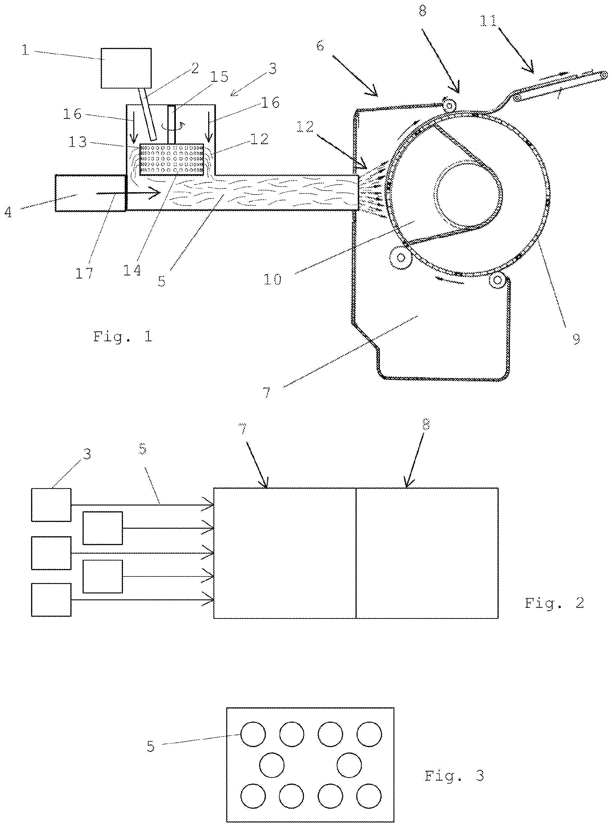
Fig. 1 shows a schematic principle illustration of an apparatus according to the invention,
Fig. 2 shows a schematic principle illustration viewed from above of one possible
placement of fiberizing devices with their channels, and
Fig. 3 shows a schematic principle illustration of one placement of the channels in
the mouth of the collection device, the channels being connected to the fiberizing
devices.
[0009] Reference numeral 1 in Fig. 1 denotes a melting furnace, from which the molten material
is led along a trough 2 into a fiberizing device 3. The fiberizing device 3 is equipped
with a blower 4, which produces a flow 17 of blowing air, which transports the fibres
12 formed by the fiberizing device into the channel 5 and further into the collection
device 6. The collection device 6 has a collection chamber 7 and collector elements
8, which, in this embodiment, comprise a collection drum 9 equipped with a perforated
peripheral surface, inside which is a suction box 10. The blowing air moves through
the holes of the drum 9 into the suction box and further away from the collection
apparatus. This contributes to the collecting of the fibres 12 onto the surface of
the drum 9 to form a primary fibre mat or web, which is then transported, for example,
by a conveyor 11, to the pendulum device (not shown), in which it is formed into a
secondary mat, which is then brought for further processing, for example, hardening.
The collection chamber can as such be according to known art, or it can differ from
known art. The feeding of binder is not shown in the figure. For example, the collection
device can be a foraminous or perforated belt conveyor having suction boxes inside
the belt loop.
[0010] The fiberizing device 3 comprises, rotating around a vertical axis 15, a cup-like
plate 13, on the periphery of which are numerous small holes 14, through which the
molten mass moves under the influence of centrifugal force forming fibres 12, which
are stretched around the plate by vertically led blowing air 16, annularly surrounding
the plate. In connection with the feeding of blowing air and the stretching of the
fibres, binder and other necessary chemicals can be fed. Such a fiberizing plate and
the production of blowing air, surrounding it annularly, in the manufacture of glass
wool is prior known to the skilled person in the art, for example, from
US4759974. The advantage in using such a fiberizing plate is that the majority of the mass
can be fiberized. The disadvantage is that through one fiberizing device can be fed
only approx. 400-500 kg molten mass per hour, which is significantly less than in
solutions implemented with spinner discs, in which the fed amount of molten mass can
be, for example, 5000-7000 kg per hour. In the solution according to the invention,
in connection with the fiberizing device 3, preferably below it, is arranged a relatively
small-diameter, horizontal channel 5 leading to the collection device, the length
of which channel can be several metres, for example, in the range of approx. 1 m -
approx. 10 m. In connection with the channel 5 is arranged a blower 4, which creates
a horizontal air flow in the channel 5 directing the fibres 12, oriented downwards
by the vertical blowing air 16 in the fiberizing device, horizontally along the channel
5 towards the collection device 6. By means of this channel solution, it is possible
to place several fiberizing devices 3 to feed one collection device 6, wherein the
production output can be increased to a desired level. The fiberizing devices are
placed at different height levels with each other and at different horizontal distance
from the collection device 6, wherein only the channels 5 need to be adapted to the
inlet port of the collection device. The channels 5 do not need to all be the same
shape or size, and their location in relation to the collection apparatus can also
be modified.
[0011] Fig. 2 shows as a schematic illustration viewed from above of one placement of the
fiberizing devices 3 in relation to each other, as well as in relation to the collection
chamber 7 and the collector elements 8. Fig. 3 shows schematically an example of one
manner of placing the channels 5 in the mouth of the collection device 6 as viewed
from the direction of the collection drum 9.
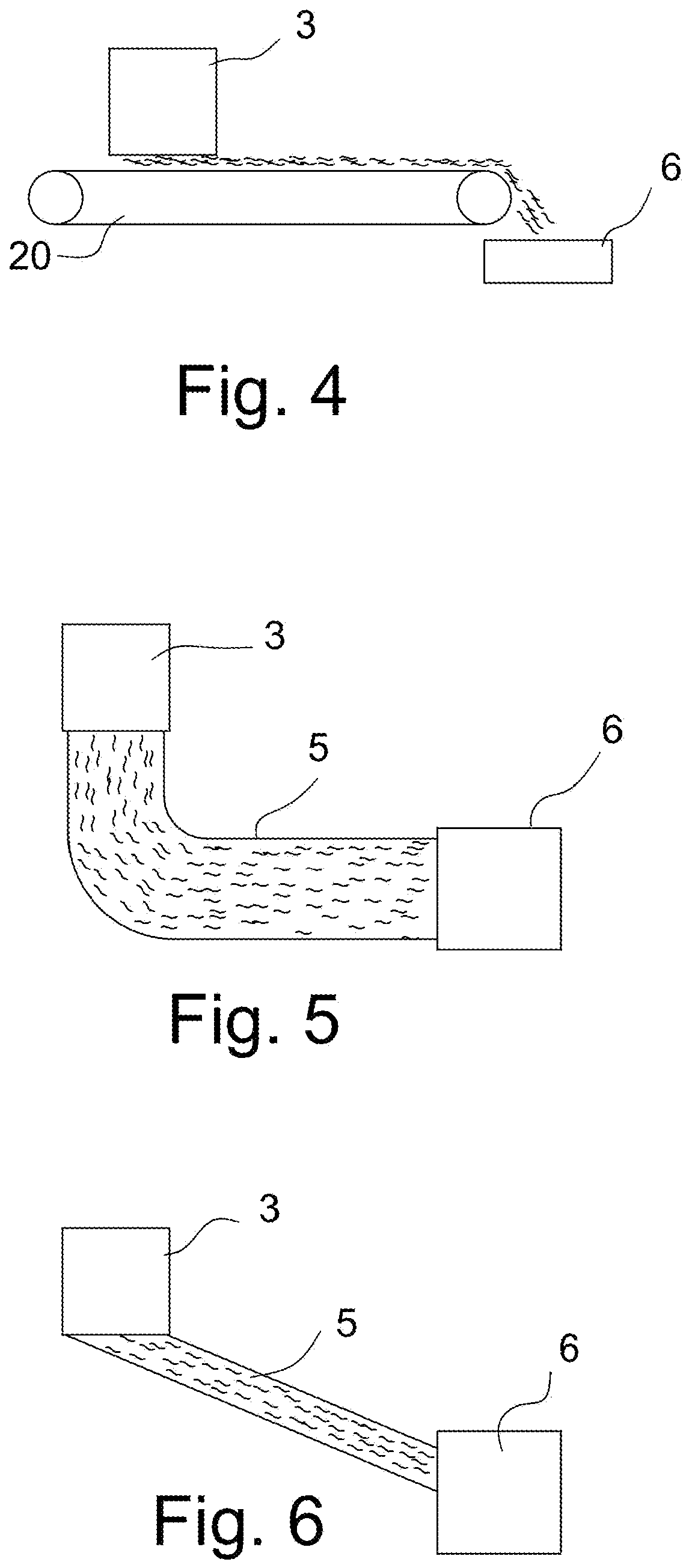
[0012] Fig. 4, which is not part of the invention, shows a schematic illustration of an
apparatus wherein the conveying device comprises a belt 20 on which the fibres are
deposited. The belt can be provided with suction boxes inside the belt loop to assist
depositing of the fibres on the certain portion of upper run of the belt. For releasing
the fibres into a collection device the belt is preferably without any suction means
in the discharging area of the belt loop or there can be blower means for directing
an air flow from inside the belt loop through the belt in the discharging area of
the belt 20 to assist releasing of the fibres.
[0013] Fig. 5, which is not part of the invention, shows a schematic illustration of an
apparatus wherein the conveying device 5 comprises a curved channel 5 through which
the fibres are transported from a fiberizing device 3 to a collection device 6 by
means of the blowing air directed vertically downwards around the fiberizing plate
and/or by means of suction means arranged in the channel in the vicinity of the collection
device.
[0014] Fig. 6, which is not part of the invention, shows a schematic illustration of an
apparatus wherein the conveying device 5 comprises an inclined channel 5 through which
the fibres are transported from a fiberizing device 3 to a collection device by means
of the blowing air directed vertically downwards around the fiberizing plate and/or
by means of suction means arranged in the channel in the vicinity of the collection
device.
[0015] One or more fiberizing plates can be equipped with perforations of different size
in relation to the other fiberizing plates, wherein different fiberizing plates can
be used to produce fibres of different size. Furthermore, different fiberizing plates
can be used to produce different fiberizing parameters, such as, for example, the
rotation speed of the plate, the feeding rate of the molten material and/or the flow
rate of the vertical blowing air, to vary in a desired manner the characteristics
of the intermediate product and/or final product to be manufactured by the apparatus.
[0016] In the solution according to the invention, the fiberizing plates can be similar
to or different from each other, i.e. their dimensions, such as, for example, the
diameters of the fiberizing plates may differ from each other, and the fiberizing
plates may also differ in their design (for example, the height and shape of the edges
of the fiberizing plate).
[0017] By using the method according to the invention, it is possible to create a mineral
wool product having a fibre content in excess of 90%, preferably in excess of 95%,
based on the following standards or specifications:
- 1) Eurima 5 (10.5.1967), Determination of the content of non-fibrous material in mineral
wool
- 2) BS 2972:1975, Method of test for inorganic thermal insulating material, Section
14
- 3) ASTM C 612-83, Annex, Shot content of unorganic fibrous thermal insulation
- 4) JIS A 9504-1984, Heat insulation made of Rockwool.
[0018] The method according to the invention enables the manufacture of a mineral wool product
having the desired tensile strength characteristics, i.e. the transverse tensile strength
of which is greater than the linear tensile strength.
1. An apparatus for manufacturing mineral wool, the apparatus including means (1) for
producing molten mineral material, at least one fiberizing device (3) for forming
fibres, into which fiberizing device the molten mineral material is fed (2) and by
which fibres (12) are formed, the fiberizing device (3) comprising, rotationally arranged
around a vertical axis (15), at least one fiberizing plate (13) having a vertical
peripheral edge, into which are formed numerous small-sized holes (14), through which
the molten material is led by centrifugal force to form fibres (12), wherein to the
fiberizing device (3) are arranged elements to produce a vertical flow of blowing
medium (16) to be led around the fiberizing plate (13), the flow causing the fibres
(12) to turn downwards and, at the same time, to thin, as well as a collection device
(6) arranged downstream the fiberizing device (3), into which the formed fibres (12)
are led and collected into a mat-like material,
characterized in that the apparatus includes at least two fiberizing devices (3), which are placed at different
height levels with each other and at different horizontal distances from the collection
device (6), and that in connection with said at least one fiberizing plate (13) of
each fiberizing device (3) is arranged a conveying device (5), where the fibres (12)
are brought before reaching the collection device (6) and wherein the conveying device
(5) comprises:
a horizontal channel (5) located between the fiberizing plate (13) and collection
device (6), and
air producing means for transporting fibres to the collection device (6).
2. An apparatus according to claim 1, characterized in that the channel (5) is straight or curved.
3. An apparatus according to claim 1, characterized in that the conveying device comprises a belt.
4. An apparatus according to any of claims 1 to 3, characterized in that the collection device (6) has a collection chamber (7) and collector elements (8),
which comprise a collection drum (9) equipped with a perforated peripheral surface,
inside which is a suction box (10), onto which drum the fibres are collected into
a primary mat or web.
5. An apparatus according to claim 1 or 2, characterized in that the length of the channel (5) is in the range of 1-10 m.
6. An apparatus according to any one of claims 1 to 5, characterized in that the diameter of the holes (14) on the periphery of the fiberizing plate (13) is in
the range of approx. 0.3 mm - approx. 2 mm, preferably approx. 0.5 mm - approx. 1
mm.
7. An apparatus according to any one of claims 1 to 6, characterized in that at least one fiberizing plate (13) has holes (14) of different size in relation to
the holes of at least one other fiberizing plate for forming fibres of different thicknesses
by different fiberizing plates.
8. An apparatus according to any one of claims 1 to 7, characterized in that the fiberizing plates are similar to each other.
9. An apparatus according to any one of claims 1 to 7, characterized in that the fiberizing plates are different from each other.
10. A method for manufacturing mineral wool, the method using an apparatus, which includes
means (1) for producing molten mineral material, at least one fiberizing device (3)
for forming fibres, into which fiberizing device the molten mineral material is fed
and by which fibres (12) are formed, the fiberizing device (3) comprising, rotationally
arranged around a vertical axis (15), at least one fiberizing plate (13) having a
vertical peripheral edge, into which are formed numerous small- sized holes (14),
through which the molten material is led by centrifugal force to form fibres (12),
wherein into the fiberizing device (3) are arranged elements to produce an annular
flow of blowing medium (16) directed vertically downwards around the fiberizing plate
(13), the flow causing the fibres (12) to turn downwards and to thin, as well as a
collection device (6) arranged downstream the fiberizing device (3), into which the
formed fibres (12) are led and collected into a mat-like material,
characterized in that, in the method, at least two fiberizing devices (3) are arranged to feed fibres into
a common collection device (6), the fiberizing devices (3) being placed at different
height levels with each other and at different horizontal distances from the collection
device (6), and that in connection with the fiberizing plate (13) of each fiberizing
device (3) is arranged a conveying device (5) where the fibres (12) are brought and
by means of which the fibres are conveyed into the collection device (6) to form a
primary fibre mat or web and wherein the conveying device (5) comprises:
a horizontal channel (5) located between the fiberizing plate (13) and collection
device (6), and
air producing means for transporting fibres to the collection device (6).
11. A method according to claim 10, characterized in that with different fiberizing plates (13) are used different fiberizing parameters and/or
holes of different size (14) to vary in a desired manner the characteristics of the
intermediate product and/or final product to be manufactured by the apparatus.
12. A method according to claim 10, characterized in that blowing medium is used to transport the fibres with the conveying means into the
collection device (6).
13. A method according to claim 10, characterized in that the fiberizing devices (3) are installed in place of an existing fiberizing apparatus
in an existing manufacturing line.
1. Einrichtung zur Herstellung von Mineralwolle, wobei die Einrichtung Mittel (1) zum
Produzieren von geschmolzenem Mineralmaterial, mindestens eine Faserbildungsvorrichtung
(3) zum Bilden von Fasern, wobei das geschmolzene Mineralmaterial in die Faserbildungsvorrichtung
eingespeist (2) wird und von dieser Fasern (12) gebildet werden, wobei die Faserbildungsvorrichtung
(3), um eine vertikale Achse (15) drehbar angeordnet, mindestens eine Faserbildungsplatte
(13) mit einem vertikalen Umfangsrand umfasst, in dem zahlreiche Löcher (14) kleiner
Größe gebildet sind, durch die das geschmolzene Material durch Zentrifugalkraft geleitet
wird, um Fasern (12) zu bilden, wobei an der Faserbildungsvorrichtung (3) Elemente
angeordnet sind, um eine vertikale Strömung eines Blasmediums (16) zu produzieren,
die um die Faserbildungsplatte (13) geleitet werden soll, wobei die Strömung bewirkt,
dass sich die Fasern (12) nach unten wenden und gleichzeitig verdünnen, sowie eine
der Faserbildungsvorrichtung (3) nachgelagert angeordnete Sammelvorrichtung (6) beinhaltet,
in die die gebildeten Fasern (12) geleitet und dort zu einem mattenartigen Material
gesammelt werden,
dadurch gekennzeichnet, dass die Einrichtung mindestens zwei Faserbildungsvorrichtungen (3) beinhaltet, die auf
unterschiedlichen Höhenniveaus zueinander und in unterschiedlichen horizontalen Abständen
von der Sammelvorrichtung (6) platziert sind, und dass in Verbindung mit der mindestens
einen Faserbildungsplatte (13) jeder Faserbildungsvorrichtung (3) eine Fördervorrichtung
(5) angeordnet ist, zu der die Fasern (12) gebracht werden, bevor sie die Sammelvorrichtung
(6) erreichen, und wobei die Fördervorrichtung (5) umfasst:
einen horizontalen Kanal (5), der sich zwischen der Faserbildungsplatte (13) und der
Sammelvorrichtung (6) befindet, und
luftproduzierende Mittel zum Transportieren von Fasern zur Sammelvorrichtung (6).
2. Einrichtung nach Anspruch 1, dadurch gekennzeichnet, dass der Kanal (5) gerade oder gebogen ist.
3. Einrichtung nach Anspruch 1, dadurch gekennzeichnet, dass die Fördervorrichtung ein Band umfasst.
4. Einrichtung nach einem der Ansprüche 1 bis 3, dadurch gekennzeichnet, dass die Sammelvorrichtung (6) eine Sammelkammer (7) und Sammlerelemente (8) aufweist,
die eine mit einer perforierten Umfangsfläche ausgestattete Sammeltrommel (9) umfassen,
in deren Inneren sich ein Saugkasten (10) befindet, wobei die Fasern auf der Trommel
zu einer primären Matte oder Bahn gesammelt werden.
5. Einrichtung nach Anspruch 1 oder 2, dadurch gekennzeichnet, dass die Länge des Kanals (5) im Bereich von 1-10 m liegt.
6. Einrichtung nach einem der Ansprüche 1 bis 5, dadurch gekennzeichnet, dass der Durchmesser der Löcher (14) am Umfang der Faserbildungsplatte (13) im Bereich
von ca. 0,3 mm - ca. 2 mm, bevorzugt ca. 0,5 mm - ca. 1 mm liegt.
7. Einrichtung nach einem der Ansprüche 1 bis 6, dadurch gekennzeichnet, dass zum Bilden von Fasern unterschiedlicher Dicken durch unterschiedliche Faserbildungsplatten
mindestens eine Faserbildungsplatte (13) Löcher (14) unterschiedlicher Größe in Bezug
auf die Löcher mindestens einer anderen Faserbildungsplatte aufweist.
8. Einrichtung nach einem der Ansprüche 1 bis 7, dadurch gekennzeichnet, dass die Faserbildungsplatten einander ähnlich sind.
9. Einrichtung nach einem der Ansprüche 1 bis 7, dadurch gekennzeichnet, dass sich die Faserbildungsplatten voneinander unterscheiden.
10. Verfahren zur Herstellung von Mineralwolle, wobei das Verfahren eine Einrichtung verwendet,
die Mittel (1) zum Produzieren von geschmolzenem Mineralmaterial, mindestens eine
Faserbildungsvorrichtung (3) zum Bilden von Fasern, wobei das geschmolzene Mineralmaterial
in die Faserbildungsvorrichtung eingespeist wird und von dieser Fasern (12) gebildet
werden, wobei die Faserbildungsvorrichtung (3), um eine vertikale Achse (15) drehbar
angeordnet, mindestens eine Faserbildungsplatte (13) mit einem vertikalen Umfangsrand
umfasst, in dem zahlreiche Löcher (14) kleiner Größe gebildet sind, durch die das
geschmolzene Material durch Zentrifugalkraft geleitet wird, um Fasern (12) zu bilden,
wobei in der Faserbildungsvorrichtung (3) Elemente angeordnet sind, um eine ringförmige
Strömung eines Blasmediums (16) zu produzieren, die vertikal nach unten um die Faserbildungsplatte
(13) gerichtet ist, wobei die Strömung bewirkt, dass sich die Fasern (12) nach unten
wenden und verdünnen, sowie eine der Faserbildungsvorrichtung (3) nachgelagert angeordnete
Sammelvorrichtung (6) beinhaltet, in die die gebildeten Fasern (12) geleitet und dort
zu einem mattenartigen Material gesammelt werden,
dadurch gekennzeichnet, dass bei dem Verfahren mindestens zwei Faserbildungsvorrichtungen (3) so angeordnet sind,
dass sie Fasern in eine gemeinsame Sammelvorrichtung (6) einspeisen, wobei die Faserbildungsvorrichtungen
(3) auf unterschiedlichen Höhenniveaus zueinander und in unterschiedlichen horizontalen
Abständen von der Sammelvorrichtung (6) platziert sind, und dass in Verbindung mit
der Faserbildungsplatte (13) jeder Faserbildungsvorrichtung (3) eine Fördervorrichtung
(5) angeordnet ist, zu der die Fasern (12) gebracht werden und mittels der die Fasern
in die Sammelvorrichtung (6) befördert werden, um eine primäre Fasermatte oder -bahn
zu bilden, und wobei die Fördervorrichtung (5) umfasst:
einen horizontalen Kanal (5), der sich zwischen der Faserbildungsplatte (13) und der
Sammelvorrichtung (6) befindet, und
luftproduzierende Mittel zum Transportieren von Fasern zur Sammelvorrichtung (6).
11. Verfahren nach Anspruch 10, dadurch gekennzeichnet, dass bei unterschiedlichen Faserbildungsplatten (13) unterschiedliche Faserbildungsparameter
und/oder Löcher (14) unterschiedlicher Größe verwendet werden, um die Eigenschaften
des Zwischenprodukts und/oder Endprodukts, das von der Einrichtung hergestellt werden
soll, in einer gewünschten Weise zu variieren.
12. Verfahren nach Anspruch 10, dadurch gekennzeichnet, dass ein Blasmedium verwendet wird, um die Fasern mit dem Fördermittel in die Sammelvorrichtung
(6) zu transportieren.
13. Verfahren nach Anspruch 10, dadurch gekennzeichnet, dass die Faserbildungsvorrichtungen (3) anstelle einer bestehenden Faserbildungseinrichtung
in einer bestehenden Fertigungslinie installiert werden.
1. Appareil pour fabriquer de la laine minérale, l'appareil incluant des moyens (1) pour
produire un matériau minéral fondu, au moins un dispositif de défibrage (3) pour former
des fibres, dispositif de défibrage dans lequel le matériau minéral fondu est alimenté
(2) et par lequel des fibres (12) sont formées, le dispositif de défibrage (3) comprenant,
agencée de manière rotative autour d'un axe vertical (15), au moins une plaque de
défibrage (13) présentant un bord périphérique vertical, dans lequel sont formés de
nombreux trous de petite taille (14), à travers lesquels le matériau fondu est conduit
par la force centrifuge pour former des fibres (12), dans lequel dans le dispositif
de défibrage (3) sont agencés des éléments pour produire un flux vertical de milieu
de soufflage (16) à conduire autour de la plaque de défibrage (13), le flux provoquant
le retournement des fibres (12) vers le bas et, en même temps, leur amincissement,
ainsi qu'un dispositif de collecte (6) agencé en aval du dispositif de défibrage (3),
dans lequel les fibres formées (12) sont conduites et collectées en un matériau de
type nappe,
caractérisé en ce que l'appareil inclut au moins deux dispositifs de défibrage (3), qui sont placés à des
niveaux de hauteur mutuellement différents et à différentes distances horizontales
du dispositif de collecte (6), et
en ce qu'en liaison avec ladite au moins une plaque de défibrage (13) de chaque dispositif
de défibrage (3) est agencé un dispositif de transport (5), dans lequel les fibres
(12) sont amenées avant d'atteindre le dispositif de collecte (6), et dans lequel
le dispositif de transport (5) comprend :
un canal horizontal (5) situé entre la plaque de défibrage (13) et le dispositif de
collecte (6), et
des moyens de production d'air pour transporter des fibres vers le dispositif de collecte
(6).
2. Appareil selon la revendication 1, caractérisé en ce que le canal (5) est droit ou incurvé.
3. Appareil selon la revendication 1, caractérisé en ce que le dispositif de transport comprend une courroie.
4. Appareil selon l'une quelconque des revendications 1 à 3, caractérisé en ce que le dispositif de collecte (6) présente une chambre de collecte (7) et des éléments
collecteurs (8), qui comprennent un tambour de collecte (9) équipé d'une surface périphérique
perforée, à l'intérieur duquel se trouve une caisse aspirante (10), tambour sur lequel
les fibres sont collectées en une nappe ou bande primaire.
5. Appareil selon la revendication 1 ou 2, caractérisé en ce que la longueur du canal (5) est dans la plage de 1-10 m.
6. Appareil selon l'une quelconque des revendications 1 à 5, caractérisé en ce que le diamètre des trous (14) sur la périphérie de la plaque de défibrage (13) est dans
la plage d'environ 0,3 mm-environ 2 mm, de préférence d'environ 0,5 mm-environ 1 mm.
7. Appareil selon l'une quelconque des revendications 1 à 6, caractérisé en ce qu'au moins une plaque de défibrage (13) présente des trous (14) d'une taille différente
par rapport aux trous d'au moins une autre plaque de défibrage pour former des fibres
d'épaisseurs différentes par différentes plaques de défibrage.
8. Appareil selon l'une quelconque des revendications 1 à 7, caractérisé en ce que les plaques de défibrage sont semblables les unes aux autres.
9. Appareil selon l'une quelconque des revendications 1 à 7, caractérisé en ce que les plaques de défibrage sont différentes les unes des autres.
10. Procédé de fabrication de laine minérale, le procédé utilisant un appareil, qui inclut
des moyens (1) pour produire un matériau minéral fondu, au moins un dispositif de
défibrage (3) pour former des fibres, dispositif de défibrage dans lequel le matériau
minéral fondu est alimenté et par lequel des fibres (12) sont formées, le dispositif
de défibrage (3) comprenant, agencée de manière rotative autour d'un axe vertical
(15), au moins une plaque de défibrage (13) présentant un bord périphérique vertical,
dans lequel sont formés de nombreux trous de petite taille (14), à travers lesquels
le matériau fondu est conduit par la force centrifuge pour former des fibres (12),
dans lequel dans le dispositif de défibrage (3) sont agencés des éléments pour produire
un flux annulaire de milieu de soufflage (16) dirigé verticalement vers le bas autour
de la plaque de défibrage (13), le flux provoquant le retournement des fibres (12)
vers le bas et leur amincissement, ainsi qu'un dispositif de collecte (6) agencé en
aval du dispositif de défibrage (3), dans lequel les fibres formées (12) sont conduites
et collectées en un matériau de type nappe,
caractérisé en ce que dans le procédé, au moins deux dispositifs de défibrage (3) sont agencés pour alimenter
en fibres un dispositif de collecte commun (6), les dispositifs de défibrage (3) étant
placés à des niveaux de hauteur mutuellement différents et à différentes distances
horizontales du dispositif de collecte (6), et
en ce qu'en liaison avec la plaque de défibrage (13) de chaque dispositif de défibrage (3)
est agencé un dispositif de transport (5) dans lequel les fibres (12) sont amenées
et au moyen duquel les fibres sont transportées dans le dispositif de collecte (6)
pour former une nappe ou bande de fibres primaire, et dans lequel le dispositif de
transport (5) comprend :
un canal horizontal (5) situé entre la plaque de défibrage (13) et le dispositif de
collecte (6), et
des moyens de production d'air pour transporter des fibres vers le dispositif de collecte
(6).
11. Procédé selon la revendication 10, caractérisé en ce qu'avec différentes plaques de défibrage (13) sont utilisés différents paramètres de
défibrage et/ou des trous de différentes tailles (14) pour faire varier de manière
souhaitée les caractéristiques du produit intermédiaire et/ou du produit final à fabriquer
par l'appareil.
12. Procédé selon la revendication 10, caractérisé en ce qu'un milieu de soufflage est utilisé pour transporter les fibres avec les moyens de
transport jusque dans le dispositif de collecte (6).
13. Procédé selon la revendication 10, caractérisé en ce que les dispositifs de défibrage (3) sont installés à la place d'un appareil de défibrage
existant dans une chaîne de fabrication existante.
REFERENCES CITED IN THE DESCRIPTION
This list of references cited by the applicant is for the reader's convenience only.
It does not form part of the European patent document. Even though great care has
been taken in compiling the references, errors or omissions cannot be excluded and
the EPO disclaims all liability in this regard.
Patent documents cited in the description