| (19) |
 |
|
(11) |
EP 3 846 918 B1 |
| (12) |
EUROPEAN PATENT SPECIFICATION |
| (45) |
Mention of the grant of the patent: |
|
02.11.2022 Bulletin 2022/44 |
| (22) |
Date of filing: 05.09.2019 |
|
| (51) |
International Patent Classification (IPC):
|
| (86) |
International application number: |
|
PCT/EP2019/073709 |
| (87) |
International publication number: |
|
WO 2020/049105 (12.03.2020 Gazette 2020/11) |
|
| (54) |
A TOY CONSTRUCTION SET AND A METHOD OF ASSEMBLING SUCH A TOY CONSTRUCTION SET
SPIELZEUGBAUSATZ UND VERFAHREN ZU DESSEN ZUSAMMENBAU
ENSEMBLE DE JEU DE CONSTRUCTION ET PROCÉDÉ D'ASSEMBLAGE D'UN TEL ENSEMBLE DE JEU DE
CONSTRUCTION
|
| (84) |
Designated Contracting States: |
|
AL AT BE BG CH CY CZ DE DK EE ES FI FR GB GR HR HU IE IS IT LI LT LU LV MC MK MT NL
NO PL PT RO RS SE SI SK SM TR |
| (30) |
Priority: |
07.09.2018 DK PA201870579
|
| (43) |
Date of publication of application: |
|
14.07.2021 Bulletin 2021/28 |
| (73) |
Proprietor: LEGO A/S |
|
7190 Billund (DK) |
|
| (72) |
Inventors: |
|
- POFAHL, Harald
7190 Billund (DK)
- NIELSEN, Kari Vinther
7190 Billund (DK)
|
| (74) |
Representative: Guardian
IP Consulting I/S |
|
Diplomvej, Building 381
2800 Kgs. Lyngby
2800 Kgs. Lyngby (DK) |
| (56) |
References cited: :
CA-A1- 2 185 619
US-A- 4 581 793
|
US-A- 2 885 822
US-A1- 2017 106 309
|
|
| |
|
|
|
|
| |
|
| Note: Within nine months from the publication of the mention of the grant of the European
patent, any person may give notice to the European Patent Office of opposition to
the European patent
granted. Notice of opposition shall be filed in a written reasoned statement. It shall
not be deemed to
have been filed until the opposition fee has been paid. (Art. 99(1) European Patent
Convention).
|
The prior art:
[0001] The present invention relates to a toy construction set comprising a number of toy
building blocks forming a construction having multiple coupling sockets arranged in
a spatial or planar pattern, and where the toy building set further comprises a number
of coupling pins and a flexible sheet having at least one hole, and where each of
the coupling pins extends in a longitudinal direction between a first end being shaped
for releasable attachment of the pin to one of the coupling sockets, and a second
end extending away from the coupling socket in the attached position of the pin in
the socket, and where the second end of the pin comprises a head arranged distally
on a neck on the second end of the pin, and where the neck has a cross section allowing
it to pass freely through the hole.
[0002] Toy construction sets are known in various different embodiments, and as an example
US patent application no. 20170106309 discloses such a toy construction system, where the head of the coupling pins are
spherical, and it is possible to pass through the hole in the flexible sheet by elastic
deformation of the flexible sheet.
[0003] US patent no. 2885822 furthermore discloses a toy construction set having coupling pins with a head having
a size preventing that the head can be shifted through the hole in the flexible sheet.
[0004] The toy construction sets provides many different options for attaching sheet elements
to a rigid structure constructed with the building blocks.
The object of the invention:
[0005] On this background it is the purpose of the present invention to provide a construction
set as mentioned in the introduction, and providing the user with further options
for easily building more different constructions with new and intriguing functionality.
[0006] This is obtained by the toy construction set according to claim 1 by having the size
and shape of the hole and the size and shape of the head are adapted such that it
is impossible to pass the head through the hole without tearing or providing a plastic
deformation on the flexible sheet, and by having the neck extending between the head
and a flange surrounding the pin and the size and shape of the flange being such that
passing the flange through the hole requires plastic deformation of the flexible sheet.
[0007] Thereby the flexible sheet is easy to attach to the coupling pin, but at the same
time it is impossible to detach from an assembled construction as long as the coupling
pin is mounted in a coupling socket.
[0008] In a preferred embodiment of the invention the head of the coupling pin is shaped
like a panhead having a flat surface on the side of the head where the neck of the
coupling pin is arranged, and a convex surface on the opposite side. Thereby the risk
of tearing the flexible sheet is reduced if a force is applied to the sheet trying
to pull the sheet over the head.
[0009] In a preferred embodiment of the invention the largest cross section of the head
is in a direction perpendicular to the longitudinal direction larger than the largest
cross section of the hole in the flexible sheet.
[0010] In a further preferred embodiment the hole in the flexible sheet, and the largest
cross section of the head in a direction perpendicular to the longitudinal direction
are both circular.
[0011] Preferably the construction set comprises one or more of said building blocks, each
having multiple coupling sockets arranged equidistantly at least along one straight
line.
[0012] The construction set according to the invention may advantageously comprise two or
more of said building blocks, and at least one connector pin having a first end adapted
for being attached to a coupling socket on one of said building blocks, and an opposite
end adapted for being attached to a coupling socket on the other one of said building
blocks.
[0013] In an especially advantageous embodiment of the invention the flexible sheet is made
from an elastically bendable material. Thereby the bending elasticity of the flexible
sheet, along with the secure attachment of the sheet to the coupling pin provides
various new functionalities without the risk that the flexible sheet disengages from
the coupling pin.
[0014] In this relation the couplings sockets are preferably formed by a substantially cylindrical
through hole extending through the building block.
[0015] The invention also provides a computer-readable model comprising computer-readable
instructions configured to cause, when processed by an apparatus for performing an
additive manufacturing process, said apparatus to manufacture the toy building elements
as defined above.
[0016] Furthermore the invention provides a method of assembling at toy construction set
according to one or more of the preceding claims, wherein the coupling pin is first
attached to the flexible sheet by passing the first end of the coupling pin through
the hole in the flexible sheet, and thereafter the first end of the coupling pin is
attached to the coupling socket of one of the toy building blocks.
The drawing:
[0017] In the following one or more embodiments of the invention will be described in more
detail and with reference to the drawing, where:
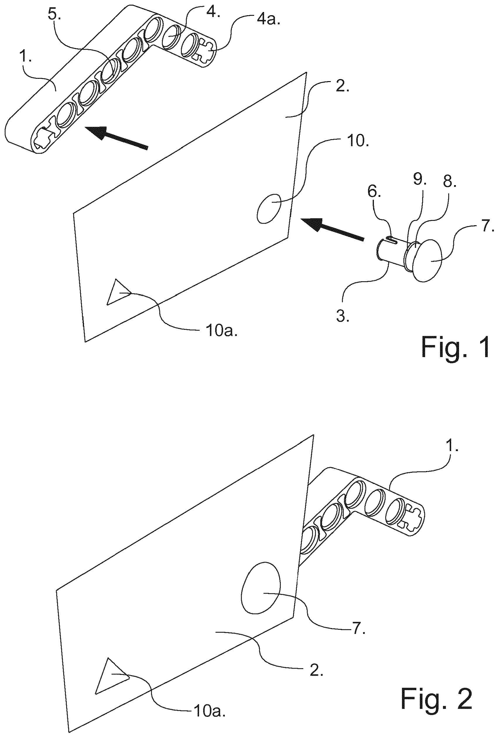
Fig. 1: Is a perspective view showing one embodiment of a toy construction set according
to the present invention before assembly.
Fig. 2: Is a perspective view of the toy construction set shown in fig. 1 after assembly.
Fig. 3: Is a detailed side view of one as shown in fig. 1 and 2.
Fig. 4: Is a side view of a connector pin to be used with the toy construction set
shown in fig. 1 and 2.
Fig. 5: Is a side view of an alternative embodiment of the coupling pin according
to the invention.
Description of exemplary embodiments:
[0018] Fig. 1 shows a very simple embodiment of a toy construction set according to the
invention, having only a single building block 1, a flexible sheet 2, and a coupling
pin 3 adapted for interconnecting the building block 1 with the flexible sheet 2 to
form a combined construction.
[0019] The building block 1 has two legs forming a V, and each of the legs has a row of
coupling sockets 4 arranged equidistantly along a straight line, and being formed
as cylindrical through holes with a recess 5 arranged at each end of the through hole.
[0020] In the end of each of the legs on the building block 1 a second type of coupling
socket 4a are arranged being formed as a splined through hole.
[0021] Building blocks of this type, are well known in the prior art having many different
shapes and sizes allowing the user to construct various different structures e.g.
by interconnecting two or more such building blocks using a connector pin 17 as shown
in figure 4 formed as a cylindrical pin having oppositely arranged ends that extend
away from a mid-flange 18, and due to the cutouts 20, and the distally arranged end
flanges 19 each may be snap fitted into one coupling socket 4 on two different building
blocks, so that the mid-flange 18 and the end flanges 19 fits into the recesses 5
on each end of the coupling sockets 4.
[0022] In this way it is possible to construct both simple and complex and rigid or articulating
structures such as toy sailing ships, toy tents, toy flag poles and the like, and
by providing the opportunity of mounting a sheet 2 on such structures, then it is
possible to construct such toy structures that more realistically resembles real such
sailing ships, tents, flag poles and the like, where the sheet 2 respectively resembles
the sails, the tent canvas or the flag.
[0023] It is therefore apparent to the skilled person that the present invention is applicable
to any such constructions, and toy construction sets.
[0024] According to this embodiment of the invention the sheet 2 has a hole 10 and is possible
to attach to the building block/building element 1 by using a substantially cylindrical
coupling pin 3 as shown in figure 1 and 3 by inserting the first end 11 of the substantially
cylindrical coupling pin 3 through the hole 10 in the sheet 2, and into a snap engagement
with one of the coupling sockets 4 formed by cylindrical through holes in the building
block 1. According to this embodiment of the invention the head 7 of the coupling
pin 3 has a cross section in a plane being perpendicular to the longitudinal symmetry
axis 12 of the coupling pin 3 that is much larger than the width of the diameter of
the circular hole 10 in the sheet, so that it securely attached to the building block
1 due to the fact that it is impossible to pass the head 7 through the hole 10 without
tearing or providing a plastic deformation of the sheet 2.
[0025] It will be apparent to the skilled person that it is possible, according to the invention,
to design various different shapes and sizes of the hole 10 in the sheet 2 and corresponding
shapes and sizes of the head 7 of the coupling pin 3, and to select a sheet material
og the sheet 2 having an elasticity so that it is not possible to pass the head 7
thorough the hole 10 without tearing the material of the sheet 2 or at least forming
a permanent/plastic deformation of the sheet material around the hole 10.
[0026] As an example the sheet 2 shown in figure 1 and 2 also has a second hole 10a, being
triangular with a side length so that it allows the intermediate flange 9 mentioned
below to pass the hole 10a.
[0027] In the embodiment shown in figure 1 and 3 the head 7 is formed as a panhead having
a flat surface on the side facing the sheet 2 and a convex surface 16 facing away
from the sheet 2 when it is attached to the coupling pin as shown on figure 3. In
this embodiment the coupling pin 3 also has a neck 8 extending between the panhead
10 and an intermediate flange 9, and the diameter of the flange is in this embodiment
smaller than the diameter of the hole 10, whereas the diameter of the flange 9 is
a little larger than the diameter of the hole 10, so that is possible to pass the
flange 9 through the hole 10 by elastic deformation of the sheet. Thereby it is possible
to attach the coupling pin 3 to the sheet 2 without the risk of losing the coupling
pin 3 when handling the sheet 2 before it is attached to the building block 2 as shown
on figure 2.
[0028] In some embodiments the holes have a triangular shape. This allows the flange to
pass through the hole by elastic deformation of the hole while reducing the risk of
damaging the sheet.
[0029] In the same way as the connector pin 17 is possible to snap into one of the coupling
sockets 4 on the building element, then the coupling pin 3 shown in figure 3 is possible
to snap into any one of the cylindrically shaped coupling sockets 4 on the building
block 1, where the intermediate flange 9 fits into the recess 5 on one side of the
coupling socket 4. In this way the same coupling socket 4 may be used for either interconnecting
building blocks 1 or for attaching coupling pins 3.
[0030] In this relation this embodiment of the invention also comprises a second type of
coupling sockets 4a that are shaped as splined through holes where a second type of
coupling pin 24 as shown in figure 5 having a splined axle end are to be inserted
into and held in place by friction.
1. A toy construction set comprising a number of toy building blocks (1) forming a construction
having a number of coupling sockets (4) arranged in a spatial or planar pattern, and
where the toy building set further comprises a number of coupling pins (3) and a flexible
sheet (2) having at least one hole (10, 10a), and where each of the coupling pins
(3) extends in a longitudinal direction between a first end (11) being shaped for
releasable attachment of the pin to one of the coupling sockets (4), and a second
end extending away from the coupling socket (4) in the attached position of the pin
(3) in the socket (4), and where the second end of the pin (3) comprises a head (7)
arranged distally on a neck (8) on the second end of the pin (3), and where the neck
(8) has a cross section allowing it to pass freely through the hole (10,10a), and
where the size and shape of the hole (10, 10a) and the size and shape of the head
(7) are adapted such that it is impossible to pass the head (7) through the hole (10,
10a) without tearing or providing a plastic deformation on the flexible sheet (2),
wherein the neck (8) extends between the head (7) and a flange (9) surrounding the
pin (3), and the size and shape of the flange (9) is such that passing the flange
(9) through the hole (10, 10a) requires plastic deformation of the flexible sheet
(2).
2. A toy construction set according to claim 1, wherein the head (7) is shaped like a
panhead, or having a flat surface at the side of the head (15) facing the neck (8).
3. A toy construction set according to claim 1 or 2, wherein the hole (10a) is triangular.
4. A toy construction set according to claim 3, wherein the cross section of the neck
(8) is circular having a diameter being smaller than the corresponding diameter of
the circle circumscribing the triangular hole (10a).
5. A toy construction set according to claim 3 or 4, wherein the cross section of the
flange (9) is circular having a diameter being larger than the corresponding diameter
of the circle inscribing the triangular hole (10a).
6. A toy construction set according to one or more of the preceding claims, wherein the
largest cross section of the head (7) is in a direction perpendicular to the longitudinal
direction is larger than the largest cross section of the hole (10) in the flexible
sheet (2).
7. A toy construction set according to claim 6, wherein the hole (10, 10a) in the flexible
sheet (2), and the largest cross section of the head (7) in a direction perpendicular
to the longitudinal direction are both circular.
8. A toy construction set according to one or more of the preceding claims, wherein the
construction set comprises one or more of said building blocks (1), each having multiple
coupling sockets (4) arranged equidistantly at least along one straight line.
9. A toy construction set according to one or more of the preceding claims, wherein the
construction set comprises two or more of said building blocks (1), and at least one
connector pin (17) having a first end adapted for being attached to a coupling socket
(4) on one of said building blocks, and an opposite end adapted for being attached
to a coupling socket (4) on the other one of said building blocks (1).
10. A toy construction set according to one or more of the preceding claims, wherein the
flexible sheet (2) is made from an elastically bendable material.
11. A toy construction set according to one or more of the preceding claims, wherein each
of the couplings sockets (4) are formed by a substantially cylindrical through hole
extending through the building block (1).
12. A computer-readable model comprising computer-readable instructions configured to
cause, when processed by an apparatus for performing an additive manufacturing process,
said apparatus to manufacture the toy building elements as defined in one or more
of claims 1 through 10.
13. A method of assembling a toy construction set according to claims 1 to 11, wherein
the coupling pin (3) is first attached to the flexible sheet (2) by passing the first
end (11) of the coupling pin through the hole (10, 10a) in the flexible sheet (2),
and thereafter the first end (11) of the coupling pin (3) is attached to the coupling
socket (4) of one of the toy building blocks (1).
1. Spielzeug-Konstruktionsset, umfassend eine Reihe von Spielzeug-Bausteinen (1), die
eine Konstruktion mit einer Reihe von Steckhülsen (4) bilden, die in einem räumlichen
oder ebenen Muster angeordnet sind und wobei das Spielzeug-Bausteinset weiter eine
Reihe von Steckzapfen (3) und eine flexible Steckplatte (2) umfasst, das mindestens
ein Loch (10, 10a) aufweist, und wobei sich jeder der Steckzapfen (3) in einer Längsrichtung
zwischen einem ersten Ende (11), das zum lösbaren Befestigen des Zapfen an einer der
Steckhülsen (4) geformt ist, und einem zweiten Ende, das sich von dem Steckzapfen
(4) weg in der befestigten Position des Zapfens (3) in der Hülse (4) erstreckt, und
wobei das zweite Ende des Zapfens (3) einen Kopf (7) umfasst, der distal an einem
Hals (8) an dem zweiten Ende des Zapfens (3) angeordnet ist, und wobei der Hals (8)
einen Querschnitt aufweist, der es ermöglicht, sich frei durch das Loch (10, 10a)
hindurchzuführen, und wobei die Größe und Form des Lochs (10, 10a) und die Größe und
Form des Kopfes (7) derart angepasst sind, sodass es unmöglich ist, den Kopf (7) durch
das Loch (10, 10a) ohne Reißen oder Bereitstellen einer plastischen Verformung an
der flexiblen Steckplatte (2) hindurchzuführen, wobei sich der Hals (8) zwischen dem
Kopf (7) und einem Flansch (9), der den Zapfen (3) umgibt, erstreckt und die Größe
und Form des Flanges (9) derart bemessen sind, soddass ein Hindurchführen des Flansches
(9) durch das Loch (10, 10a) eine plastische Verformung der flexiblen Steckplatte
(2) erfordert.
2. Spielzeug-Konstruktionsset nach Anspruch 1, wobei der Kopf (7) wie ein Flachkopf geformt
ist oder eine flache Fläche an der Seite des Kopfes (15) gegenüber dem Hals (8) aufweist.
3. Spielzeug-Konstruktionsset nach Anspruch 1 oder 2, wobei das Loch (10a) dreieckig
ist.
4. Spielzeug-Konstruktionsset nach Anspruch 3, wobei der Querschnitt des Halses (8) kreisförmig
ist, mit einem Durchmesser, der kleiner als der entsprechende Durchmesser des Kreises
ist, der das dreieckige Loch (10a) umschreibt.
5. Spielzeug-Konstruktionsset nach Anspruch 3 oder 4, wobei der Querschnitt des Flansches
(9) kreisförmig ist, mit einem Durchmesser, der größer als der entsprechende Durchmesser
des Kreises ist, der das dreieckige Loch (10a) umschreibt.
6. Spielzeug-Konstruktionsset nach einem der vorstehenden Ansprüche, wobei der größte
Querschnitt des Kopfes (7), der in einer senkrechten Richtung zur Längsrichtung verläuft,
größer als der größte Querschnitt des Lochs (10) in der flexiblen Steckplatte (2)
ist.
7. Spielzeug-Konstruktionsset nach Anspruch 6, wobei das Loch (10, 10a) in der flexiblen
Steckplatte (2) und der größte Querschnitt des Kopfes (7) in einer senkrechten Richtung
zur Längsrichtung beide kreisförmig sind.
8. Spielzeug-Konstruktionsset nach einem der vorstehenden Ansprüche, wobei das Konstruktionsset
einen oder mehrere der Bausteine (1) umfasst, wobei jeder davon mehrfache Steckhülsen
(4) aufweist, die mindestens entlang einer geraden Linie in gleichen Abständen angeordnet
sind.
9. Spielzeug-Konstruktionsset nach einem der vorstehenden Ansprüche, wobei das Konstruktionsset
zwei oder mehr der Bausteine (1) und mindestens einen Steckerstift (17) umfasst, der
ein erstes Ende aufweist, das angepasst ist, um an einer Steckhülse (4) an einem der
Bausteine befestigt zu werden, und ein zweites Ende, das angepasst ist, um an einer
Steckhülse (4) an dem anderen der Bausteine (1) befestigt zu werden.
10. Spielzeug-Konstruktionsset nach einem der vorstehenden Ansprüche, wobei die flexible
Steckplatte (2) aus einem elastisch biegbaren Material hergestellt ist.
11. Spielzeug-Konstruktionsset nach einem der vorstehenden Ansprüche, wobei jede der Steckhülsen
(4) durch eine im Wesentlichen zylindrische Durchgangsbohrung, die sich durch den
Baustein (1) hindurch erstreckt, geformt ist.
12. Computer-lesbares Modell, umfassend computer-lesbare Anweisungen, das konfiguriert
ist, um zu veranlassen, dass wenn durch eine Einrichtung zum Durchführen eines zusätzlichen
Herstellungsprozesses verarbeitet, die Einrichtung Spielzeug-Bauelemente, wie in einem
der Ansprüche 1 bis 10 definiert, herstellt.
13. Verfahren zum Zusammensetzen eines Spielzeug-Konstruktionssets nach Anspruch 1 bis
11,
wobei der Steckzapfen (3) zuerst an der flexiblen Steckplatte (2) befestigt wird,
indem das erste Ende (11) des Steckzapfens durch das Loch (10, 10a) in der flexiblen
Steckplatte (2) hindurchgeführt wird und danach das erste Ende (11) des Steckzapfens
(3) an der Steckhülse (4) eines der Spielzeug-Bausteine (1) befestigt wird.
1. Jeu de construction comprenant un certain nombre de blocs de jeu de construction (1)
créant une construction qui présente un certain nombre de douilles d'accouplement
(4) agencées en une configuration spatiale ou plane, et où le jeu de construction
comprend en outre un certain nombre de tiges d'accouplement (3) et une feuille flexible
(2) présentant au moins un trou (10, 10a), et où chacune des tiges d'accouplement
(3) s'étend dans une direction longitudinale entre une première extrémité (11) qui
est formée pour une attache libérable de la tige à une des douilles d'accouplement
(4), et une seconde extrémité s'étendant à distance de la douille d'accouplement (4)
dans la position attachée de la tige (3) dans la douille (4), et où la seconde extrémité
de la tige (3) comprend une tête (7) agencée de manière distale sur un collet (8)
sur la seconde extrémité de la tige (3), et où le collet (8) présente une coupe transversale
lui permettant de passer aisément à travers le trou (10, 10a), et où la taille et
la forme du trou (10, 10a) et la taille et la forme de la tête (7) sont adaptées de
telle sorte qu'il soit impossible de passer la tête (7) à travers le trou (10, 10a)
sans déchirer ni produire une déformation plastique sur la feuille flexible (2), dans
lequel le collet (8) s'étend entre la tête (7) et une bride (9) entourant la tige
(3), et la taille et la forme de la bride (9) sont telles qu'un passage de la bride
(9) à travers le trou (10, 10a) exige une déformation plastique de la feuille flexible
(2).
2. Jeu de construction selon la revendication 1, dans lequel la tête (7) est formée comme
une tête cylindrique large, ou présentant une surface plane au niveau du côté de la
tête (15) faisant face au collet (8).
3. Jeu de construction selon la revendication 1 ou 2, dans lequel le trou (10a) est triangulaire.
4. Jeu de construction selon la revendication 3, dans lequel la coupe transversale du
collet (8) est circulaire présentant un diamètre qui est plus petit que le diamètre
correspondant du cercle circonscrivant le trou (10a) triangulaire.
5. Jeu de construction selon la revendication 3 ou 4, dans lequel la coupe transversale
de la bride (9) est circulaire présentant un diamètre qui est plus grand que le diamètre
correspondant du cercle inscrivant le trou (10a) triangulaire.
6. Jeu de construction selon une ou plusieurs des revendications précédentes, dans lequel
la coupe transversale la plus grande de la tête (7) est dans une direction perpendiculaire
à la direction longitudinale est plus grande que la coupe transversale la plus grande
du trou (10) dans la feuille flexible (2).
7. Jeu de construction selon la revendication 6, dans lequel le trou (10, 10a) dans la
feuille flexible (2), et la coupe transversale la plus grande de la tête (7) dans
une direction perpendiculaire à la direction longitudinale sont tous les deux circulaires.
8. Jeu de construction selon une ou plusieurs des revendications précédentes, dans lequel
le jeu de construction comprend un ou plusieurs desdits blocs de construction (1),
chacun présentant de multiples douilles d'accouplement (4) agencées à égale distance
au moins le long d'une ligne droite.
9. Jeu de construction selon une ou plusieurs des revendications précédentes, dans lequel
le jeu de construction comprend deux ou plus desdits blocs de construction (1), et
au moins une tige de liaison (17) présentant une première extrémité adaptée pour être
attachée à une douille d'accouplement (4) sur un desdits blocs de construction, et
une extrémité opposée adaptée pour être attachée à une douille d'accouplement (4)
sur l'autre desdits blocs de construction (1).
10. Jeu de construction selon une ou plusieurs des revendications précédentes, dans lequel
la feuille flexible (2) est faite d'un matériau pliable élastiquement.
11. Jeu de construction selon une ou plusieurs des revendications précédentes, dans lequel
chacune des douilles d'accouplement (4) est créée par un trou traversant sensiblement
cylindrique qui s'étend à travers le bloc de construction (1).
12. Modèle lisible par ordinateur comprenant des instructions lisibles par ordinateur
configurées pour amener, lorsqu'elles sont traitées par un appareil permettant de
réaliser un processus de fabrication additive, ledit appareil à fabriquer les éléments
de jeu de construction tels que définis dans une ou plusieurs des revendications 1
à 10.
13. Procédé d'assemblage d'un jeu de construction selon les revendications 1 à 11,
dans lequel la tige d'accouplement (3) est tout d'abord attachée à la feuille flexible
(2) en passant la première extrémité (11) de la tige d'accouplement à travers le trou
(10, 10a) dans la feuille flexible (2), et par la suite la première extrémité (11)
de la tige d'accouplement (3) est attachée à la douille d'accouplement (4) d'un des
blocs de jeu de construction (1).

REFERENCES CITED IN THE DESCRIPTION
This list of references cited by the applicant is for the reader's convenience only.
It does not form part of the European patent document. Even though great care has
been taken in compiling the references, errors or omissions cannot be excluded and
the EPO disclaims all liability in this regard.
Patent documents cited in the description