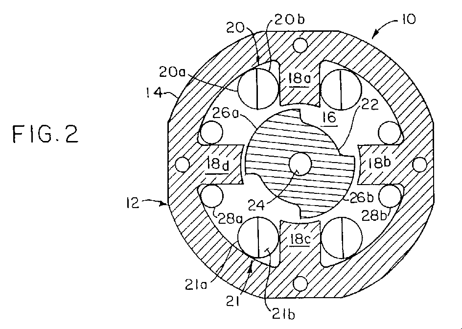
(57) A dynamo-electric machine such as a switched reluctance motor (10). A stator (14)
has a central bore (16) and a plurality of inwardly salient poles (18A-18D) extending
into the bore. A rotor (22) is mounted on a shaft (24) for rotation relative to the
stator. The rotor has a plurality of outwardly salient poles (26A, 26B) extending
into the bore. Stator windings (20, 21) are bifilar windings which produce an electro-magnetic
field when a phase is energized. The bifilar windings return energy to the voltage
source when the phase is de-energized. An auxiliary winding (28) is also installed
on the stator. The auxiliary winding is energized, when the machine is off, to produce
a magnetic field which causes rotation of the rotor to a preferred aligned position
relative to the stator poles. This facilitates subsequent starting of the machine.
An electrical circuit (30) energizes the auxiliary winding, when the machine is off;
and then energizes the stator windings when the machine is started. The circuit de-energizes
the auxiliary winding when the stator windings are energized. The auxiliary windings
are also effective when used with motors having a stepped air gap (G) between the
stator poles and rotor poles, or when the stator has a shifted pole configuration.
|

|
