| (19) |
 |
|
(11) |
EP 1 495 208 B1 |
| (12) |
EUROPEAN PATENT SPECIFICATION |
| (45) |
Mention of the grant of the patent: |
|
17.02.2010 Bulletin 2010/07 |
| (22) |
Date of filing: 03.04.2003 |
|
| (51) |
International Patent Classification (IPC):
|
| (86) |
International application number: |
|
PCT/DK2003/000218 |
| (87) |
International publication number: |
|
WO 2003/087519 (23.10.2003 Gazette 2003/43) |
|
| (54) |
A MULTI LAYER PANE UNIT WITH A BUILT-IN ADJUSTABLE LIGHT SCREENING DEVICE AND AN INSULATION
WINDOW HAVING SUCH A PANE UNIT
MEHRLAGIGE SCHEIBENEINHEIT MIT EINGEBAUTER VERSTELLBARER LICHTBLENDVORRICHTUNG UND
ISOLIERFENSTER MIT SOLCH EINER SCHEIBENEINHEIT
VITRE MULTICOUCHE INTEGRANT UN ECRAN ANTI-LUMIERE REGLABLE ET FENETRE ISOLANTE EQUIPEE
D'UNE TELLE VITRE
|
| (84) |
Designated Contracting States: |
|
AT BE BG CH CY CZ DE DK EE ES FI FR GB GR HU IE IT LI LU MC NL PT RO SE SI SK TR |
|
Designated Extension States: |
|
AL LT LV MK |
| (30) |
Priority: |
15.04.2002 DK 200200554
|
| (43) |
Date of publication of application: |
|
12.01.2005 Bulletin 2005/02 |
| (73) |
Proprietor: VKR Holding A/S |
|
2970 Hørsholm (DK) |
|
| (72) |
Inventors: |
|
- LARSEN, Thomas, Tvedergaard
DK-6760 Ribe (DK)
- ULRIKSEN, Ulrik
DK-6900 Skjern (DK)
|
| (74) |
Representative: Nielsen, Kim Garsdal et al |
|
Internationalt Patent-Bureau A/S
Rigensgade 11
1316 Copenhagen K
1316 Copenhagen K (DK) |
| (56) |
References cited: :
EP-A1- 0 611 873
US-A- 3 722 572
|
US-A- 3 201 832
US-B1- 6 272 811
|
|
| |
|
|
- PATENT ABSTRACTS OF JAPAN vol. 1995, no. 10 30 November 1995 & JP 07 194 092 A (MINORU
KOBAYASHI) 28 July 1995
|
|
| |
|
| Note: Within nine months from the publication of the mention of the grant of the European
patent, any person may give notice to the European Patent Office of opposition to
the European patent
granted. Notice of opposition shall be filed in a written reasoned statement. It shall
not be deemed to
have been filed until the opposition fee has been paid. (Art. 99(1) European Patent
Convention).
|
[0001] The invention relates to a multi-layer pane unit with a built-in, adjustable light
screening device arranged between two plane-parallel glass layers, which at their
side edges are kept at a mutual distance from each other by spacer members for airtight
edge sealing of the space between the glass layers, a rotatable driving device for
the screening device being arranged in said space along one of the side edges thereof
for coupling with an external drive unit by means of a rotatable magnet coupling comprising
an internal magnet member in driving connection with the rotatable driving device
and an external magnet member positioned outside said space in driving connection
with the external drive unit, said magnet members being co-axially journaled with
poles facing each other on respective sides of an interface section of the airtight
sealed space said interface section being formed by a comparatively thin wall part
in a member forming part of the edge sealing in connection with a bearing for the
external magnet member.
[0002] Insulation windows with multi-layer units of this type are known from
US patents Nos. 3,201,832 and
3,722,572 as well as from
EP 0 749 514 B1 and published Japanese patent application No.
7-194092. It is known in substance from these publications to use power transmission from
the external drive unit to the rotable driving device of the screening device by means
of a magnet coupling, for which the interface section between the internal and external
magnet members is provided by a part of the internal glass layer of the insulation
pane unit, resulting in a comparatively pronounced, visible interference with the
light area of the window and furthermore sets a comparatively low limit to the thickness
of the internal glass layer. In the design known from said Japanese patent application
a magnet coupling is used, which is positioned at one end of an elongate housing for
the driving device of the light screening device and coaxially with said driving device.
In this design, the magnet members are designed as coaxial, tubular magnets, both
positioned inwardly with respect to the spacer members providing the edge sealing,
such that an input shaft for the external magnet member penetrates the spacer member
along one side edge of the pane unit. The use of tubular magnets and a likewise tubular
partition wall positioned coaxially between said magnets as well as penetration of
the spacer member result in a complicated design, which makes this design less suitable
for industrial production.
[0003] EP 0 519 972 discloses another design of an insulation window with a built-in light screening
device having a direct power transmission from an external drive unit to the rotatable
driving device of the screening device, a corner member at one end of the housing
of the rotatable driving device forming an airtight passage for a drive shaft for
the rotatable driving device. This design requires a comparatively complicated sealing
arrangement.
[0004] On this background the object of the invention is to provide a design of a multi-layer
pane unit of the type stated, in which said disadvantages are eliminated by means
of a stable magnet coupling of a simple structure and which does not significantly
interfere with the light area.
[0005] To meet this object a multi-layer pane unit of the type stated is according to the
invention characterized in, that that the external drive unit comprises a transmission
device (19) in connection with the member forming part of the edge sealing between
an output shaft coupled to the external magnet member and an input shaft substantially
parallel to said output shaft for connection to a driving device.
[0006] In a preferred embodiment the external drive unit comprises a transmission device
in connection with the member forming part of the edge sealing between an output shaft
coupled to the external magnet member and an input shaft substantially parallel to
said output shaft for connection to a driving device.
[0007] As the parallel output and input shafts of the transmission extend in parallel to
the glass layers, the pane unit may be mounted in a sash or frame structure of an
insulation window without any substantial interference with said sash or frame structure.
[0008] In an advantageous embodiment of the pane unit the glass layers with associated edge
sealing are fitted in a frame of profile members, which towards the light area of
the pane unit form grooves for accommodation of the side edges and glazing beads of
the pane unit and part of said transmission device may be accommodated in a transmission
housing mounted in an upper part of said groove in continuation of the glazing bead
arranged in the groove, the input-shaft being passed through a wall of said transmission
housing facing the light area of the window.
[0009] Further, the invention relates to an insulation window comprising a multi-layer pane
unit as stated above and a surrounding, substantially rectangular sash composed of
mutually perpendicular sash members and with said one side edge of the pane unit in
connection with an upper sash member.
[0010] Further advantageous embodiments of the multi-layer unit according to the invention
are described in the dependent claims 2 - 12.
[0011] The invention will now be explained in detail in the following with reference to
the schematic drawing, in which:
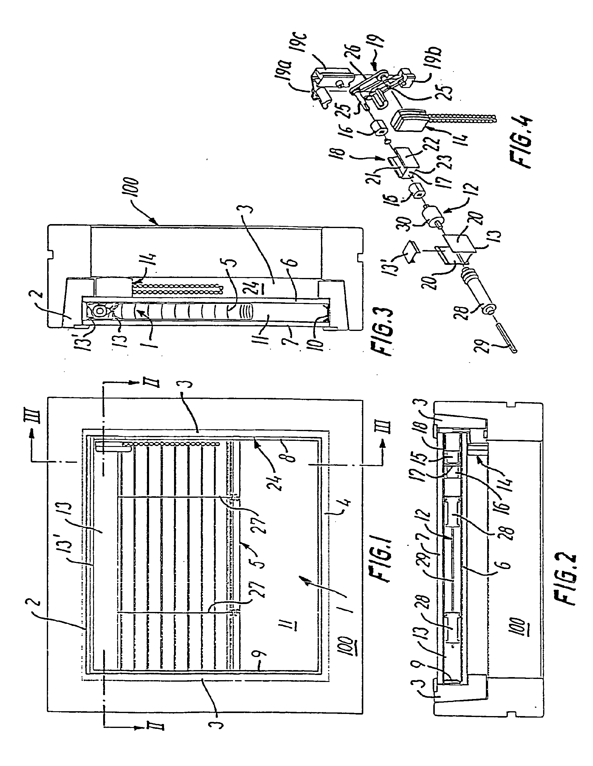
Fig. 1 shows an embodiment of the insulation window according to the invention, seen
from the internal side;
Figs 2 and 3 are sectional views of the window in Fig. 1 along the section lines II-II
and III-III in Fig. 1;
Fig. 4 is an exploded view of a rotatable driving device for the light screening device
for the window in Figs 1 - 3; and
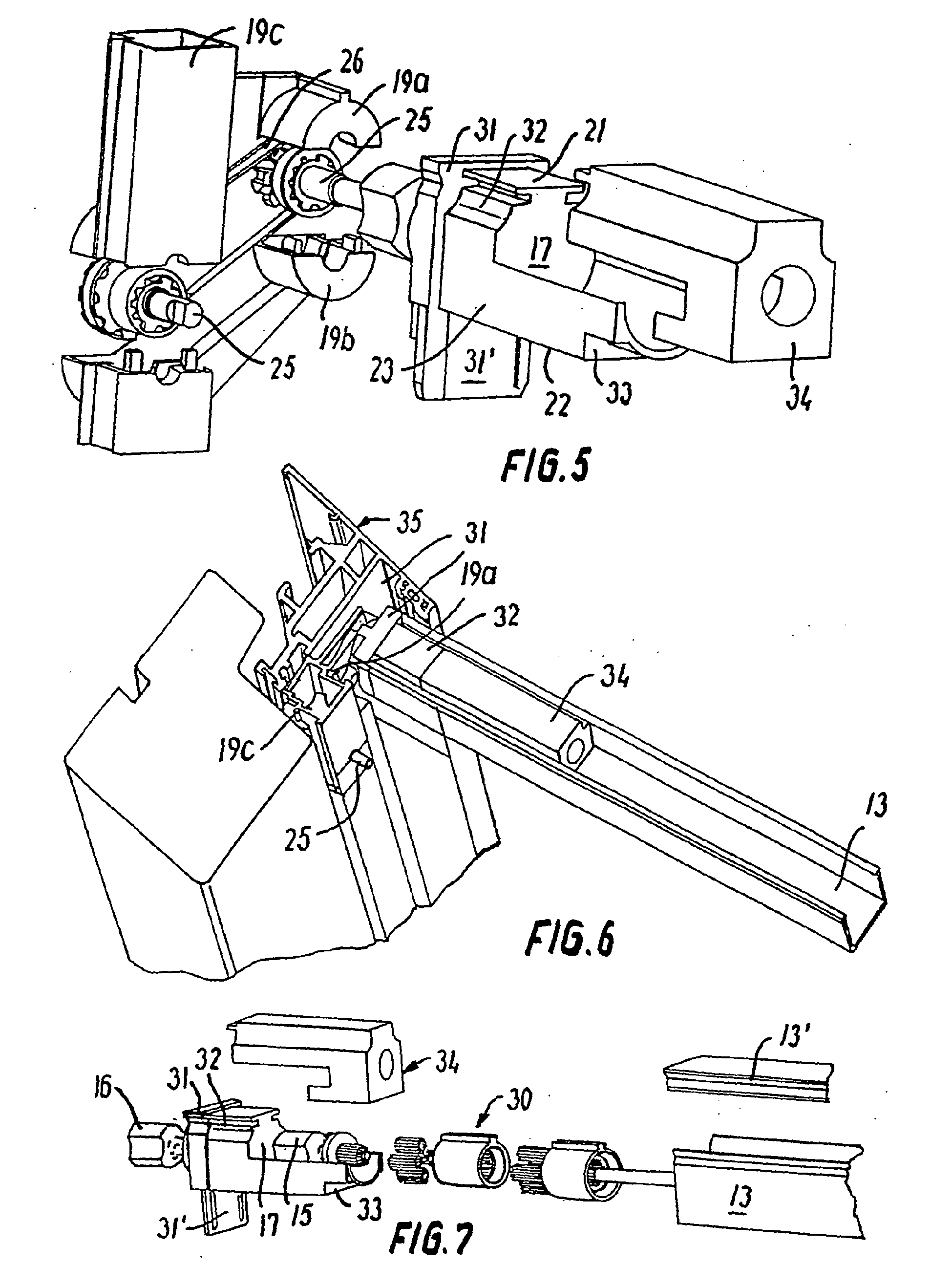
Figs 5, 6 and 7 show details in the magnet coupling at a larger scale in a second,
mirror reversed embodiment.
[0012] The insulation window shown in Figs 1 - 3 has a rectangular sash composed of sash
members 2, 3, 4 perpendicular to one another. The sash is mounted in an intermediate
or main frame 100.
[0013] In the sash a multi-layer pane unit 1 is mounted with an adjustable light screening
device 5 arranged between two plane-parallel glass layers 6, 7, which are kept at
a mutual distance by spacer members 8, 9, 10 preferably in connection with a sealing
compound for provision of an airtight edge sealing of the space 11 between the glass
layers 6 and 7.
[0014] In the embodiment shown, a rotatable driving device 12 for the screening device 1
is positioned in a housing 13 having a cover 13' functioning as a spacer member and
forming part of the edge sealing between the glass layers 6, 7. The housing 13 has
the form of a U-shaped rail profile with side walls 20 engaging the cover 13' along
one sash member 2. The driving device 12 is connected to an external drive unit, which
in the embodiment shown has the form of a cord drive 14, by means of a rotatable magnet
coupling comprising an internal magnet member 15, which is in driving connection with
the rotatable driving device 12, and an external magnet member 16 positioned outside
the edge sealing in driving connection with the external drive unit 14. The magnet
members 15, 16 are arranged such that their poles face one another, but the magnets
15, 16 are positioned on respective sides of a thin transverse wall 17 in a corner
member 18 provided at the end of the housing 13 which faces a sash member 3 perpendicular
to the sash member 2 along which the housing 13 extends. The thin transverse wall
17 constitutes a wall part of the airtight sealed space 11 between the glass layers
6, 7.
[0015] However, the housing 13 is not absolutely necessary, given the screening device with
associated drive device may be mounted in conjunction with a conventional edge sealing
profile known per se, optionally with suitable masking of an edge zone of the glass
layers to provide a concealed mounting.
[0016] The corner member 18 placed at one end of the U-shaped rail profile 13 forms outside
the transverse wall 17 a bearing for the external magnet member 16, and, in the embodiment
shown in Figs 5 - 7, it also provides a bearing on the opposite side of the transverse
wall 17 for the internal magnet member 15. The part of the corner member 18 forming
a bearing for the external magnet member is provided with top, bottom and side walls
21, 22, 23 integral with said transverse wall 17. In this manner the external magnet
member 16 is journaled in a blind hole, which is sealed with respect to the space
between the glass layers 6, 7.
[0017] In the embodiment shown in Figs 1 - 4 the corner member 18 may be airtight sealed
to the housing 13, which in turn is airtight sealed with the glass layers 6, 7, and
thus forms part of the edge sealing of the space 11 between the glass layers 6, 7.
Alternatively, the corner member 18' may as shown in Figs 5 - 7 be provided with an
end collar 31 having the same contour as the outer contour of the U-shaped housing
13, such that the end collar 31, when positioned against the end of the housing 13
and in combination therewith, may be airtight sealed to the glass layers 6, 7, thus
forming an integral part of the edge sealing.
[0018] In the embodiment shown, the external drive unit comprises a cord drive 14 mounted
on the side 24 of the sash member 3 facing the light area of the window, the external
magnet member 16 being connected with this cord drive by a transmission 19 built into
the second sash member 3.
[0019] The transmission 19 comprises a belt transmission having two mutually parallel shafts
25, each carrying a toothed wheel, and a toothed belt 26 extending over said shafts.
The two shafts 25 form an output shaft towards the external magnet member 16 and an
input shaft in connection with the cord drive 14, respectively. The two shafts 25
with associated toothed wheels and the toothed belt 26 are accommodated in a housing
composed of two parts 19a, 19b and comprising a substantially rectangular rod profile
19c. In this manner the input shaft 25 may in a simple manner be passed through a
wall of the rod profile 19c facing the light area of the pane unit with a suitable
sealing for connection to the external driving device. Instead of a manually operated
driving device in the form of for instance a cord drive the external drive unit may
comprise an electric driving device connected to the input shaft 25.
[0020] The screening device 1 may for instance comprise a roller blind, a pleated blind
or, as in the embodiment shown, a Venetian blind, which in an inoperative position
assume a rolled up or folded position by one sash member 2 and may be moved by means
of a cord arrangement 27 between the inoperative position and an operative light screening
position. The rotatable driving device 12 thus comprises winding reels 28 for the
cord arrangement 27, said winding reels 28 being mounted on a shaft 29, which through
a reduction gear 30 is connected to the internal magnet member 15.
[0021] The reduction gear may, as shown in Figs 5 - 7, be designed as a planet gear, but
alternatively a worm gearing may be used, if automatic locking is desired.
[0022] The embodiment shown in Figs 5 - 7 is mirror reversed with respect to the embodiment
shown in Figs 1 - 4 and shows more details than the more schematic Figs 1 - 4. In
particular, an embodiment of the corner member 18 is shown, which comprises a body
part 32 connected to the end collar 31 for accommodation of the external magnet member
16 and comprising the transverse wall 17 and said top, bottom and side walls 21, 22,
23. The end collar 31 is provided with a downwards facing tongue 31' and the body
part 32 with a bottom section 33 and a covering section 32, said sections constituting
together a bearing for the internal magnet member 15.
[0023] In this embodiment the multi-layer pane unit with associated magnet coupling and
transmission device constitute a complete unit, which in a simple manner may be mounted
in an insulation window, either of the type shown in Figs 1 - 4 having a sash or frame
comprising wooden profiles, or by mounting of the multi-layer pane unit in a frame
of profile members 35, preferably made from aluminium, said profile members being
towards the light area of the window provided with grooves 36 having a width which
makes it possible to mount the edge part of the pane unit together with a glazing
bead profile 37. In this manner the above-mentioned rod profile 19c of the transmission
device housing may be designed for mounting in the upper part of the groove 36 instead
of a corresponding length of the glazing bead profile.
[0024] Fig. 6 shows the insulation window seen from above, the upper parts of the frame
and the sash, the adjacent edge sealing and the light screening device with associated
driving device and cord drive being removed.
[0025] Fig. 7 shows an view of among others the planet gear 30 in an exploded representation.
[0026] It should be understood that the invention is not limited to the embodiments shown
by way of example. Among others, an electric drive unit built into the second sash
member 3 may be used as an alternative to the manual cord drive 14 shown.
1. A multi-layer pane unit with a built-in, adjustable light screening device (5) arranged
between two plane-parallel glass layers (6, 7), which at their side edges are kept
at a mutual distance from each other by spacer members (8, 9, 10) for airtight edge
sealing of the space (11) between the glass layers, a rotatable driving device (12)
for the screening device (5) being arranged in said space (11) along one of the side
edges thereof for coupling with an external drive unit (14) by means of a rotatable
magnet coupling comprising an internal magnet member (15) in driving connection with
the rotatable driving device (12) and an external magnet member (16) positioned outside
said space in driving connection with the external drive unit (14), said magnet members
(15, 16) being co-axially journaled with poles facing each other on respective sides
of an interface section (17) of the airtight sealed space (11), said interface section
being formed by a comparatively thin wall part (17) in a member (18) forming part
of the edge sealing in connection with a bearing for the external magnet member (16)
characterized in that that the external drive unit (14) comprises a transmission device (19) in connection with
the member forming part of the edge sealing between an output shaft (25) coupled to
the external magnet member (16) and an input shaft substantially parallel to said
output shaft for connection to a driving device.
2. A multi-layer pane unit according to claim 1, characterized in that said wall part is formed like a transverse wall (17) in a corner member (18) of the
edge sealing between two mutually perpendicular side edges of the pane unit.
3. A multi-layer pane unit according to claim 2, characterized in that said member comprises integral bearings for the external and internal magnet members
(15, 16).
4. A multi-layer pane unit according to claim 2 or 3, characterized in that the rotating driving device (12) is accommodated in a housing (13) extending along
said one side edge and inside which housing said corner member (18) is arranged at
one end.
5. A multi-layer pane unit according to claim 4, characterized in that said housing (13) is designed as a rail profile, which in cross section is substantially
U-shaped with an outwards facing opening, at which side walls (20) of the housing
(13) are provided for engaging an elongated cover (13').
6. A multi-layer pane unit according to one of the claims 2-5, characterized in that a part of said corner member (18), which constitutes a bearing for the external magnet
member (16), is provided with top, bottom, and side walls (21, 22, 23) integral with
said transverse wall (17).
7. A multi-layer pane unit according to claim 6 or 3, characterized in that the glass layers (6, 7) with associated edge sealing are mounted in a frame of profile
members (35), which towards the light area of the pane unit (1) form grooves (36)
for accommodation of the side edges and the glazing beads (37) of the pane unit (1),
and in that a part of said transmission device is accommodated in a transmission housing (19a
- 19c) mounted in an upper part of said groove (36) in continuation of the glazing
bead (37) arranged in the groove (36), the input shaft (25) being passed through a
wall of said transmission housing (19a - 19c) facing the light area of the window.
8. A multi-layer pane unit according to claim 6 or 7, characterized in that said transmission comprises a belt transmission (26).
9. A multi-layer pane unit according to claim 6, 7 or 8, characterized in that the input shaft (25) is connected to a manually operated driving device (14).
10. A multi-layer pane unit according to one of the claims 6 - 9, characterized in that the input shaft (25) is connected to an electrical drive unit.
11. A multi-layer pane unit according to any of the preceding claims, characterized in that the screening device (5) comprises a roller blind, a pleated blind or a Venetian
blind, which in an inoperative position assume a rolled up or folded up position at
said one side edge of the pane unit and which by means of a cord arrangement (27)
may be moved between the inoperative position and an operative light screening position,
the rotatable driving device (12) comprising winding reels (28) for the cord arrangement
(27).
12. An insulation window comprising a multi-layer pane unit (1) according to any of the
claims 1 - 11 and a surrounding, substantially rectangular sash composed of mutually
perpendicular sash members (2 - 4) and with said one side edge of the pane unit in
connection with an upper sash member (2).
1. Mehrschicht-Scheibeneinheit mit einer eingebauten, einstellbaren Lichtabschirmeinrichtung
(5), die zwischen zwei planparallelen Glasschichten (6, 7) angeordnet ist, die an
deren Seitenkanten in einem Abstand voneinander durch Abstandselemente (8, 9, 10)
für eine luftdichte Kantenabdichtung des Raums (11) zwischen den Glasschichten gehalten
sind, einer Drehantriebseinrichtung (12) für die Abschirmeinrichtung (5), die in dem
Raum (11) entlang einer der Seitenkanten davon zur Verbindung mit einer äußeren Antriebseinheit
(14) mittels einer drehbaren Magnetkupplung, die ein inneres Magnetelement (15) in
Antriebsverbindung mit der Drehantriebseinrichtung (12) und ein äußeres Magnetelement
(16) aufweist, das außerhalb des Raums in Antriebsverbindung mit der äußeren Antriebseinheit
(14) angeordnet ist, vorgesehen ist, wobei die Magnetelemente (15, 16) koaxial mit
einander gegenüberliegenden Polen an entsprechenden Seiten eines Grenzflächenabschnitts
(17) des luftdicht abgeschlossenen Raums (11) gelagert sind, wobei der Grenzflächenabschnitt
durch einen vergleichsweise dünnen Wandabschnitt (17) in einem Element (18), das einen
Teil der Kantenabdichtung bildet, in Verbindung mit einem Lager für das äußere Magnetelement
(16) ausgebildet ist, dadurch gekennzeichnet, dass die äußere Antriebseinheit (14) eine Getriebeeinrichtung (19) in Verbindung mit dem
Element, das einen Teil der Kantenabdichtung bildet, zwischen einer Ausgangswelle
(25), die mit dem äußeren Magnetelement (16) verbunden ist, und einer Eingangswelle
aufweist, die im Wesentlichen parallel zu der Ausgangswelle zur Verbindung mit einer
Antriebseinrichtung ist.
2. Mehrschicht-Scheibeneinheit nach Anspruch 1, dadurch gekennzeichnet, dass der Wandabschnitt wie eine Querwand (17) in einem Eckelement (18) der Kantenabdichtung
zwischen zwei senkrechten Seitenkanten der Scheibeneinheit ausgebildet ist.
3. Mehrschicht-Scheibeneinheit nach Anspruch 2, dadurch gekennzeichnet, dass das Element integrale Lager für das äußere und das innere Magnetelement (15, 16)
aufweist.
4. Mehrschicht-Scheibeneinheit nach Anspruch 2 oder 3, dadurch gekennzeichnet, dass die Drehantriebseinrichtung (12) in einem Gehäuse (13), das sich entlang der einen
Seitenkante erstreckt, aufgenommen ist und dass innerhalb des Gehäuses das Eckelement
(18) an einem Ende angeordnet ist.
5. Mehrschicht-Scheibeneinheit nach Anspruch 4, dadurch gekennzeichnet, dass das Gehäuse (13) mit einem Schienenprofil ausgebildet ist, das im Querschnitt im
Wesentlichen U-förmig mit einer nach außen weisenden Öffnung ausgebildet ist, an der
zum Eingriff mit einem länglichen Abdeckelement (13') Seitenwände (20) des Gehäuses
(13) vorgesehen sind.
6. Mehrschicht-Scheibeneinheit nach einem der Ansprüche 2 bis 5, dadurch gekennzeichnet, dass ein Teil des Eckelements (18), das ein Lager für das äußere Magnetelement (16) bildet,
mit oberen, unteren und Seitenwänden (21, 22, 23) ausgebildet ist, die integral mit
der Querwand (17) ausgebildet sind.
7. Mehrschicht-Scheibeneinheit nach Anspruch 6 oder 3, dadurch gekennzeichnet, dass die Glasschichten (6, 7) mit einer entsprechenden Kantenabdichtung in einem Rahmen
von Profilelementen (35) angebracht sind, die zu dem Lichtbereich der Scheibeneinheit
(1) Nuten (36) zur Aufnahme der Seitenkanten und der Glasleisten (37) der Scheibeneinheit
(1) aufweisen, und dass ein Teil der Getriebeeinrichtung in einem Getriebegehäuse
(19a - 19c) aufgenommen ist, das in einem oberen Teil der Nut (36) in Verlängerung
der Glasleiste (37), die in der Nut (36) angeordnet ist, angebracht ist, wobei die
Eingangswelle (25) durch eine Wand des Getriebegehäuses (19a - 19c) geführt ist, die
zu dem Lichtbereich des Fensters weist.
8. Mehrschicht-Scheibeneinheit nach Anspruch 6 oder 7, dadurch gekennzeichnet, dass das Getriebe ein Riemengetriebe (26) ist.
9. Mehrschicht-Scheibeneinheit nach Anspruch 6, 7 oder 8, dadurch gekennzeichnet, dass die Eingangswelle (25) mit einer von Hand betätigten Antriebseinrichtung (14) verbunden
ist.
10. Mehrschicht-Scheibeneinheit nach einem der Ansprüche 6 - 9, dadurch gekennzeichnet, dass die Eingangswelle (25) mit einer elektrischen Antriebseinheit verbunden ist.
11. Mehrschicht-Scheibeneinheit nach einem der vorhergehenden Ansprüche, dadurch gekennzeichnet, dass die Abschirmeinrichtung (5) ein Rollo, ein Plissee oder eine Jalousie umfasst, die
in einer unbetätigten Stellung eine aufgerollte oder gefaltete Stellung an einer Seitenkante
der Scheibeneinheit einnehmen und die mittels einer Schnuranordnung (27) zwischen
der unbetätigten Stellung und einer betätigten, Licht abschirmenden Stellung bewegt
werden können, wobei die Drehantriebseinrichtung (12) Riemenscheiben (28) für die
Schnuranordnung (27) aufweist.
12. Isolierfenster mit einer Mehrschicht-Scheibeneinheit (1) nach einem der Ansprüche
1 bis 11 und einem umlaufenden, im Wesentlichen rechtwinkligen Flügel, der aus senkrecht
zueinander verlaufenden Flügelelementen (2 - 4) aufgebaut ist, und wobei die eine
Seitenkante der Scheibeneinheit mit einem oberen Flügelelement (2) in Verbindung ist.
1. Vitre multicouche dotée d'un dispositif intégré, réglable, d'écran anti-lumière (5)
disposé entre deux couches de verre planes parallèles (6, 7), lesquelles au niveau
de leurs bordures latérales sont maintenues à une distance mutuelle l'une de l'autre
par des éléments d'écartement (8, 9, 10) pour constituer une étanchéité à l'air des
bords de l'espace (11) compris entre les couches de verre, un dispositif de commande
de rotation (12) destiné au dispositif d'écran anti-lumière (5) qui est agencé dans
ledit espace (11) le long de l'un de ses bords latéraux pour être couplé avec une
unité de commande extérieure (14) au moyen d'un couplage magnétique rotatif comprenant
un élément magnétique intérieur (15) dans une connexion de commande avec le dispositif
de commande de rotation (12) et un élément magnétique extérieur (16) positionné à
l'extérieur dudit espace dans une connexion de commande avec l'unité de commande extérieure
(14), lesdits éléments magnétiques (15, 16) étant tourillonnés de façon coaxiale,
les pôles se faisant face l'un l'autre sur des côtés respectifs d'une section d'interface
(17) de l'espace rendu étanche à l'air (11), ladite section d'interface étant formée
par une partie de paroi relativement mince (17) dans un élément (18) faisant partie
de l'étanchéité des bords en liaison avec un support destiné à l'élément magnétique
extérieur (16), caractérisée en ce que l'unité de commande extérieure (14) comporte un dispositif de transmission (19) en
liaison avec l'élément faisant partie de l'étanchéité des bords entre un arbre de
sortie (25) couplé à l'élément magnétique extérieur (16) et un arbre d'entrée essentiellement
parallèle au dit arbre de sortie en vue d'une connexion avec un dispositif de commande.
2. Vitre multicouche selon la revendication 1, caractérisée en ce que ladite partie de paroi est formée comme une paroi transversale (17) dans un élément
d'angle (18) de l'étanchéité des bords entre deux bords latéraux mutuellement perpendiculaires
de la vitre.
3. Vitre multicouche selon la revendication 2, caractérisée en ce que ledit élément comporte des supports intégrés destinés aux éléments magnétiques intérieur
et extérieur (15, 16).
4. Vitre multicouche selon la revendication 2 ou 3, caractérisée en ce que le dispositif de commande de rotation (12) est logé dans un logement (13) s'étendant
le long dudit bord latéral et à l'intérieur duquel logement ledit élément d'angle
(18) est disposé au niveau d'une extrémité.
5. Vitre multicouche selon la revendication 4, caractérisée en ce que ledit logement (13) est conçu comme un profilé de rail, lequel en coupe transversale
est essentiellement configuré en U avec une ouverture tournée vers l'extérieur, au
niveau de laquelle les parois latérales (20) du logement (13) sont prévues pour s'engager
avec un couvercle de forme allongée (13').
6. Vitre multicouche selon l'une des revendications 2 à 5, caractérisée en ce qu'une partie dudit élément d'angle (18), qui constitue un support pour l'élément magnétique
extérieur (16), est doté de parois supérieure, inférieure et latérales (21, 22, 23)
solidaires de ladite paroi transversale (17).
7. Vitre multicouche selon la revendication 6 ou 3, caractérisée en ce que les couches de verre (6, 7) avec l'étanchéité des bords associée sont montées dans
un bâti d'éléments profilés (35), lesquels vers la zone d'éclairage de la vitre (1)
forment des gorges (36) pour recevoir les bords latéraux et les parcloses de pose
(37) de la vitre (1), et en ce qu'une partie dudit dispositif de transmission est logé dans un boîtier de transmission
(19a - 19c) monté dans une partie supérieure de ladite gorge (36) en prolongement
de la parclose de pose de vitre (37) disposée dans la gorge (36), l'arbre d'entrée
(25) passant à travers une paroi dudit boîtier de transmission (19a- 19c) faisant
face à la zone d'éclairage de la fenêtre.
8. Vitre multicouche selon la revendication 6 ou 7, caractérisée en ce que ladite transmission comporte une transmission par courroie (26).
9. Vitre multicouche selon la revendication 6, 7 ou 8, caractérisée en ce que l'arbre d'entrée (25) est connecté à un dispositif de commande actionné manuellement
(14).
10. Vitre multicouche selon l'une des revendications 6 à 9, caractérisée en ce que l'arbre d'entrée (25) est connecté à une unité de commande électrique.
11. Vitre multicouche selon l'une quelconque des revendications précédentes, caractérisée en ce que le dispositif d'écran anti-lumière (5) comprend un store à rouleau, un store à plis
ou un store vénitien , lequel dans une position inactive assure une position enroulée
ou repliée au niveau dudit bord latéral de la vitre et qui, au moyen d'un agencement
de cordons (27), peut être déplacé entre la position inactive et une position active
de formation d'écran anti-lumière, le dispositif de commande de rotation (12) comprenant
des bobines d'enroulement (28) destinées à l'agencement de cordon (27).
12. Fenêtre isolante comportant une vitre multicouche (1) selon l'une quelconque des revendications
1 à 11 et un cadre d'entourage essentiellement rectangulaire composé d'éléments de
cadre mutuellement perpendiculaires (2 - 4) et doté dudit bord latéral de la vitre
en liaison avec un élément de cadre supérieur (2).
REFERENCES CITED IN THE DESCRIPTION
This list of references cited by the applicant is for the reader's convenience only.
It does not form part of the European patent document. Even though great care has
been taken in compiling the references, errors or omissions cannot be excluded and
the EPO disclaims all liability in this regard.
Patent documents cited in the description