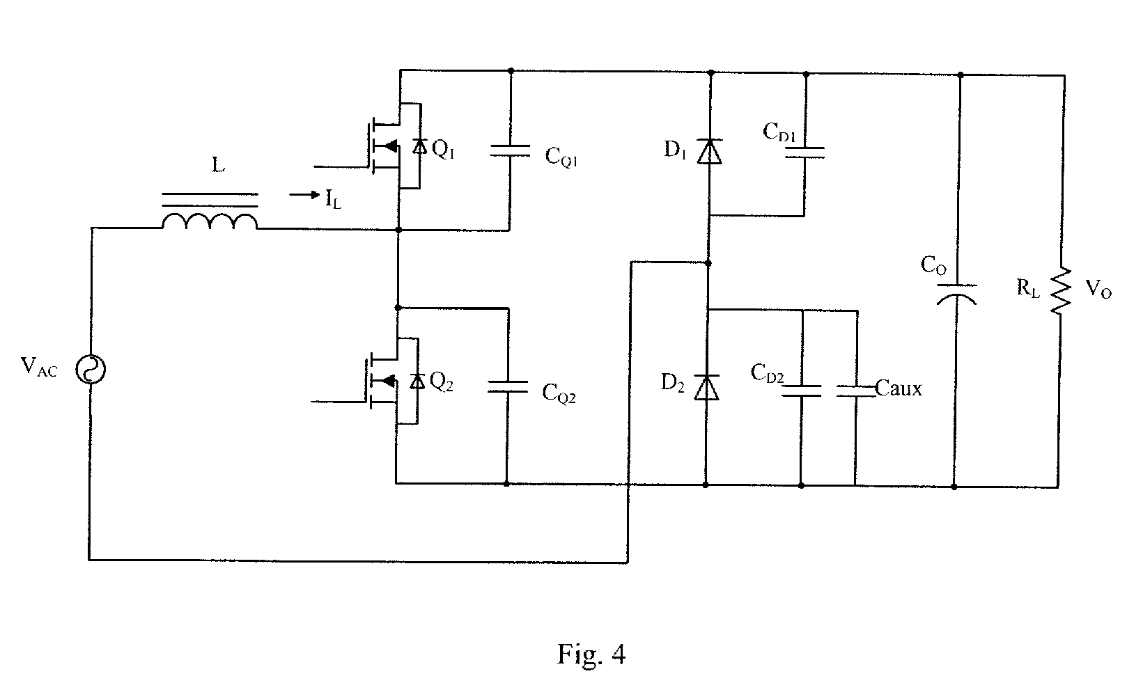
(57) The present disclosure provides a power factor correction circuit. The power factor
correction circuit includes an AC power (Vac), a first bridge arm (Q1, Cq1, Q2, Cq2),
a second bridge arm (D1, Cd1, D2, Cd2) and at least one auxiliary capacitor (Caux).
The AC power has first and second ends. The first bridge arm includes first and second
switches (Q1, Q2) connected in series with each other. A second terminal of the first
switch is connected to a first terminal of the second switch, and is coupled to the
first end of the AC power via a first inductor (L). The second bridge arm is connected
in parallel with the first bridge arm, and includes third and fourth switches (D1,
D2) connected in series with each other. A second terminal of the third switch is
connected to a first terminal of the fourth switch and the second end of the AC power.
The auxiliary capacitor (Caux) is connected to the third or fourth switch (D1, D2)
in parallel.
|
|
